1. Introduction
Microfluidic systems that utilize flow instabilities between immiscible fluids to generate suspended droplets have attracted much recent attentions [
1]. In such systems, the ability to controllably generate and merge droplets is of high importance when performing complex chemical or biological analysis [
2]. Droplet generation is achieved by shearing one fluid phase with another, either at a T junction or by using a flow focusing geometry. However, the process of merging (in effect the reverse of generation) is usually not predictable, due to subtle variations in interfacial tension, surface topography of micro channels, and fluidic properties (such as of droplet size and velocity) [
3]. As noted, droplet merging is essential in many applications including sequential reactions [
4], multiple step manipulation of cells or high-throughput bioassays [
5,
6]. Micro mixers are generally designed with channel geometries that decrease the mixing path and increase the contact surface. Several techniques have been developed to merge droplets; these are either active or passive. Passive mixing devices rely entirely on fluid pumping energy and use special channel designs to restructure the flow in a way that reduces the diffusion length and maximizes the contact surface area. Passive mixers were the first microfluidic device reported, often entail less expense and more convenient fabrication than active micro mixers, and can be easily integrated into more complex Lab on Chip devices. The reduction in mixing time is generally achieved by splitting the fluid stream using serial or parallel lamination [
7,
8], hydrodynamically focusing mixing streams [
9], introducing bubbles of gas (slug), or liquid (droplet) into the flow channel walls [
10,
11], fusion chamber [
12,
13] and pillar structure [
14].
Active micro mixers use external energy input as well as fluid pumping energy to introduce time-dependent perturbations that stir and perturb the fluid for accelerating the mixing process [
15] The type of external force employed by active micro mixers can be further categorized as pressure field-driven [
16], acoustic (ultrasonic)-driven [
17], temperature-induced [
18], electric field [
19,
20], dielectrophoresis, electrocoalescence [
21,
22,
23], or magneto-hydrodynamic [
24]. Generally, active micro mixers have higher mixer efficiency [
25]. However, the requirement to integrate peripheral devices such as the actuators for external power source into integrate peripheral devices such as the actuators for the external power source into the micro device, and the complex and expensive fabrication process, limit the implementation of such devices in practical application. Unfortunately, in active mixing mechanism of such as ultrasonic waves, high temperature gradients can damage biological fluids. Therefore, these active mixers are not a popular choice when applying microfluidics to chemical and biological applications [
13]. Moreover, one of the problems to overcome in the conventional droplet-merging method is the synchronization of two droplets so that they arrive at an exact location, perfectly matched, to improve the device efficiency. In particular, desynchronization problem may hamper device efficiency and lead to the additional sorting components to separate the unmerged droplets [
26]. A method to solve the desynchronization problem was proposed by Link
et al. [
21], who used a platform technology whereby droplets are exactly synchronized by using an electric field, while this method may be limited to the case when the droplets are of the same size and viscosity. To overcome desynchronization problems, it is essential to generate droplets alternately and regularly.
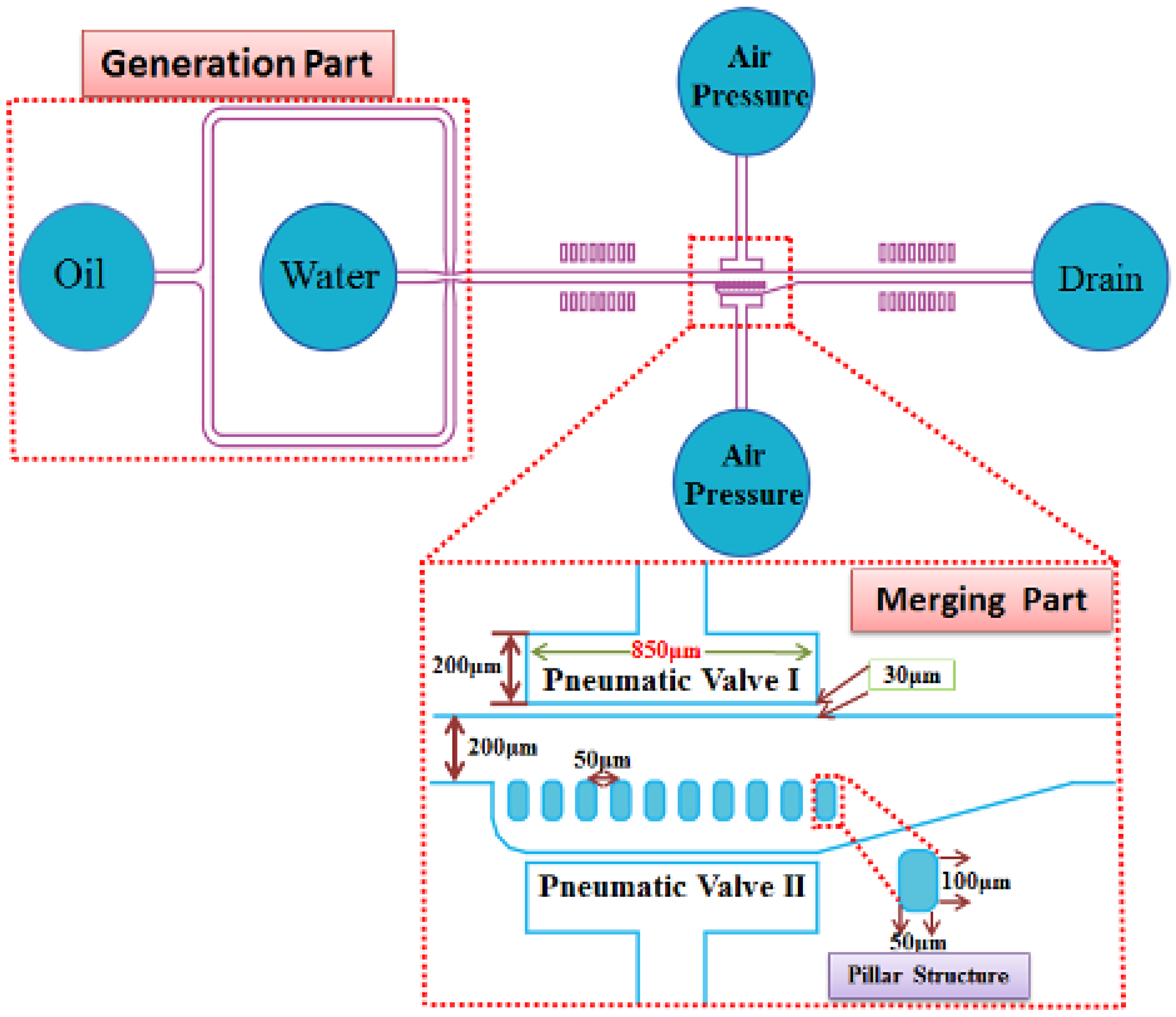
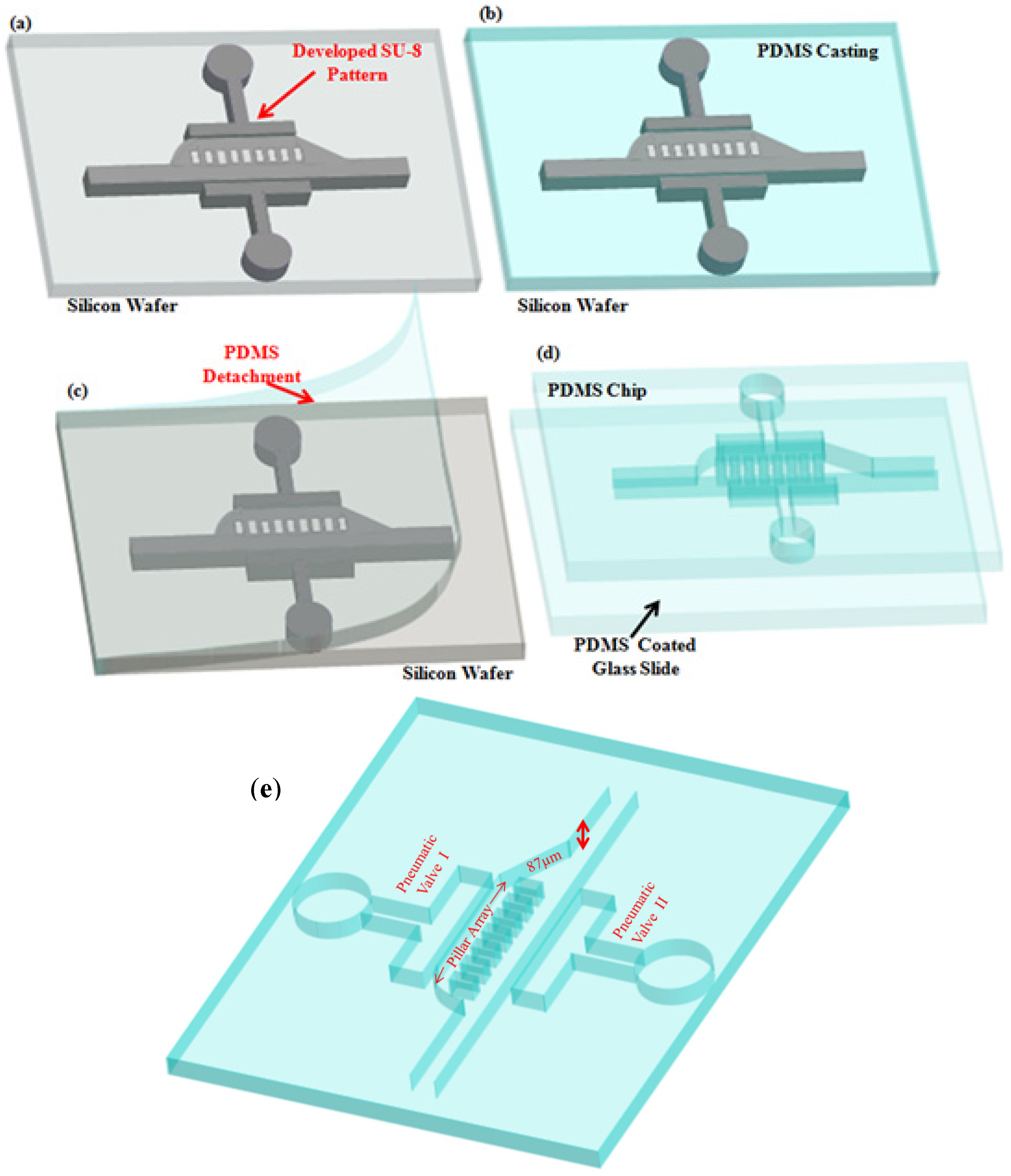
Therefore, we are motivated to develop a simple and efficient active under pressure controllable and selective droplet merging device, which can overcome the desynchronozation, and successfully merge the droplets in different numbers and diameters using the same device without making any changes in the structure of the device. The idea of horizontal pneumatic microvalves is adapted from the droplet sorting system, which can deliver target droplets to five different chambers by pneumatically controlled horizontal PDMS microvalves [
27]. Use of the horizontal pneumatic microvalves makes a system very simple with one PDMS layer rather than using vertical pneumatic microvalves, which always consist of multi-layer PDMS structures. From this point of view, we chose the pneumatic microvalves control systems for merging the micro droplets. While the merging methodology with the modification in pillars structures and removing the one pillar array to make one main and one side channel is adapted from the passive droplets merging device consist of a center channel and two side channels separated by micro pillar arrays [
2]. Our device achieved continuous and reproducible merging of droplets.
2. Working Principle of the Device
A schematic structure of the merging part and the flow resistance of carrier flow in the main (Q
m) and the side (Q
s) channel is shown in
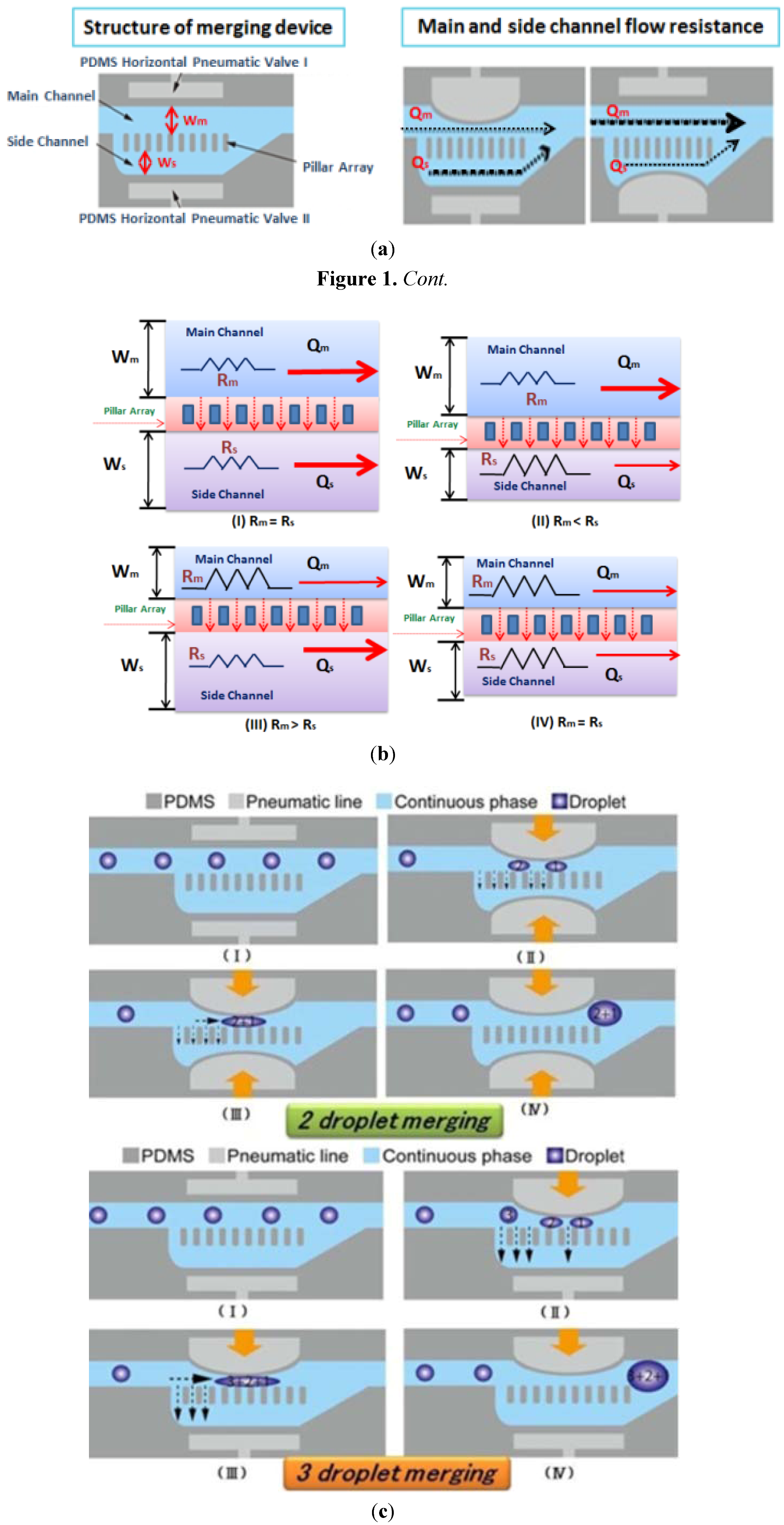
Figure 1a. The merging of the droplets is achieved by varying the flow resistance of the main and the side channel. This flow resistance is controlled through pneumatic valves I and II and a pillar array which provides a bypass path to the flow of the carrier (oil). The pillar array then balance the carrier (oil) in the merging vicinity and traps the droplets in the main channel for merging. There is no direct connection of the pressure on droplets in the merging part.
Figure 1b describes the equivalent band model of the merging part. The working principle of this device can be described in four cases and in all cases the pillar will be the same which means there will be no effect on the pillar array structure instead only the widths of the main and side channel will vary;
Case I: There is no pressure applied through the pneumatic valves, so the widths of the main (Wm) and the side (Ws) channels are equal, in that case the resistance of the main (Rm) and side (Rs) channel is low and the carrier flow (Qm and Qs) is high. So random merging of the droplets will occur. The droplets flow in this case in the main channel as a straight micro channel because they will not face any resistance in their flow path inside the main channel and also no sister droplets will be generated because of the pillar array.
Random merging achieved at
Case II: In this case we apply the pressure through Valve II on the side channel. The width of the side channel decreases with the increase in pressure and the resistance is high than the main channel. The droplets will not merge either, but their flow will be normal as if in a straight channel.
Case III: We applied the pressure on Valve I, through which the resistance of the main channel increased and in comparison the resistance of the side channel is lower than the main channel. With this combination, we achieved the merging of three small droplets as shown in
Figure 1c. In addition, varying the pressure of this valve we can achieve the three large droplets merging with different pressure.
Three droplets merging achieved at
Case IV: When pressure is applied on pneumatic valves, the widths of channels decrease and the resistances will be higher. The flow of carrier will be low as well, so the droplets will face more resistance in their flow path and it will be easy to pin them in different numbers and sizes inside the main channel for merging purposes. With different combinations of pressures on valve I and valve II we will be able to control the gap between the different droplets in small, medium and large sizes in different numbers without any generation of sister droplets in the side channel for merging as shown in
Figure 1c.
Two and three droplets achieved at
To summarize the working principle of active merging device the droplets are continuously injected to the merging part with carrier flow. The Valve I controls flow velocity of the droplets, which are widely changed by the droplet sizes. Therefore, the intermediate carrier flows through the pillars by the pressure balance; the space between the droplets can be controlled by combination of Valve I and Valve II. The controlled number of droplets are trapped and then merged by applying appropriate pressure to Valve I and Valve II.
Figure 1.
Working principal of the merging device (a) Schematics of the structure and the main and side channel flow resistance (b) equivalent band model of the merging device (c) Two and three droplets merging with the different combinations of Valve I and Valve II.
Figure 1.
Working principal of the merging device (a) Schematics of the structure and the main and side channel flow resistance (b) equivalent band model of the merging device (c) Two and three droplets merging with the different combinations of Valve I and Valve II.
5. Results and discussion
Different diameter droplets were generated with the three different water (distilled) and carrier (sunflower oil) flow rates is shown in
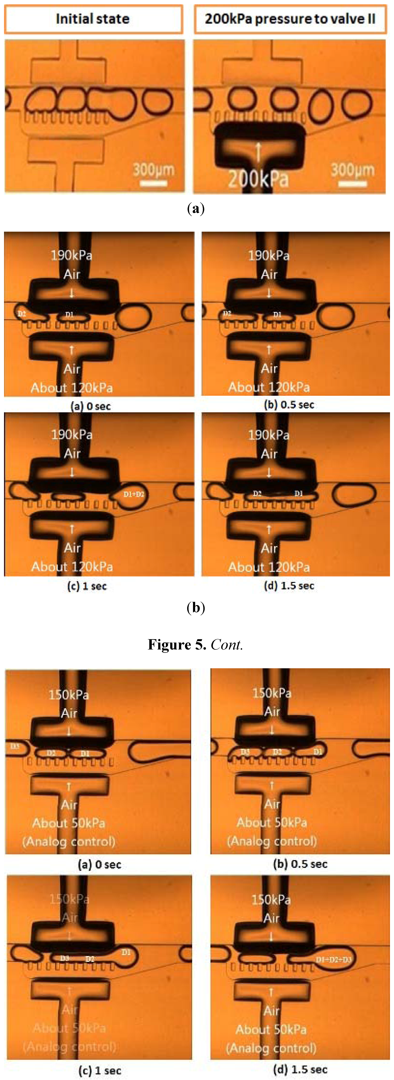
Table 1. We successfully merged small, medium and large droplets in different numbers. Initially we generated a droplet 300 µm in diameter using a co-flowing generation method with a flow rate of 0.5 µL/min of water and carrier (oil) as shown in
Figure 5a. This demonstrates that initially the droplet flow was not stable inside the merging chamber, but after we applied 200 kPa air pressure in Valve II. The flow of droplets came in uniform intervals. Merging of two droplets was achieved under a pressure of 190 kPa (Valve I) and 120 kPa (Valve II) as shown in
Figure 5b and merging of three droplets under pressure of 150 kPa (Valve I) and 50kPa (Valve II) as shown in
Figure 5c.
Table 1.
Different diameter droplets generation with different flow rates of water and oil.
Table 1.
Different diameter droplets generation with different flow rates of water and oil.
| S:No | Oil Flow Rate | Water Flow Rate | Droplet Diameter |
|---|
| 1. | 0.5 µL/min | 0.1 µL/min | 50 µm |
| 2. | 0.5 µL/min | 0.5 µL/min | 100 µm |
| 3. | 0.3 µL/min | 0.8 µL/min | 300 µm |
Figure 5.
Sequence of images demonstrating the droplets merging process under different pneumatic valve Pressures with time sequence (a) initial state of droplets flow in merging chamber before and after applying pressure (b) Captured images of two droplets merging (c) Captured images of three droplets merging.
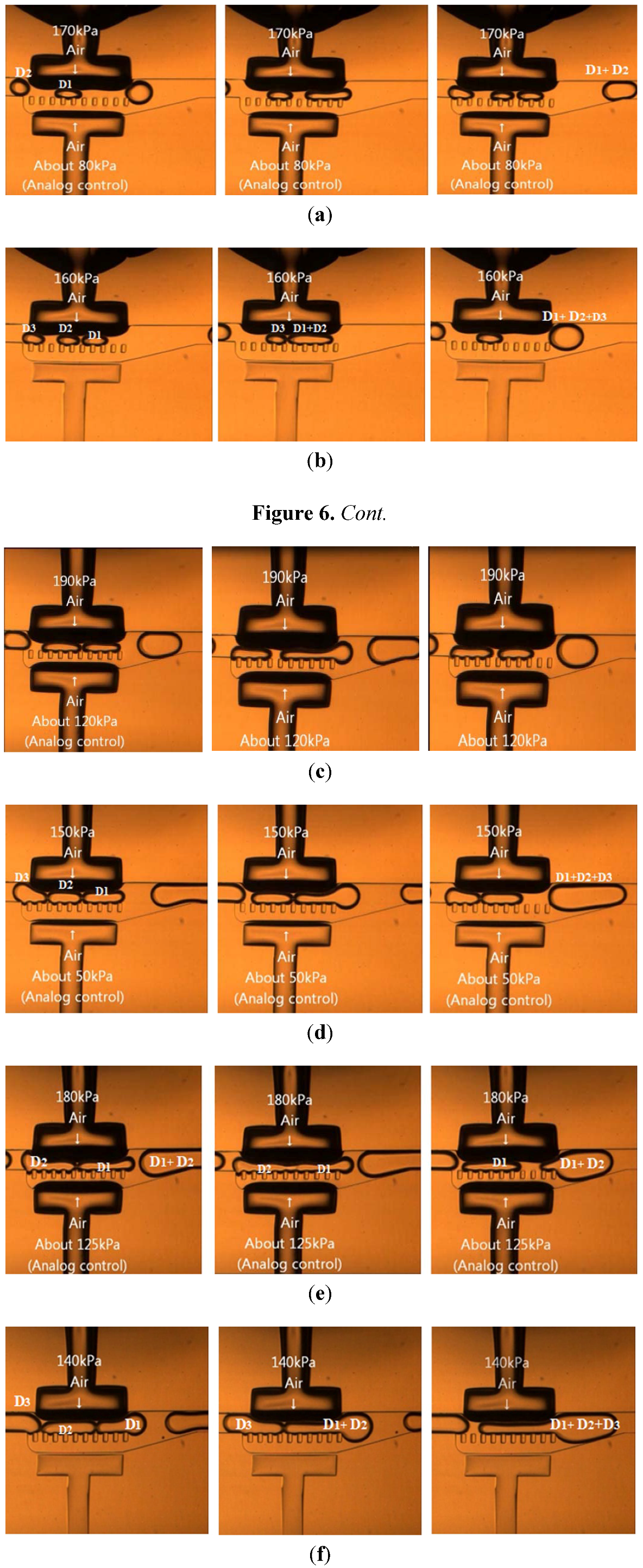
Figure 6 provides a detailed analysis of the merging process of different diameter droplets under different pneumatic valve pressures and
Table 2 displays the different numbers of merged droplets under the 15 s time interval. Small droplets were efficiently generated with flow rates 0.1 µL/min (water) and 0.5 µL/min (oil) as mentioned in
Table 1. The first droplet entered the merging chamber, slowed down to the pause position and waited for the consequent droplet to enter the main channel whose resistance was controlled with pneumatic Valve I. With Valve I pressure at 170 kPa and Valve II pressure at 80 kPa, the merging of two small droplets was attained as the head of the second droplet pressed the tail of the first droplet and initiated the forward flow of the merged droplets towards the drain channel. In the 15 s time interval we successfully merged six pairs of two small droplets is shown in
Figure 6a. Additionally, four sets of three small droplets were merged with a pressure of 160 kPa in Valve I as shown in
Figure 6b.
Medium droplets were produced with flow rates of water 0.5 µL/min and carrier (oil) 0.5 µL/min; fifteen pairs of two droplets were merged with in the designated time duration for all diameter droplets, with the 190 kPa pressure in valve I and 120 kPa pressure in Valve II as shown in
Figure 6c. The three medium droplets merging (nine sets) were also efficiently done with the 150kPa pressure valve I and 50 kPa pressure of valve II as shown in
Figure 6d. Furthermore, it was observed that the efficient mixing of large droplets (generated with the flow rate of water 0.8 µL/min and carrier (oil) 0.3 µL/min) as presented in
Figure 6e was achieved with a 140 kPa pressure in Valve I and 125 kPa in Valve II.
The merging of different droplets in numbers and sizes are effectively realized experimentally, we analyzed with this merging device the efficient and steady emulsion of different droplets can be successfully managed within one second. Hence, from the results it is clear the number of merged droplets for two medium and large droplets were almost three times greater than for smaller droplets merging. Whether in the three droplets merging the number of small droplets emulsion were about half as many as the medium and large droplets mixing.
The merging process was exceptionally stable, and has been operated constantly in multiple experiments of same devices for different time periods. Comparing our results with previous reported work, we succeeded in controllably actively merging different numbers and sizes of droplets under different pressure conditions. The pneumatic valves pressure do not have direct effect on the droplets because they are just used to vary the area of a main and side channel with which the resistance of both channels were changed and we achieved the droplets merging on demand. Furthermore, this device can rapidly merge droplets on demand for different analysis.
Figure 6.
Different sizes and number of droplets merging. (a) Two Small Droplets Merging [(water) = 0.1 μL/min, Carrier (oil) = 0.5 µL/min]; (b) Three Small Droplets Merging [(water) = 0.1 μL/min, Carrier (oil) = 0.5 µL/min]; (c) Two Medium Droplets Merging [(water) = 0.5 μL/min, Carrier (oil) = 0.5 μL/min]; (d) Three Medium Droplets Merging [(water) = 0.5 μL/min, Carrier (oil) = 0.5 μL/min]; (e) Two large Droplets Merging [(water) =0.8 μL/min, Carrier (oil) =0.3 μL/min]; (f) Three Large Droplets Merging [(water) = 0.8 μL/min, Carrier (oil) = 0.3 μL/min].
Table 2.
Two and three (small, medium and large) number of merged droplets with respect to time.
Table 2.
Two and three (small, medium and large) number of merged droplets with respect to time.
| S:No | No of Droplets | Size of Droplets | Pressure | No of Merged Droplets in Time = 15 s |
|---|
| Valve I | Valve II |
|---|
| 1. | Two Droplets Merging | Small | 170 KPa | 80 KPa | 6 |
| Medium | 190 KPa | 120 KPa | 15 |
| Large | 180 KPa | 125 KPa | 14 |
| 2. | Three Droplets Merging | Small | 160 KPa | 0 KPa | 4 |
| Medium | 150 KPa | 50 KPa | 9 |
| Large | 140 KPa | 0 KPa | 11 |
6. Conclusions
The capability for controllable and selective droplet merging using horizontal PDMS pneumatic microvalves and pillar structure has been successfully demonstrated. The numbers and volumes of merged droplets were actively controlled by applying pneumatic pressures. With the variation of pneumatic valves pressures, the flow resistance of the main and side channels varied the flow rate of the carrier and the merging of droplets achieved. With this system, low sample consumption and rapidly mixing samples allow the large exploration of chemical assemblies. We believe that this device will be an effective and attractive choice in biological applications for the screening and synthesis of small molecules without damaging the gradients of samples because the merging is controlled hydrodynamically. Importantly, by using this droplet-merging technique, we can overcome several problems encountered in previous reported work, leading to perfect synchronization, active control, high efficiency, simplicity of device fabrication and prevention of secondary merging. This merging device can be very easily installed in any microfluidic system for rapid and on demand merging purposes.


