

Microfluidics-Engineered Microcapsules: Advances in Thermal Energy Storage and Regulation


Abstract
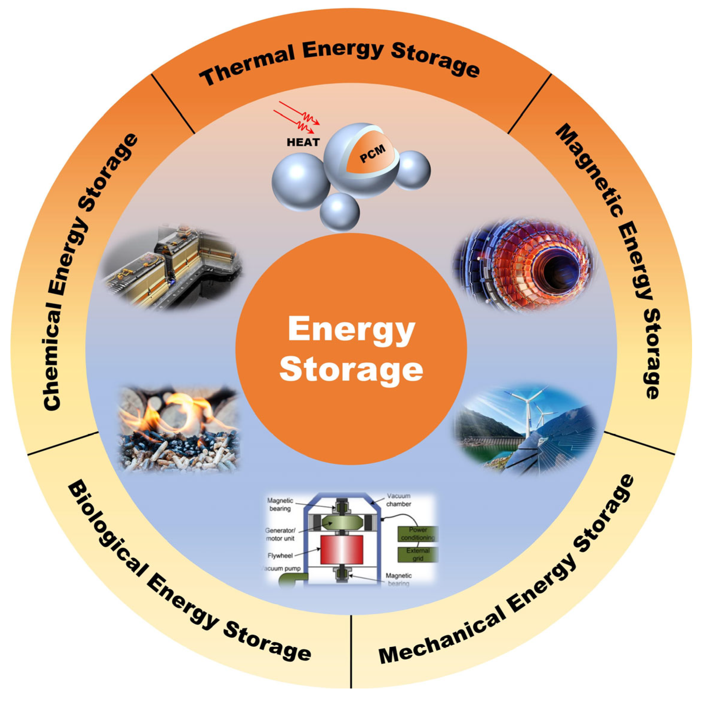
1. Introduction
2. Phase-Change Microcapsules by Droplet Microfluidic
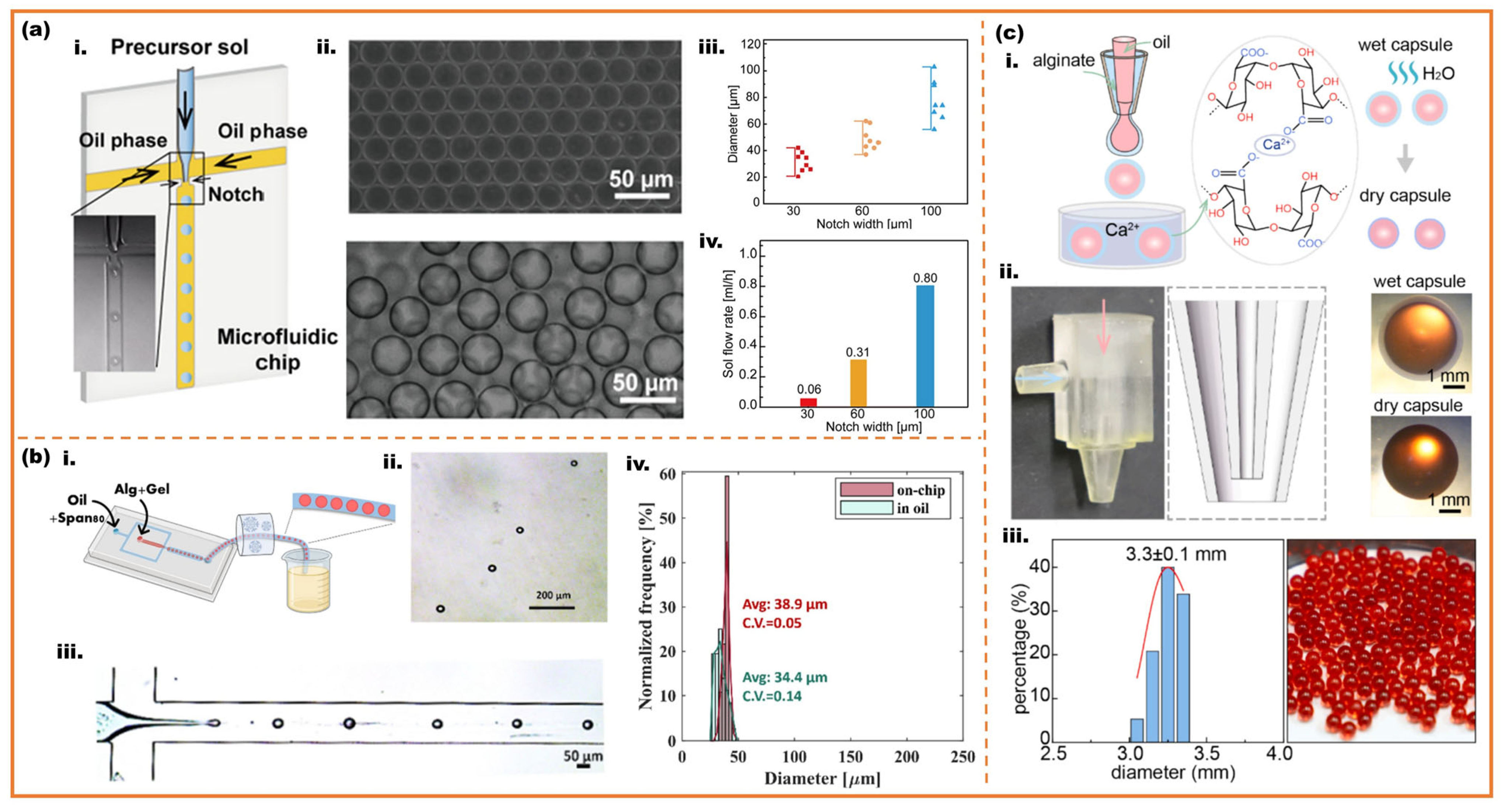
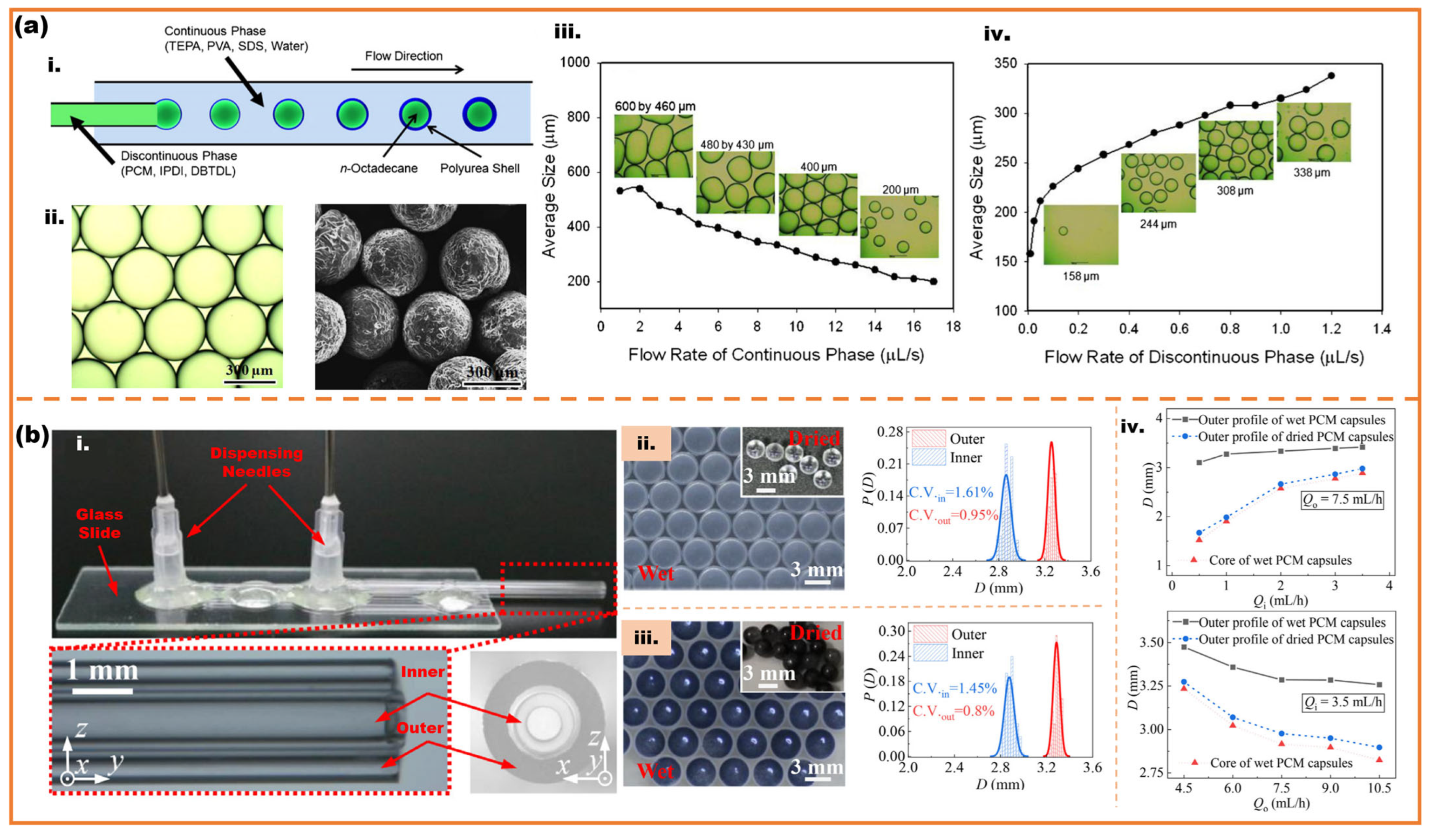
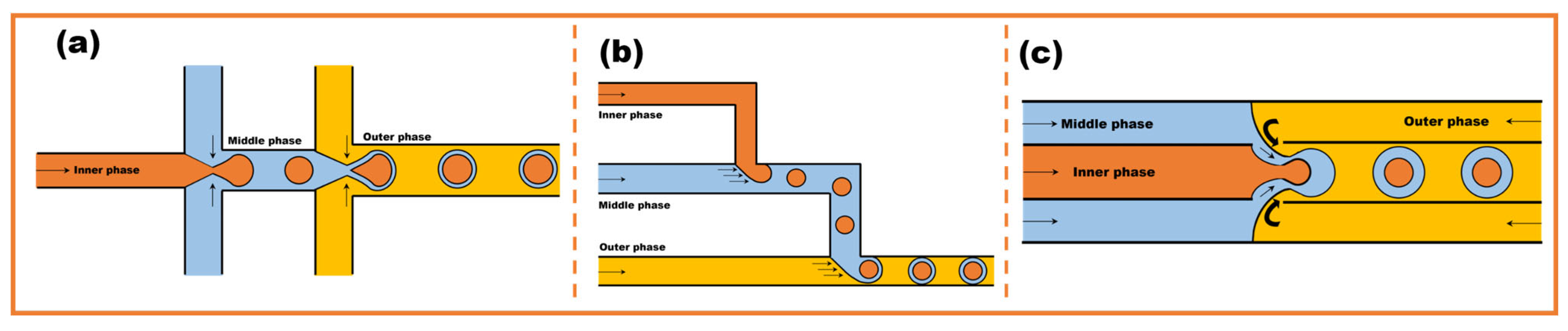
2.1. Monodisperse and Core–Shell Microspheres
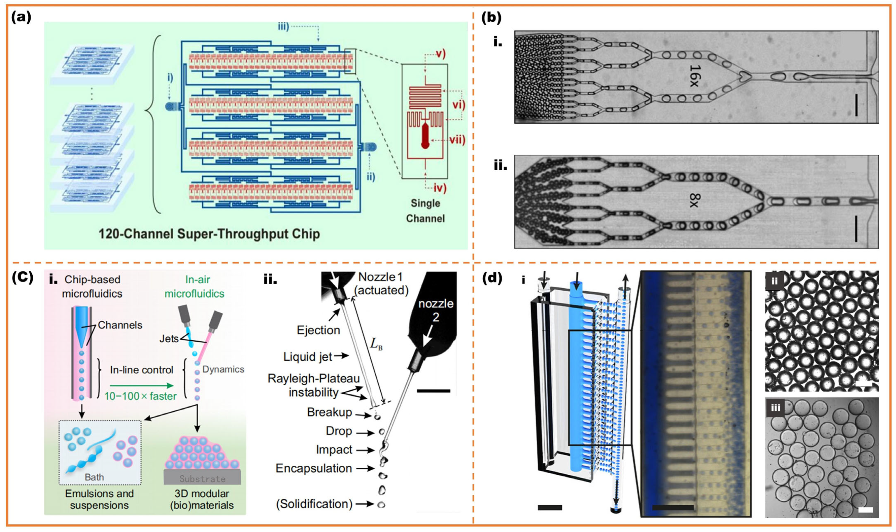
2.2. High-Throughput Microfluidic
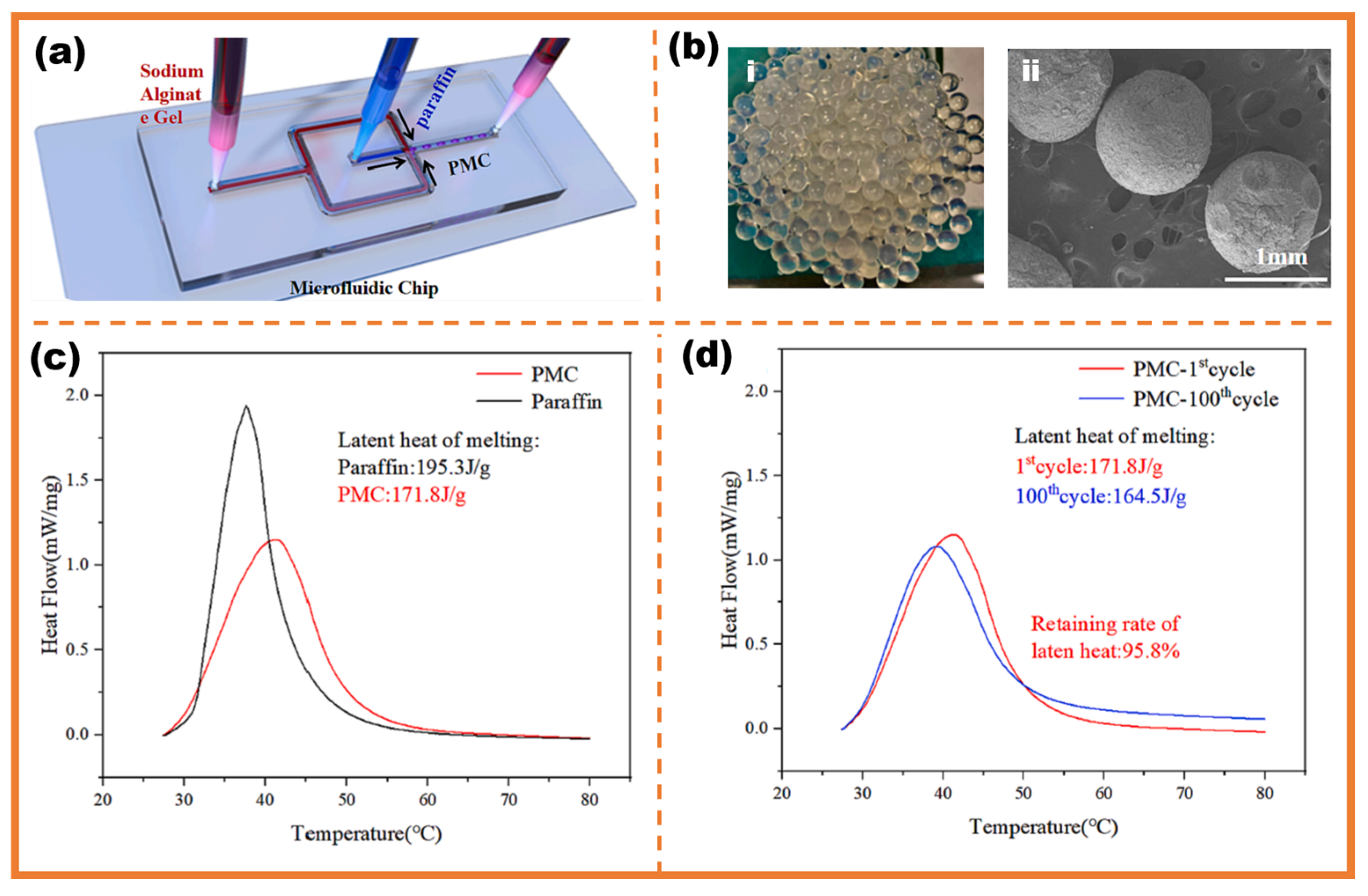
3. Energy Storage Application
4. Thermal Regulation Application
4.1. Biulding
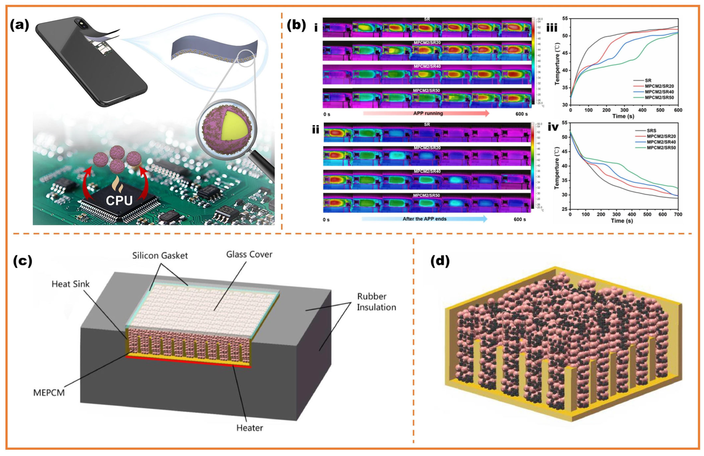
4.2. Electronic Equipment
4.3. Textile
5. Conclusions and Challenge
- (1)
- Material innovation: current PCMs (e.g., n-alkanes) exhibit limited phase-change enthalpy and thermal stability. Future research should prioritize developing novel PCM composites (e.g., eutectic mixtures, metal-enhanced formulations) with higher latent heat, tailored phase transition temperatures, and improved cyclability. These materials have to maintain stability under repeated thermal cycles while minimizing supercooling and phase separation;
- (2)
- Fabrication techniques:
- Sub-micron Particles: Downsizing microcapsules to sub-micron scales (<1 μm) could enhance heat transfer kinetics but complicates production. Current microfluidic methods achieve monodispersity at scales of 10–1000 μm and scaling down may compromise throughput.
- Particle Grading: Monodisperse microcapsules limit packing density in composites (e.g., concrete, slurries). Implementing size-graded distributions (e.g., bimodal/multimodal) during microfluidic fabrication is able to optimize interstitial filling, increasing volumetric enthalpy and thermal conductivity in end-use applications.
- (3)
- High-throughput scalability: While parallelized microfluidics (e.g., kilo-scale flow-focusing arrays, step emulsifiers) boosts droplet production rates to liters per hour, maintaining low size dispersity (CV < 5%) remains challenging at industrial scales. Key bottlenecks include inherent inter-branch flow variations within complex distribution networks, leading to non-uniform shear stress and droplet polydispersity. Furthermore, the extended operation necessary for high throughput exacerbates the risk of chip flow channel clogging, particularly in sensitive or complex emulsion systems (e.g., high viscosity, particle-laden, or multi-phase formulations) where material accumulation at junctions, bends, or low-flow zones becomes problematic. Future designs must integrate intelligent flow distribution networks incorporating real-time pressure and flow sensors with closed-loop active control. This approach dynamically adjusts branch resistances to ensure uniform volumetric flow and shear profile across all parallel units, thereby minimizing droplet size dispersity. Concurrently, robust anti-clogging strategies are essential, which includes: (1) optimizing channel geometry through low-volume, low-tortuosity designs with appropriate surface treatments; (2) integrating localized actuation mechanisms (e.g., piezoelectric pulsations, thermal elements, or integrated bypass flushing ports) at critical nodes to dislodge nascent blockages without interrupting production.
Funding
Conflicts of Interest
Abbreviations
| PCM | Phase-change material |
| TES | Thermal energy storage |
| SHS | Sensible heat storage |
| LHS | Latent heat storage |
| ppm | Parts per million |
| PMMA | Polymethyl-methacrylate |
| PDMS | Polydimethylsiloxane |
| W/O | Water-in-oil |
| O/W | Oil-in-water |
| CV | Coefficient of variation |
| W/O/W | Water-in-oil-in-water |
| O/W/O | Oil-in-water-in-oil |
| UV | Ultraviolet |
| n.a. | Not available |
| DSC | Differential scanning calorimetry |
| SEM | Scanning electron microscopy |
| PCC | Portland cement concrete |
| GPC | Geopolymer concrete |
| wt% | Weight percent |
| CF | Carbon foam |
| EG | Expanded graphite |
| MF | Melamine-formaldehyde |
References
- Bi, C.; Li, G. Analysis of Problems and Countermeasures in the Promotion of New Energy Vehicles in China. Trans. Econ. Bus. Manag. Res. 2024, 9, 143–148. [Google Scholar] [CrossRef]
- Raimi, D.; Newell, R.; Prest, B.; Villanueva, S.; Wingenroth, J. Global Energy Outlook 2024: Peaks or Plateaus; Resources for the Future: Washington, DC, USA, 2024. [Google Scholar]
- Sarbu, I.; Sebarchievici, C. A Comprehensive Review of Thermal Energy Storage. Sustainability 2018, 10, 191. [Google Scholar] [CrossRef]
- Gil, A.; Medrano, M.; Martorell, I.; Lázaro, A.; Dolado, P.; Zalba, B.; Cabeza, L.F. State of the Art on High Temperature Thermal Energy Storage for Power Generation. Part 1—Concepts, Materials and Modellization. Renew. Sustain. Energy Rev. 2010, 14, 31–55. [Google Scholar] [CrossRef]
- Boshell, F.; Vela, I.; Visscher, K. Innovation Outlook: Thermal Energy Storage; International Renewable Energy Agency (IRENA): Abu Dhabi, United Arab Emirates, 2020. [Google Scholar]
- Alva, G.; Lin, Y.; Fang, G. An Overview of Thermal Energy Storage Systems. Energy 2018, 144, 341–378. [Google Scholar] [CrossRef]
- Hasnain, S.M. Review on Sustainable Thermal Energy Storage Technologies, Part I: Heat Storage Materials and Techniques. Energy Convers. Manag. 1998, 39, 1127–1138. [Google Scholar] [CrossRef]
- Li, S.; Li, J.; Feng, Y.; Zhao, Y.; Zhao, Y.; Ding, H.; Gong, S. A Review on Thermal Conductivity of Magnesium and its Alloys. J. Magnes. Alloys 2020, 8, 78–90. [Google Scholar] [CrossRef]
- Zhan, H.; Lin, G.; Li, Y. A Case Study on Energy Conservation Using Building Performance Simulation (BPS) to Validate and Analyse a Phase Change Material (PCM) Integrated Office Building. SSRN Online 2023. [Google Scholar] [CrossRef]
- Alrashdan, A.; Kharrufa, S.; Ahmed, A. Integration of Phase Change Materials in Service Areas of Building Envelopes for Improved Thermal Performance: An Experimental Study in Saudi Arabia. Buildings 2024, 14, 904. [Google Scholar] [CrossRef]
- Franzén, B.; Auer, G.; Lewensohn, R. Minimally Invasive Biopsy-Based Diagnostics in Support of Precision Cancer Medicine. Mol. Oncol. 2024, 18, 2612–2628. [Google Scholar] [CrossRef]
- Yuan, K.; Pan, Y.; Zhang, X.; Zhang, X.; Yin, H.; Chen, W.; Gao, W. Micro/Nano Encapsulated Phase Change Materials: Preparation, Principle, and Emerging Advances in Medical Field. Adv. Funct. Mater. 2024, 34, 2314487. [Google Scholar] [CrossRef]
- Mohamed, H.A.; El-Hadidy, H.; El-Dessouky, H.M. Microencapsulation and its Application in Textile Industry. J. Text. Color. Polym. Sci. 2025, 22.1, 81–87. [Google Scholar] [CrossRef]
- Wang, X.; Jiang, H.; Liang, S.; Yang, C.; Zhang, P. Experimental Study on the Thermal Protection Enhancement of Novel Phase Change Material Integrated Structural Firefighting Gloves Under High-Heat Exposures. Case Stud. Therm. Eng. 2024, 56, 104286. [Google Scholar] [CrossRef]
- Li, M.; Liu, S. Metal-Polyphenol Based Phase Change Microcapsules for Photothermal Conversion and Storage. Sol. Energy Mater. Sol. Cells 2024, 270, 112819. [Google Scholar] [CrossRef]
- Murali, G.; Arjunan, T.V.; Shahapurkar, K.; Tirth, V.; Soudagar, M.E.M.; Khan, T.M.Y.; Elfasakhany, A. Experimental Studies on Solar Reusable Can Air Heating System Integrated with Latent Heat Storage. J. Therm. Anal. Calorim. 2024, 149, 8865–8872. [Google Scholar] [CrossRef]
- Huang, J.; Zhang, Y.; Ding, Y.; Guo, X.; Zhou, H. Advances and Applications of Phase Change Materials (PCMs) and PCMs-Based Technologies. ES Mater. Manuf. 2021, 13, 23–39. [Google Scholar] [CrossRef]
- Su, W.; Darkwa, J.; Kokogiannakis, G. Review of Solid–Liquid Phase Change Materials and their Encapsulation Technologies. Renew. Sustain. Energy Rev. 2015, 48, 373–391. [Google Scholar] [CrossRef]
- Lane, G.A. Solar Heat Storage: Latent Heat Materials, 1st ed.; CRC Press: Boca Raton, FL, USA, 1983; Volume 1. [Google Scholar]
- Sharma, S.D.; Kitano, H.; Sagara, K. Phase Change Materials for Low Temperature Solar Thermal Applications. Res. Rep. Fac. Eng. Mie Univ. 2004, 29, 31–64. [Google Scholar]
- Wu, Y.; Chen, M.; Zhao, G.; Qi, D.; Zhang, X.; Li, Y.; Huang, Y.; Yang, W. Recyclable solid–solid phase change materials with superior latent heat via reversible anhydride-alcohol crosslinking for efficient thermal storage. Adv. Mater. 2024, 36, 2311717. [Google Scholar] [CrossRef]
- Geng, X.; Hu, Y.; Pan, H.; Wang, C.; Liu, Z.; He, X. Biodegradable polylactic acid/polyethylene glycol blends as form-stable phase change materials for thermal energy storage and management. Polymer 2024, 300, 127023. [Google Scholar] [CrossRef]
- Guo, Y.; Zhao, J.; Xu, X.; Zhang, Y.; Gao, X.; Zhang, H.; Wang, H. Phase Change Materials Meet Microfluidic Encapsulation. Adv. Sci. 2023, 11, 2304580. [Google Scholar] [CrossRef]
- Gao, W.; Zhao, L.; Cheng, C.; Liang, S.; Wu, J.; Lin, Z.; Fu, J. Microfluidic Method–Based Encapsulated Phase Change Materials: Fundamentals, Progress, and Prospects. Renew. Sustain. Energy Rev. 2023, 171, 112998. [Google Scholar] [CrossRef]
- Mateovic, T.; Kriznar, B.; Bogataj, M.; Mrhar, A. The Influence of Stirring Rate on Biopharmaceutical Properties of Eudragit RS Microspheres. J. Microencapsul. 2002, 19, 29–36. [Google Scholar] [CrossRef]
- Kadam, N.R.; Suvarna, V. Microsphere: A Brief Review. Asian J. Biomed. Pharm. Sci. 2015, 5, 13–19. [Google Scholar]
- Ho, Y.K.; Choi, Y.H.; Wiley, D.E. Preparation of Alginate Microspheres Using Membrane Emulsification Method. Membr. J. 2004, 14, 218–229. [Google Scholar]
- Guha, K.; Rani, M.U.; Sarma, S. MEMS and Microfluidics in Healthcare. In Microfluidics and Bio-MEMS: Devices and Applications; Springer: Singapore, 2022; pp. 1–30. [Google Scholar]
- Juang, Y.J.; Chiu, Y.J. Fabrication of Polymer Microfluidics: An Overview. Polymers 2022, 14, 2028. [Google Scholar] [CrossRef] [PubMed]
- Manz, A.; Graber, N.; Widmer, H.M. Miniaturized Total Chemical Analysis Systems: A Novel Concept for Chemical Sensing. Sens. Actuators B Chem. 1990, 1, 244–248. [Google Scholar] [CrossRef]
- Riahi, R.; Tamayol, A.; Shaegh, S.A.M.; Ghaemmaghami, A.M.; Dokmeci, M.R.; Khademhosseini, A. Microfluidics for Advanced Drug Delivery Systems. Curr. Opin. Chem. Eng. 2015, 7, 101–112. [Google Scholar] [CrossRef]
- Mu, X.; Zhang, H.; Wang, L.; Gu, W.; Gall, K. Microfluidics for Manipulating Cells. Small 2013, 9, 9–21. [Google Scholar] [CrossRef]
- Huang, L.; Chen, Y.; Feng, Y.; He, Z.; Shen, Y. One-Step Microfluidic Synthesis of Spherical and Bullet-Like Alginate Microcapsules with a Core–Shell Structure. Colloids Surf. A Physicochem. Eng. Asp. 2021, 608, 125612. [Google Scholar] [CrossRef]
- Cramer, C.; Fischer, P.; Windhab, E.J. Drop Formation in a Co-Flowing Ambient Fluid. Chem. Eng. Sci. 2004, 59, 3045–3058. [Google Scholar] [CrossRef]
- Thorsen, T.; Roberts, R.W.; Arnold, F.H.; Quake, S.R. Dynamic Pattern Formation in a Vesicle-Generating Microfluidic Device. Phys. Rev. Lett. 2001, 86, 4163–4166. [Google Scholar] [CrossRef]
- Garstecki, P.; Fuerstman, M.J.; Stone, H.A.; Whitesides, G.M. Formation of Droplets and Bubbles in a Microfluidic T-Junction—Scaling and Mechanism of Break-Up. Lab Chip 2006, 6, 437–446. [Google Scholar] [CrossRef]
- Anna, S.L.; Bontoux, N.; Stone, H.A. Formation of Dispersions Using “Flow Focusing” in Microchannels. Appl. Phys. Lett. 2003, 82, 364–366. [Google Scholar] [CrossRef]
- Dreyfus, R.; Tabeling, P.; Willaime, H. Ordered and Disordered Patterns in Two-Phase Flows in Microchannels. Phys. Rev. Lett. 2003, 90, 144505. [Google Scholar] [CrossRef] [PubMed]
- Haeberle, S.; Zengerle, R. Microfluidic Platforms for Lab-on-a-Chip Applications. Lab Chip 2007, 7, 1094–1110. [Google Scholar] [CrossRef] [PubMed]
- Qin, D.; Xia, Y.; Whitesides, G.M. Soft Lithography for Micro- and Nanoscale Patterning. Nat. Protoc. 2010, 5, 491–502. [Google Scholar] [CrossRef] [PubMed]
- Xu, J.H.; Li, S.W.; Tan, J.; Luo, G.S. Controllable Preparation of Monodisperse O/W and W/O Emulsions in the Same Microfluidic Device. Langmuir 2006, 22, 7943–7946. [Google Scholar] [CrossRef]
- Trujillo-Cayado, L.A.; Ramírez, P.; Alfaro, M.C.; Muñoz, J. A Further Step in the Development of Oil-in-Water Emulsions Formulated with a Mixture of Green Solvents. Ind. Eng. Chem. Res. 2016, 55, 7259–7266. [Google Scholar] [CrossRef]
- Dao, T.D.; Jeong, H.M. Novel Stearic Acid/Graphene Core–Shell Composite Microcapsule as a Phase Change Material Exhibiting High Shape Stability and Performance. Sol. Energy Mater. Sol. Cells 2015, 137, 227–234. [Google Scholar] [CrossRef]
- Dai, Z.; Zhang, X.; Wang, L.; Chen, Y.; Chen, Q. Microfluidic-Assisted Sol–Gel Preparation of Monodisperse Mesoporous Silica Microspheres with Controlled Size, Surface Morphology, Porosity and Stiffness. Nanoscale 2025, 17, 5222–5231. [Google Scholar] [CrossRef]
- Chen, S.; Shahar, T.; Cohen, S. Thermo-Controlled Microfluidic Generation of Monodisperse Alginate Microspheres Based on External Gelation. RSC Adv. 2024, 14, 32021–32028. [Google Scholar] [CrossRef]
- Zheng, Y.; Zhang, Y.; Li, J.; Liu, X.; Liu, Z. High-Throughput Preparation of Monodisperse Biocompatible Core-Shell Capsules by 3D-Printed Microfluidics. Chem. Eng. Sci. 2025, 304, 121104. [Google Scholar] [CrossRef]
- Tahan Latibari, S.; Mehrali, M.; Mehrali, M.; Mahlia, T.M.I.; Metselaar, H.S.C. Fabrication and Performances of Microencapsulated Palmitic Acid with Enhanced Thermal Properties. Energy Fuels 2015, 29, 1010–1018. [Google Scholar] [CrossRef]
- Lone, S.; Chew, S.F.; van der Walle, C.F. Facile and Highly Efficient Microencapsulation of a Phase Change Material Using Tubular Microfluidics. Colloids Surf. A Physicochem. Eng. Asp. 2013, 422, 61–67. [Google Scholar] [CrossRef]
- Hao, G.; Dong, H.; Zhang, Z.; Zhou, J.; Liu, Y.; Chen, Y. Controlled Microfluidic Encapsulation of Phase Change Material for Thermo-Regulation. Int. J. Heat Mass Transf. 2022, 190, 122738. [Google Scholar] [CrossRef]
- Poulsen, C.E.; Christensen, K.; Breil, M.P.; Thybo, P.; Qvortrup, K.; Nielsen, S.S.; Hall, V.; Hansen, S.H.; Jensen, H. A Microfluidic Platform for the Rapid Determination of Distribution Coefficients by Gravity-Assisted Droplet-Based Liquid–Liquid Extraction. Anal. Chem. 2015, 87, 6265–6270. [Google Scholar] [CrossRef]
- Zhang, Y.; Nguyen, N.T. A Perspective on Magnetic Microfluidics: Towards an Intelligent Future. Biomicrofluidics 2022, 16, 011301. [Google Scholar] [CrossRef]
- Vladisavljević, G.T.; Al Nuumani, R.; Nabavi, S.A. Microfluidic Production of Multiple Emulsions. Micromachines 2017, 8, 75. [Google Scholar] [CrossRef]
- Utada, A.S.; Lorenceau, E.; Link, D.R.; Kaplan, P.D.; Stone, H.A.; Weitz, D.A. Monodisperse Double Emulsions Generated From a Microcapillary Device. Science 2005, 308, 537–541. [Google Scholar] [CrossRef]
- Abate, A.R.; Weitz, D.A. High-Order Multiple Emulsions Formed in Poly(dimethylsiloxane) Microfluidics. Small 2009, 5, 2030–2032. [Google Scholar] [CrossRef]
- Nie, Z.; Li, W.; Seo, M.; Xu, S.; Kumacheva, E. Janus and Ternary Particles Generated by Microfluidic Synthesis: Design, Synthesis, and Self-Assembly. J. Am. Chem. Soc. 2006, 128, 9408–9412. [Google Scholar] [CrossRef] [PubMed]
- Wang, W.; Zhang, M.J.; Chu, L.Y. Microfluidic Approach for Encapsulation via Double Emulsions. Curr. Opin. Pharmacol. 2014, 18, 35–41. [Google Scholar] [CrossRef] [PubMed]
- Nurumbetov, G.; Ballard, N.; Bon, S.A.F. A Simple Microfluidic Device for Fabrication of Double Emulsion Droplets and Polymer Microcapsules. Polym. Chem. 2012, 3, 1043–1047. [Google Scholar] [CrossRef]
- Gao, W.; Chen, Y. Microencapsulation of Solid Cores to Prepare Double Emulsion Droplets by Microfluidics. Int. J. Heat Mass Transf. 2019, 135, 158–163. [Google Scholar] [CrossRef]
- Wang, N.; Liu, H.; Wan, J.; Chen, Y. Modelling Double Emulsion Formation in Planar Flow-Focusing Microchannels. J. Fluid Mech. 2020, 895, A22. [Google Scholar] [CrossRef]
- Abate, A.R.; Kutsovsky, M.; Seiffert, S.; Windberg, M.; Rotem, A.; Weitz, D.A. Synthesis of Monodisperse Microparticles from Non-Newtonian Polymer Solutions with Microfluidic Devices. Adv. Mater. 2011, 23, 1757–1760. [Google Scholar] [CrossRef]
- Lee, T.; Liu, L. Lattice Boltzmann Simulations of Micron-Scale Drop Impact on Dry Surfaces. J. Comput. Phys. 2010, 229, 8045–8063. [Google Scholar] [CrossRef]
- Azarmanesh, M.; Farhadi, M.; Azizian, P. Double Emulsion Formation Through Hierarchical Flow-Focusing Microchannel. Phys. Fluids 2016, 28, 032005. [Google Scholar] [CrossRef]
- Lee, T.Y.; Choi, T.M.; Shim, T.S.; Weitz, D.A. Microfluidic Production of Multiple Emulsions and Functional Microcapsules. Lab Chip 2016, 16, 3415–3440. [Google Scholar] [CrossRef]
- Okushima, S.; Nisisako, T.; Torii, T.; Higuchi, T. Controlled Production of Monodisperse Double Emulsions by Two-Step Droplet Breakup in Microfluidic Devices. Langmuir 2004, 20, 9905–9908. [Google Scholar] [CrossRef]
- Chen, Y.; Deng, Z. Hydrodynamics of a Droplet Passing Through a Microfluidic T-Junction. J. Fluid Mech. 2017, 819, 401–434. [Google Scholar] [CrossRef]
- Ngo, I.L.; Khoo, B.C.; Yang, C. A Numerical Study on the Dynamics of Droplet Formation in a Microfluidic Double T-Junction. Biomicrofluidics 2015, 9, 024117. [Google Scholar] [CrossRef] [PubMed]
- Nabavi, S.A.; Vladisavljević, G.T.; Gu, S. Double Emulsion Production in Glass Capillary Microfluidic Device: Parametric Investigation of Droplet Generation Behaviour. Chem. Eng. Sci. 2015, 130, 183–196. [Google Scholar] [CrossRef]
- Akamatsu, K.; Kaneko, Y.; Nakayama, S.; Kikuchi, R.; Yamada, H.; Shibata, T. A Facile Microencapsulation of Phase Change Materials within Silicone-Based Shells by Using Glass Capillary Devices. Colloids Surf. A Physicochem. Eng. Asp. 2019, 567, 297–303. [Google Scholar] [CrossRef]
- Han, X.; Shen, Y.; Guo, X.; Zhang, Y. Microfluidic Encapsulation of Phase-Change Materials for High Thermal Performance. Langmuir 2020, 36, 8165–8173. [Google Scholar] [CrossRef]
- Wang, C.; Gao, W.; Chen, Y.; Fu, J. Fabrication of Microencapsulated Phase Change Materials Using Microfluidics. In Proceedings of the MEMAT 2022; 2nd International Conference on Mechanical Engineering, Intelligent Manufacturing and Automation Technology, Guilin, China, 7–9 January 2022; VDE Verlag: Berlin, Germany, 2022. [Google Scholar]
- Nisisako, T.; Hatsuzawa, T. Microfluidic fabrication of oil-filled polymeric microcapsules with independently controllable size and shell thickness via Janus to core–shell evolution of biphasic droplets. Sens. Actuators B Chem. 2016, 223, 209–216. [Google Scholar] [CrossRef]
- Yao, X.; Zhang, Y.; Du, L.; Liu, J.; Yao, J. Review of the Applications of Microreactors. Renew. Sustain. Energy Rev. 2015, 47, 519–539. [Google Scholar] [CrossRef]
- Gale, B.K.; Jafek, A.R.; Lambert, C.J.; Goenner, B.L.; Moghimifam, H.; Nze, U.C.; Kamande, S.M. A Review of Current Methods in Microfluidic Device Fabrication and Future Commercialization Prospects. Inventions 2018, 3, 60. [Google Scholar] [CrossRef]
- Mulligan, M.K.; Rothstein, J.P. Scale-Up and Control of Droplet Production in Coupled Microfluidic Flow-Focusing Geometries. Microfluid. Nanofluid. 2012, 13, 65–73. [Google Scholar] [CrossRef]
- Liu, X.; Xu, J.; Wu, J.; Guo, Y. High-Throughput Microfluidic Production of Carbon Capture Microcapsules: Fundamentals, Applications, and Perspectives. Int. J. Extreme Manuf. 2024, 6, 032010. [Google Scholar] [CrossRef]
- Su, Y.Y.; Tan, B.T.; Chen, C.H. Simple and Flexible Production of Controllable Emulsion Droplets from Open-Type Co-Flow Microfluidics. Chem. Eng. Sci. 2024, 293, 120027. [Google Scholar] [CrossRef]
- Chen, X.; Li, T.; Zeng, H.; Hu, Z.; Fu, X. Model of Droplet Generation in Flow Focusing Generators Operating in the Squeezing Regime. Microfluid. Nanofluid. 2015, 18, 1341–1353. [Google Scholar] [CrossRef]
- Gupta, A.; Murshed, S.M.S.; Kumar, R. Droplet Formation and Stability of Flows in a Microfluidic T-Junction. Appl. Phys. Lett. 2009, 94, 164107. [Google Scholar] [CrossRef]
- Eggersdorfer, M.L.; Seybold, H.; Ofner, A.; Weitz, D.A.; Studart, A.R. Wetting Controls of Droplet Formation in Step Emulsification. Proc. Natl. Acad. Sci. USA 2018, 115, 9479–9484. [Google Scholar] [CrossRef] [PubMed]
- Han, T.; Wei, J.; Li, Z.; Gao, Z.; Xu, Y.; Zhang, W. Factory-on-Chip: Modularised Microfluidic Reactors for Continuous Mass Production of Functional Materials. Chem. Eng. J. 2017, 326, 765–773. [Google Scholar] [CrossRef]
- Conchouso, D.; Carreno, A.A.A.; Castro, D.; Khan, S.A.; Foulds, I.G. Three-Dimensional Parallelization of Microfluidic Droplet Generators for a Litre per Hour Volume Production of Single Emulsions. Lab Chip 2014, 14, 3011–3020. [Google Scholar] [CrossRef]
- Huang, Y.; Zhang, Y.; Sun, H.; Li, J.; Zhang, X.; Zhu, P. Design Criteria and Applications of Multi-Channel Parallel Microfluidic Module. J. Micromech. Microeng. 2018, 28, 105021. [Google Scholar] [CrossRef]
- Hashimoto, M.; Shevkoplyas, S.S.; Zason, B.; Szymborski, T.; Garstecki, P.; Whitesides, G.M. Formation of Bubbles and Droplets in Parallel, Coupled Flow-Focusing Geometries. Small 2008, 4, 1795–1805. [Google Scholar] [CrossRef]
- Wu, J.; Kong, T.; Yeung, K.W.K.; Shum, H.C.; Lam, R.H.W. Scaling Up the Throughput of Microfluidic Droplet-Based Materials Synthesis: A Review of Recent Progress and Outlook. Appl. Phys. Rev. 2021, 8, 031303. [Google Scholar] [CrossRef]
- Romanowsky, M.B.; Abate, A.R.; Rotem, A.; Holtze, C.; Weitz, D.A. High Throughput Production of Single Core Double Emulsions in a Parallelized Microfluidic Device. Lab Chip 2012, 12, 802–807. [Google Scholar] [CrossRef]
- Yi, H.; Wang, F.; Li, Y.; Zhang, H.; Qin, S.; Li, S.; Hu, Z. Parallelized Microfluidic Droplet Generators with Improved Ladder–Tree Distributors for Production of Monodisperse γ-Al2O3 Microspheres. Particuology 2022, 62, 47–54. [Google Scholar] [CrossRef]
- Håti, A.G.; Morch, Y.A.; Røe, R.; Dyrstad, K.; Sæther, B.; Angell-Petersen, E.; Furuseth, K.; Skotland, T.; Sandvig, K.; Sioud, M. Production of Monodisperse Drops from Viscous Fluids. Lab Chip 2018, 18, 648. [Google Scholar] [CrossRef]
- Vladisavljević, G.T.; Kobayashi, I.; Nakajima, M.; Williams, R.A.; Shono, A.; Satoh, K. Long-Term Stability of Droplet Production by Microchannel (Step) Emulsification in Microfluidic Silicon Chips with Large Number of Terraced Microchannels. Chem. Eng. J. 2018, 333, 380–391. [Google Scholar] [CrossRef]
- Li, W.; Greener, J.; Voicu, D.; Kumacheva, E. Multiple Modular Microfluidic (M-3) Reactors for the Synthesis of Polymer Particles. Lab Chip 2009, 9, 2715–2721. [Google Scholar] [CrossRef] [PubMed]
- Tetradis-Meris, G.; Rossetti, D.; de Torres, C.P.; Cao, R.; Ianoul, P.; Lian, G.; Janvier, P. Novel Parallel Integration of Microfluidic Device Network for Emulsion Formation. Ind. Eng. Chem. Res. 2009, 48, 8881–8889. [Google Scholar] [CrossRef]
- Jeong, H.H.; Yelleswarapu, V.R.; Yadavali, S.; Issadore, D.; Lee, D. Kilo-Scale Droplet Generation in Three-Dimensional Monolithic Elastomer Device (3D MED). Lab Chip 2015, 15, 4387–4392. [Google Scholar] [CrossRef] [PubMed]
- Nisisako, T.; Torii, T. Microfluidic Large-Scale Integration on a Chip for Mass Production of Monodisperse Droplets and Particles. Lab Chip 2008, 8, 287–293. [Google Scholar] [CrossRef]
- Amstad, E.; Chen, D.; Zhao, M.X.; Kim, S.H.; Weitz, D.A. Robust Scalable High Throughput Production of Monodisperse Drops. Lab Chip 2016, 16, 4163–4172. [Google Scholar] [CrossRef]
- Stolovicki, E.; Ziblat, R.; Weitz, D.A. Throughput Enhancement of Parallel Step Emulsifier Devices by Shear-Free and Efficient Nozzle Clearance. Lab Chip 2018, 18, 132–138. [Google Scholar] [CrossRef]
- Sun, K.; Zhang, X.; Liu, J.; Liu, Z.; Tan, T.T.Y.; Sun, B. Microfluidic Precision Manufacture of High Performance Liquid Chromatographic Microspheres. Angew. Chem. Int. Ed. 2024, 64, e202418642. [Google Scholar] [CrossRef]
- Hoang, D.A.; Portela, L.M.; Kleijn, C.R.; Kreutzer, M.T.; Van Steijn, V. Design and Characterization of Bubble-Splitting Distributor for Scaled-Out Multiphase Microreactors. Chem. Eng. J. 2014, 236, 545–554. [Google Scholar] [CrossRef]
- Kim, C.M.; Kim, G.M. Fabrication of 512-Channel Geometrical Passive Breakup Device for High-Throughput Microdroplet Production. Micromachines 2019, 10, 709. [Google Scholar] [CrossRef]
- Chen, Y.; Li, G.; Borowsky, L.; Koolivand, A.; Lian, Q. Three-Dimensional Splitting Microfluidics. Lab Chip 2016, 16, 1332. [Google Scholar] [CrossRef] [PubMed]
- Abate, A.R.; Weitz, D.A. Faster Multiple Emulsification with Drop Splitting. Lab Chip 2011, 11, 1911–1915. [Google Scholar] [CrossRef] [PubMed]
- Visser, C.W.; Kamperman, T.; Karbaat, L.P.; Lohse, D.; Karperien, M. In-Air Microfluidics Enables Rapid Fabrication of Emulsions, Suspensions, and 3D Modular (bio)materials. Sci. Adv. 2018, 4, eaao1175. [Google Scholar] [CrossRef] [PubMed]
- Femmer, T.; Kuehne, A.J.C.; Wessling, M. High-Throughput Generation of Emulsions and Microgels in Parallelized Microfluidic Drop-Makers Prepared by Rapid Prototyping. ACS Appl. Mater. Interfaces 2015, 7, 12635–12638. [Google Scholar] [CrossRef]
- Sharma, A.; Tyagi, V.V.; Chen, C.R.; Buddhi, D. Review on Thermal Energy Storage with Phase Change Materials and Applications. Renew. Sustain. Energy Rev. 2009, 13, 318–345. [Google Scholar] [CrossRef]
- Hu, H.; Zhang, H.; Hong, S. Form-Stable Microencapsulated Phase Change Materials for Efficient Solar Thermal Energy Storage. Mater. Lett. 2023, 352, 135166. [Google Scholar] [CrossRef]
- Huang, H.; Wei, Y.; Wang, Y.; Zhao, P.; Li, X. Phase-Changing Microcapsules Incorporated with Black Phosphorus for Efficient Solar Energy Storage. Adv. Sci. 2020, 7, 2000602. [Google Scholar] [CrossRef]
- Sun, J.; Ding, H.; Chen, J.; Cao, L.; Yang, L. Biodegradable Wood Plastic Composites with Phase Change Microcapsules of Honeycomb-BN-Layer for Photothermal Energy Conversion and Storage. Chem. Eng. J. 2022, 448, 137218. [Google Scholar] [CrossRef]
- Liu, H.; Tao, X.; Wu, S.; Ye, Q. MXene-Decorated Magnetic Phase-Change Microcapsules for Solar-Driven Continuous Seawater Desalination with Easy Salt Accumulation Elimination. Chem. Eng. J. 2023, 458, 141395. [Google Scholar] [CrossRef]
- Su, W.; Darkwa, J.; Kokogiannakis, G. Development of Microencapsulated Phase Change Material for Solar Thermal Energy Storage. Appl. Therm. Eng. 2017, 112, 1205–1212. [Google Scholar] [CrossRef]
- Tan, C.; He, Y.; Luo, B.; Liu, M. Microencapsulated Phase Change Material with Chitin Nanocrystals Stabilized Pickering Emulsion for Thermal Energy Storage. Int. J. Biol. Macromol. 2023, 240, 124374. [Google Scholar] [CrossRef] [PubMed]
- Ma, T.; Yang, H.; Lu, L. Using Phase Change Materials in Photovoltaic Systems for Thermal Regulation and Electrical Efficiency Improvement: A Review and Outlook. Renew. Sustain. Energy Rev. 2015, 43, 1273–1284. [Google Scholar] [CrossRef]
- Chandrasekar, M.; Rajkumar, S.; Valavan, D. A Review on the Thermal Regulation Techniques for Non Integrated Flat PV Modules Mounted on Building Top. Energy Build. 2015, 86, 692–697. [Google Scholar] [CrossRef]
- Rathore, P.K.S.; Shukla, S.K.; Gupta, N.K. Potential of Microencapsulated PCM for Energy Savings in Buildings: A Critical Review. Sustain. Cities Soc. 2020, 53, 101884. [Google Scholar] [CrossRef]
- Anisur, M.R.; Mahfuz, M.H.; Kibria, M.A.; Saidur, R.; Metselaar, I.H.S.C.; Mahlia, T.M.I. Curbing Global Warming with Phase Change Materials for Energy Storage. Renew. Sustain. Energy Rev. 2013, 18, 23–30. [Google Scholar] [CrossRef]
- Konuklu, Y.; Ostry, M.; Paksoy, H.O.; Charvat, P. Review on Using Microencapsulated Phase Change Materials (PCM) in Building Applications. Energy Build. 2015, 106, 134–155. [Google Scholar] [CrossRef]
- Hekimoğlu, G.; Sarı, A.; Kaygusuz, K.; Tyagi, V.V.; Sharma, R.K.; Gencel, O. Thermal Management Performance and Mechanical Properties of a Novel Cementitious Composite Containing Fly Acid/Lauric Acid-Myristic Acid as Form-Stable Phase Change Material. Constr. Build. Mater. 2021, 274, 122105. [Google Scholar] [CrossRef]
- Sarı, A.; Hekimoğlu, G.; Kaygusuz, K.; Gencel, O.; Usta, H.; Sharma, R.K. Evaluation of Pumice for Development of Low-Cost and Energy-Efficient Composite Phase Change Materials and Lab-Scale Thermoregulation Performances of Its Cementitious Plasters. Energy 2020, 207, 118242. [Google Scholar] [CrossRef]
- Hekimoğlu, G.; Sarı, A.; Gencel, O.; Tyagi, V.V. Silica Fume/Capric Acid-Stearic Acid PCM Included-Cementitious Composite for Thermal Controlling of Buildings: Thermal Energy Storage and Mechanical Properties. Energy 2021, 219, 119588. [Google Scholar] [CrossRef]
- Cao, V.D.; Pilehvar, S.; Salas-Bringas, C.; Szczotok, A.M.; Rodriguez, J.F.; Carmona, M.; Al-Manasir, N.; Kjøniksen, A.L. Microencapsulated Phase Change Materials for Enhancing the Thermal Performance of Portland Cement Concrete and Geopolymer Concrete for Passive Building Applications. Energy Convers. Manag. 2017, 133, 56–66. [Google Scholar] [CrossRef]
- Dutkowski, K.; Kruzel, M. Experimental Investigation of the Apparent Thermal Conductivity of Microencapsulated Phase-Change-Material Slurry at the Phase-Transition Temperature. Materials 2021, 14, 4124. [Google Scholar] [CrossRef] [PubMed]
- Lemmon, E.W.; Huber, M.L.; McLinden, M.O. Thermophysical Properties of Fluid Systems. In NIST Chemistry WebBook; NIST Standard Reference Database Number 69; National Institute of Standards and Technology: Gaithersburg, MD, USA, 2010. [Google Scholar]
- Zhang, Y.; Liu, C.; Qian, F.; Li, T.; Gao, S.; Wang, Z.; Kong, X. Microencapsulated Phase Change Materials Composited Al2O3–SiO2 Aerogel and the Thermal Regulation Properties. J. Sol-Gel Sci. Technol. 2020, 96, 627–635. [Google Scholar] [CrossRef]
- Long, H.; Liu, F.; Chen, Z.; Li, Y.; Ye, S.; Qin, Y.; Zhao, J. Superhydrophobic Daytime Radiative Cooling Coating Incorporated with Phase Change Microcapsules for Building Thermal Regulation. J. Mater. Sci. 2024, 59, 6459–6475. [Google Scholar] [CrossRef]
- Ali, H.M.; Arshad, A.; Janjua, M.M.; Sajjad, U.; Yan, W.M. Thermal Management of Electronics: An Experimental Analysis of Triangular, Rectangular and Circular Pin-Fin Heat Sinks for Various PCMs. Int. J. Heat Mass Transf. 2018, 123, 272–284. [Google Scholar] [CrossRef]
- Rostamian, F.; Etesami, N.; Mehrali, M. Microencapsulation of Eutectic Phase Change Materials for Temperature Management of the Satellite Electronic Board. Appl. Therm. Eng. 2024, 236, 121592. [Google Scholar] [CrossRef]
- Jiang, F.; Qiu, G.; Wang, X. Energy Harvesting and Thermal Management System in Aerospace. Front. Mater. 2022, 9, 907858. [Google Scholar] [CrossRef]
- Alshaer, W.G.; Nada, S.A.; Rady, M.A.; Baracu, A.; Ducu, C.; Minea, A.A. Thermal Management of Electronic Devices Using Carbon Foam and PCM/Nanocomposite. Int. J. Therm. Sci. 2015, 89, 79–86. [Google Scholar] [CrossRef]
- Zhu, X.; Zhang, J.; Zhu, W.; Yuan, T.; Fan, X. Stable Microencapsulated Phase Change Materials with Ultrahigh Payload for Efficient Cooling of Mobile Electronic Devices. Energy Convers. Manag. 2020, 223, 113478. [Google Scholar] [CrossRef]
- Ren, Q.; Guo, P.; Zhu, J. Thermal Management of Electronic Devices Using Pin-Fin Based Cascade Microencapsulated PCM/Expanded Graphite Composite. Int. J. Heat Mass Transf. 2020, 149, 119199. [Google Scholar] [CrossRef]
- Pause, B. Textiles with Improved Thermal Capabilities through the Application of Phase Change Material (PCM) Microcapsules. Mell. Textilber. Int. Text. Rep. 2000, 81, E149. [Google Scholar]
- Hossain, M.T.; Khan, T.M.Y.; Chowdhury, M.S.H.; Sharmin, N.; Alam, M.S. Fabrications, Classifications, and Environmental Impact of PCM-Incorporated Textiles: Current State and Future Outlook. ACS Omega 2023, 8, 45164–45176. [Google Scholar] [CrossRef]
- Salaün, F.; Devaux, E.; Bourbigot, S.; Rumeau, P. Thermoregulating Response of Cotton Fabric Containing Microencapsulated Phase Change Materials. Thermochim. Acta 2010, 506, 82–93. [Google Scholar] [CrossRef]
- Shin, Y.; Yoo, D.I.; Son, K. Development of Thermoregulating Textile Materials with Microencapsulated Phase Change Materials (PCM). II. Preparation and Application of PCM Microcapsules. J. Appl. Polym. Sci. 2005, 96, 2005–2010. [Google Scholar] [CrossRef]
- Zhang, W.; Yi, Z.; Wang, S. Preparation of PMMA/SiO2 PCM Microcapsules and its Thermal Regulation Performance on Denim Fabric. Pigment Resin Technol. 2020, 49, 491–499. [Google Scholar] [CrossRef]
- Gu, B.; Li, G.; Zhang, Q.; Pan, H.; Duan, M.; Weng, L.; Zhao, D. A novel method for increasing phase-change microcapsules in nanofiber textile through electrospinning. Adv. Funct. Mater. 2025, 35, 2412089. [Google Scholar] [CrossRef]
- Xiao, Q.; Yuan, W.; Xu, J.; Li, J.; Gan, G. Thermal Conductivity Enhancement of Hydrated Salt Phase Change Materials Employing Copper Foam as the Supporting Material. Sol. Energy Mater. Sol. Cells 2019, 199, 91–98. [Google Scholar] [CrossRef]
- Wang, F.; Yu, J.; Wang, J.; Xu, S.; Wu, M. Progress in Application of Phase-Change Materials to Cooling Clothing. J. Energy Storage 2023, 60, 106614. [Google Scholar] [CrossRef]


| Material | Temperature (°C) | Thermal Conductivity (W/(mK)) | Phase-Change Enthalpy (kJ/kg) |
|---|---|---|---|
| Molten salts (NaNO3-KNO3-NaNO2) | 142 | 0.60 | 75–84 |
| Natural Ester Oil | −25 | 0.16–0.23 | 150–220 |
| n-Dodecane (C12H26) | −12 | 0.21 (s), 0.21 (l) | 216 |
| n-Pentadecane (C15H32) | 10 | 0.17 | 207 |
| n-Hexadecane (C16H34) | 18.2 | 0.21 (s) | 238 |
| n-Octadecane (C18H38) | 28.2 | 0.35 (s), 0.149 (l) | 245 |
| n-Nonadecane (C19H40) | 31.9 | 0.21 (s) | 222 |
Disclaimer/Publisher’s Note: The statements, opinions and data contained in all publications are solely those of the individual author(s) and contributor(s) and not of MDPI and/or the editor(s). MDPI and/or the editor(s) disclaim responsibility for any injury to people or property resulting from any ideas, methods, instructions or products referred to in the content. |
© 2025 by the authors. Licensee MDPI, Basel, Switzerland. This article is an open access article distributed under the terms and conditions of the Creative Commons Attribution (CC BY) license (https://creativecommons.org/licenses/by/4.0/).
Share and Cite
Li, Y.; Zhang, J.; Zhuo, L.; Wang, X.; Sun, J.; Xue, P.; Chen, K. Microfluidics-Engineered Microcapsules: Advances in Thermal Energy Storage and Regulation. Micromachines 2025, 16, 830. https://doi.org/10.3390/mi16070830
Li Y, Zhang J, Zhuo L, Wang X, Sun J, Xue P, Chen K. Microfluidics-Engineered Microcapsules: Advances in Thermal Energy Storage and Regulation. Micromachines. 2025; 16(7):830. https://doi.org/10.3390/mi16070830
Chicago/Turabian StyleLi, Yuhan, Jian Zhang, Lin Zhuo, Xianjing Wang, Jingyao Sun, Ping Xue, and Ke Chen. 2025. "Microfluidics-Engineered Microcapsules: Advances in Thermal Energy Storage and Regulation" Micromachines 16, no. 7: 830. https://doi.org/10.3390/mi16070830
APA StyleLi, Y., Zhang, J., Zhuo, L., Wang, X., Sun, J., Xue, P., & Chen, K. (2025). Microfluidics-Engineered Microcapsules: Advances in Thermal Energy Storage and Regulation. Micromachines, 16(7), 830. https://doi.org/10.3390/mi16070830