
Research on Tbps and Kilometer-Range Transmission of Terahertz Signals

Abstract
1. Introduction
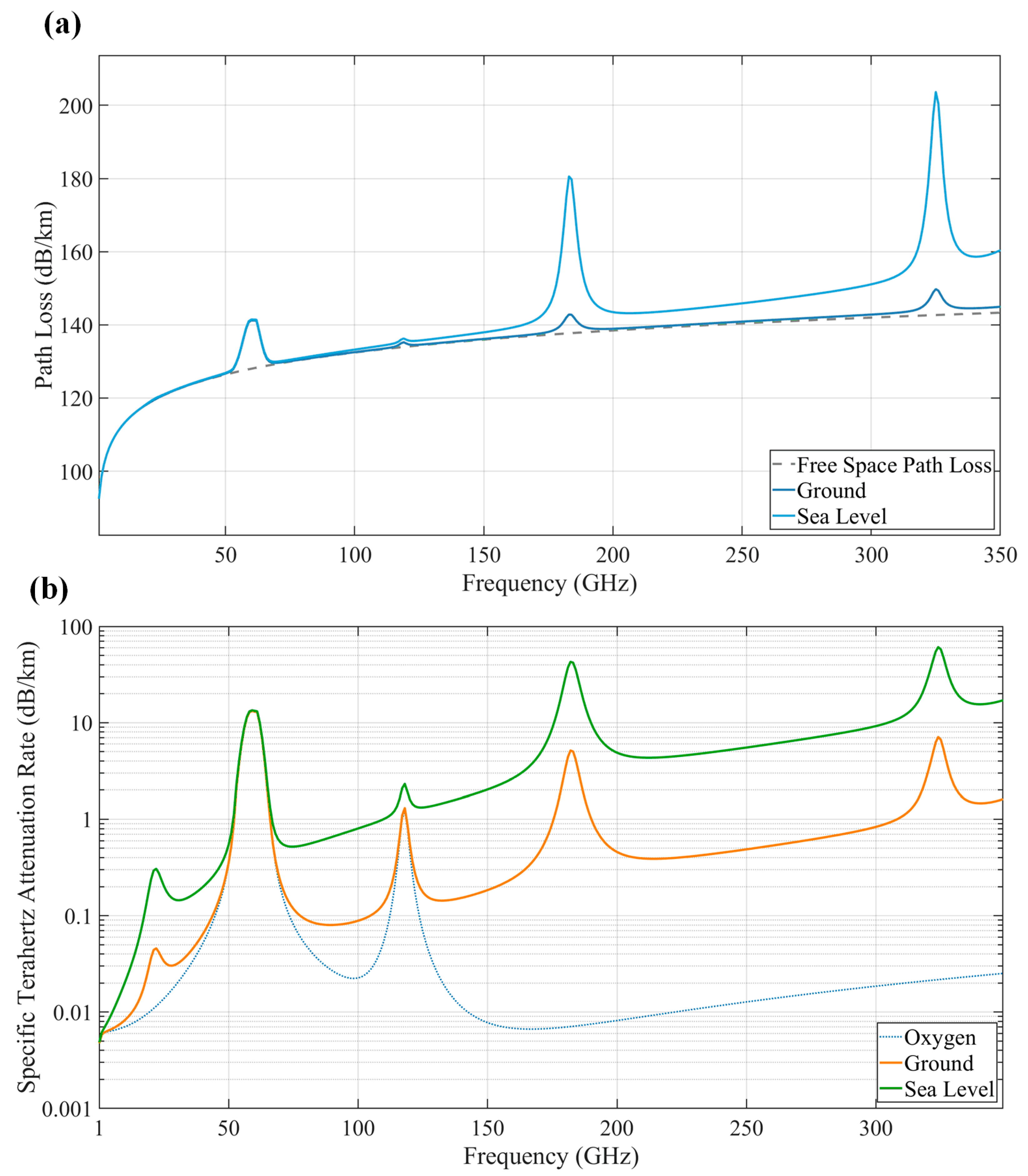
2. Terahertz Signal
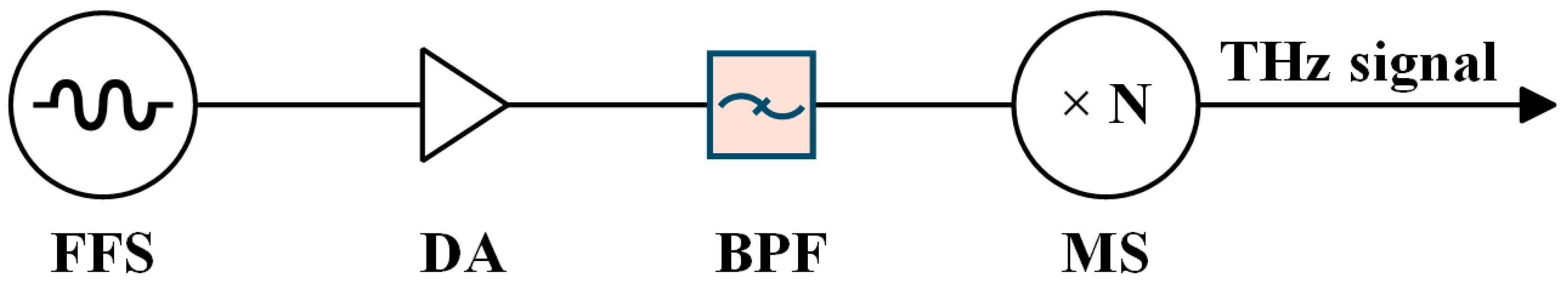
2.1. Electronic Approaches
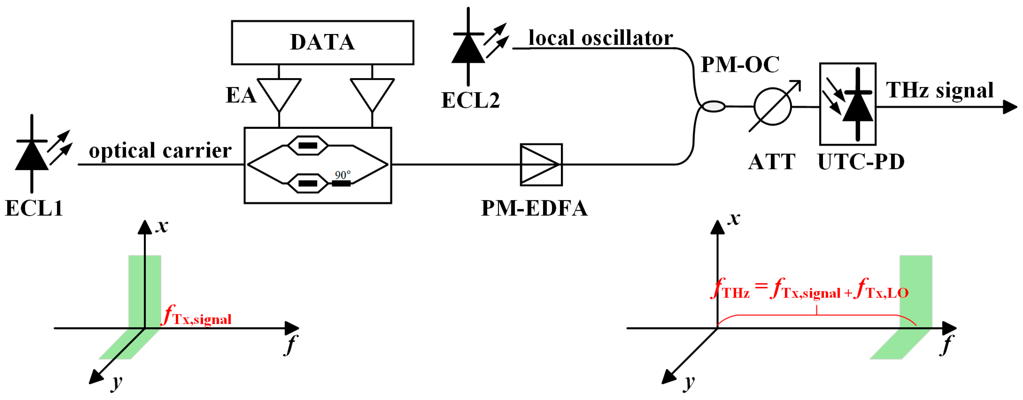
2.2. Photonic Approaches
3. Enabling Technologies for THz Communication Systems
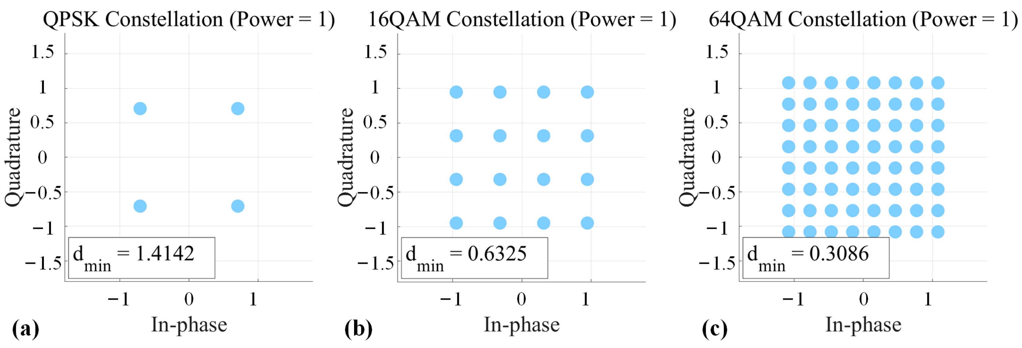
3.1. Selecting Appropriate Modulation Formats
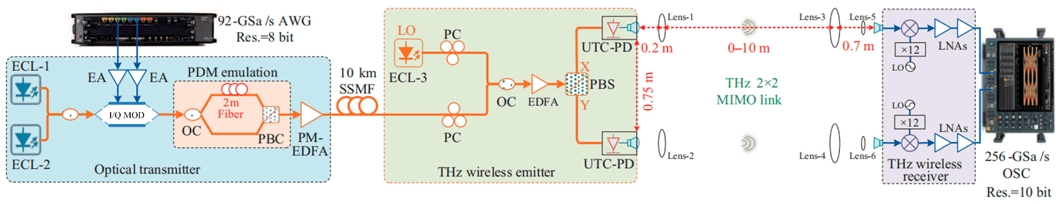
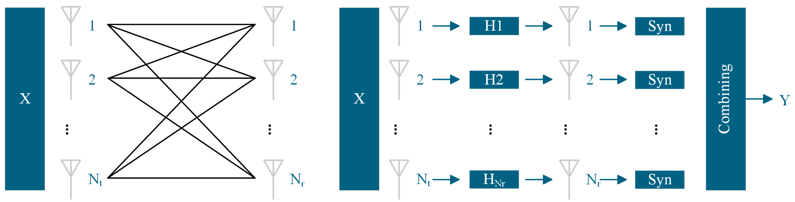
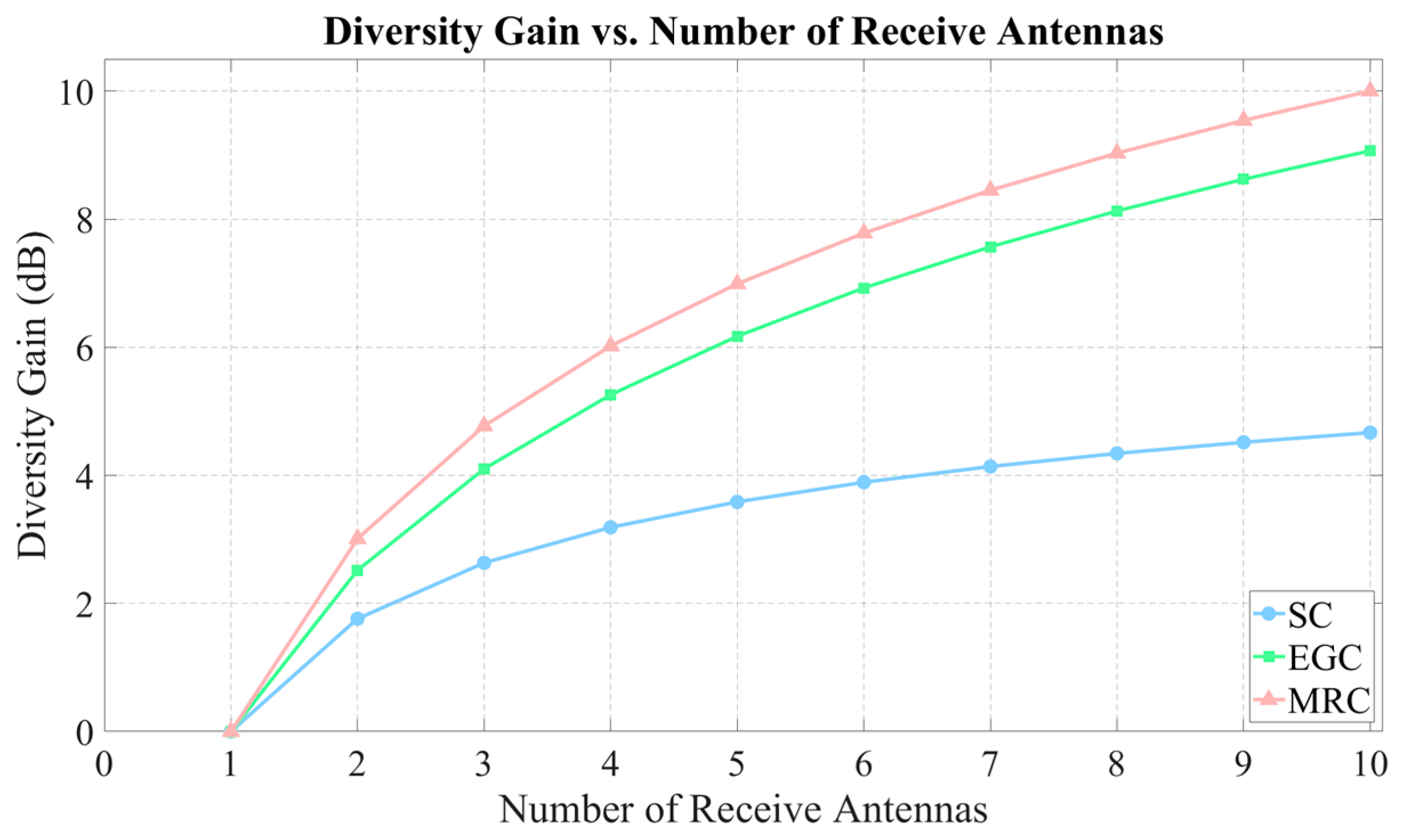
3.2. Adopting MIMO Architecture Combining Polarization Multiplexing and MRC
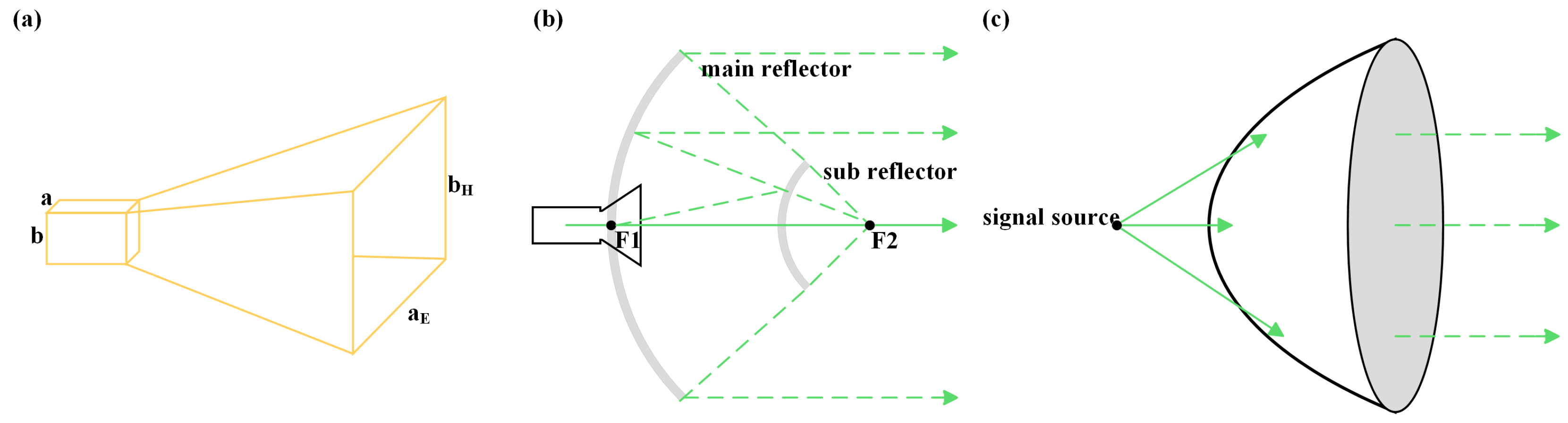
3.3. High-Gain Antennas and Lenses
3.4. Power Amplifiers
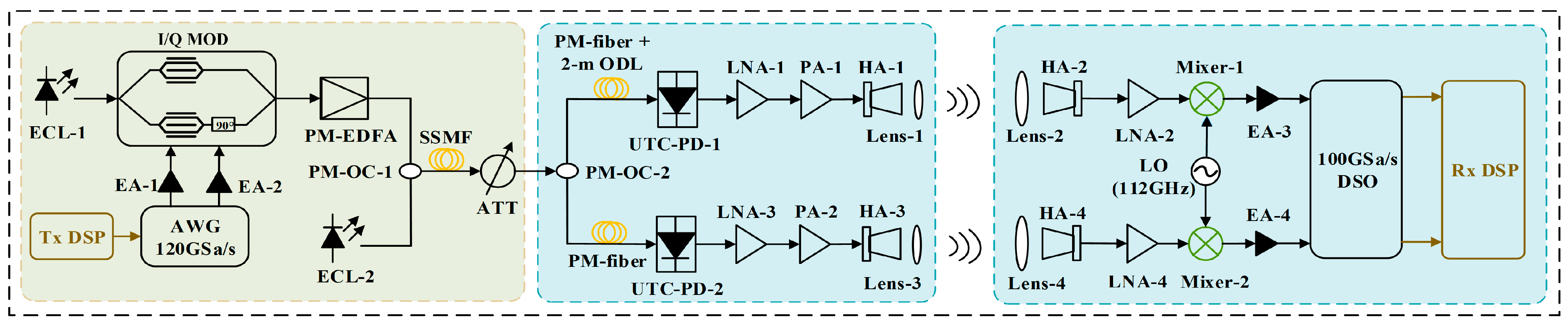
3.5. Heterodyne Coherent Detection Architecture
4. High-Sensitivity SIMO Space–Ground Communication Architecture
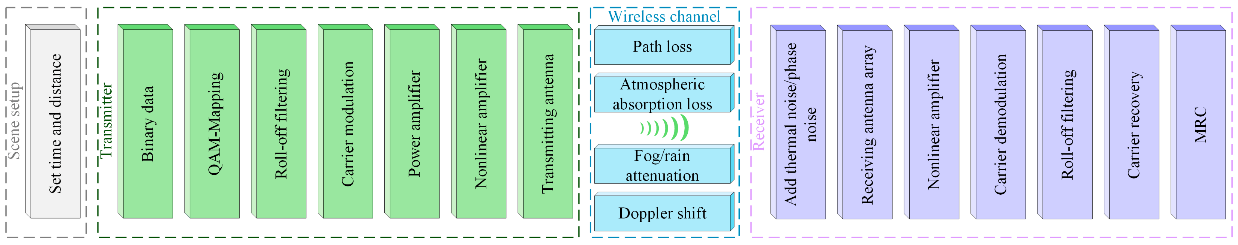
4.1. Communication Models and System Designs for Terahertz Satellite–Ground Links
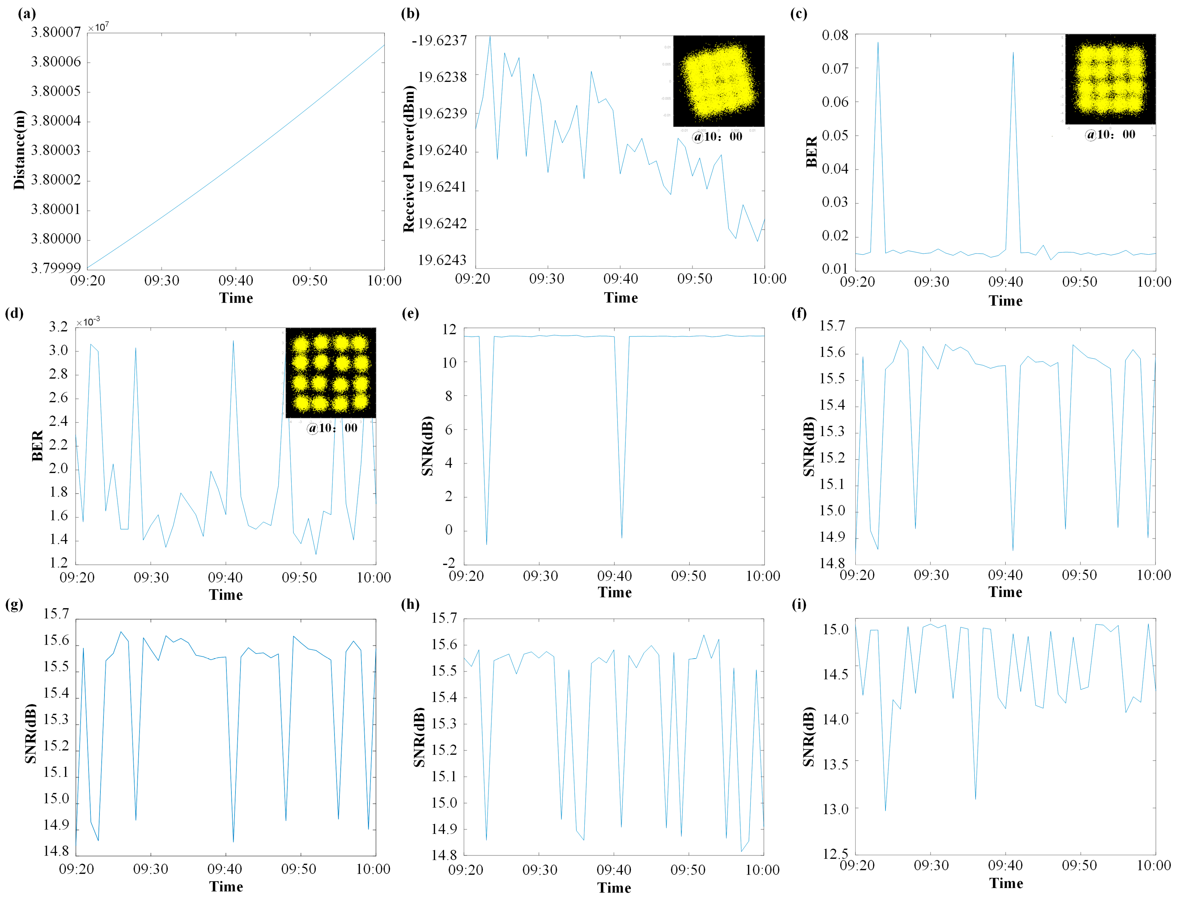
4.2. Simulation Results and Discussion
5. Conclusions
Author Contributions
Funding
Data Availability Statement
Acknowledgments
Conflicts of Interest
References
- Elayan, H.; Amin, O.; Shihada, B.; Shubair, R.M.; Alouini, M.-S. Terahertz band: The last piece of RF spectrum puzzle for communication systems. IEEE Open J. Commun. Soc. 2019, 1, 1–32. [Google Scholar] [CrossRef]
- O’Hara, J.F.; Ekin, S.; Choi, W.; Song, I. A perspective on terahertz next-generation wireless communications. Technologies 2019, 7, 43. [Google Scholar] [CrossRef]
- Rao, A.S.; SS, S.M.; Yelasani, S.; Kumar, B.S. Terahertz communications: Applications, challenges and open research issues for next generation 6G wireless networks. Int. J. Innov. Eng. Manag. Res. 2023, 12, 295–315. [Google Scholar]
- Dehos, C.; González, J.L.; De Domenico, A.; Ktenas, D.; Dussopt, L. Millimeter-wave access and backhauling: The solution to the exponential data traffic increase in 5G mobile communications systems? IEEE Commun. Mag. 2014, 52, 88–95. [Google Scholar] [CrossRef]
- Zander, J.; Mähönen, P. Riding the data tsunami in the cloud: Myths and challenges in future wireless access. IEEE Commun. Mag. 2013, 51, 145–151. [Google Scholar] [CrossRef]
- Rappaport, T.S.; Xing, Y.; Kanhere, O.; Ju, S.; Madanayake, A.; Mandal, S.; Alkhateeb, A.; Trichopoulos, G.C. Wireless communications and applications above 100 GHz: Opportunities and challenges for 6G and beyond. IEEE Access. 2019, 7, 78729–78757. [Google Scholar] [CrossRef]
- Rodenbeck, C.T.; Jaffe, P.I.; Strassner, B.H., II; Hausgen, P.E.; McSpadden, J.O.; Kazemi, H.; Shinohara, N.; Tierney, B.B.; DePuma, C.B.; Self, A.P. Microwave and millimeter wave power beaming. IEEE J. Microw. 2021, 1, 229–259. [Google Scholar] [CrossRef]
- Akyildiz, I.F.; Kak, A.; Nie, S. 6G and beyond: The future of wireless communications systems. IEEE Access 2020, 8, 133995–134030. [Google Scholar] [CrossRef]
- Tripathi, S.; Sabu, N.V.; Gupta, A.K.; Dhillon, H.S. Millimeter-wave and terahertz spectrum for 6G wireless. In 6G Mobile Wireless Networks; Springer: Berlin, Germany, 2021; pp. 83–121. [Google Scholar]
- Rizzo, L.; Federici, J.F.; Gatley, S.; Gatley, I.; Zunino, J.L.; Duncan, K.J. Comparison of terahertz, microwave, and laser power beaming under clear and adverse weather conditions. J. Infrared Millim. Terahertz Waves 2020, 41, 979–996. [Google Scholar] [CrossRef]
- Song, H.-J.; Lee, N. Terahertz communications: Challenges in the next decade. IEEE Trans. Terahertz Sci. Technol. 2021, 12, 105–117. [Google Scholar] [CrossRef]
- Federici, J.F.; Ma, J.; Moeller, L. Review of weather impact on outdoor terahertz wireless communication links. Nano Commun. Netw. 2016, 10, 13–26. [Google Scholar] [CrossRef]
- Salahdine, F.; Han, T.; Zhang, N. 5G, 6G, and Beyond: Recent advances and future challenges. Ann. Telecommun. 2023, 78, 525–549. [Google Scholar] [CrossRef]
- Wang, M.; Yu, J.; Li, W.; Wei, Y.; Yang, X.; Shi, J.; Bian, C.; Zhou, W.; Wang, K. SNR improved digital-analog radio-over-fiber scheme for a millimeter wireless fronthaul. J. Light. Technol. 2023, 42, 3531–3539. [Google Scholar] [CrossRef]
- Cherry, S. Edholm’s law of bandwidth. IEEE Spectr. 2004, 41, 58–60. [Google Scholar] [CrossRef]
- Jain, P.; Gupta, A.; Kumar, N.; Guizani, M. Dynamic and efficient spectrum utilization for 6G with THz, mmWave, and RF band. IEEE Trans. Veh. Technol. 2023, 72, 3264–3273. [Google Scholar] [CrossRef]
- Wang, M.; Yu, J.; Zhao, X.; Li, W.; Wei, Y.; Yang, X.; Shi, J.; Bian, C.; Xie, T.; Zhao, F.; et al. SNR improved digital-delta-sigma-modulation radio-over-fiber scheme for D-band 4.6-km photonics-aided wireless fronthaul. Opt. Lett. 2023, 48, 3997–4000. [Google Scholar] [CrossRef] [PubMed]
- Liu, J.; Yu, J.; Zhao, X.; Bian, C.; Yang, X.; Zhang, L.; He, W.; Long, J.; Zhang, Y.; Zhang, Y.; et al. W-band photonics-aided ISAC wireless system sharing OFDM signal as communication and sensing. In Proceedings of the Optical Fiber Communication Conference, San Diego, CA, USA, 24–28 March 2024. Tu3K. 4. [Google Scholar]
- Wang, M.; Yu, J. 104-m Wireless Transmission of 4096-QAM for Mobile Backhaul Based on Delta-Sigma Modulation in 145 GHz; Springer: Berlin, Germany, 2023. [Google Scholar]
- Wang, K.; Yu, J.; Bian, C.; Ding, J.; Zhang, J.; Zhu, M.; Yang, X.; Li, W.; Wei, Y.; Wang, M.; et al. Terahertz transmitter demonstration of the simultaneous transmission of optical and electrical terahertz band signals at 1 Tb/s bit rate and 50 m wireless delivery. Sci. China Technol. Sci. 2025, 68, 1380901. [Google Scholar] [CrossRef]
- ITU-R V.431; Nomenclature of the frequency and wavelength bands used in telecommunications. ITU: Geneva, Switzerland, 2015.
- IEEE 802.15.3d; IEEE Standard for High Data Rate Wireless Multi-Media Networks-Amendment 2: 100 Gb/s Wireless Switched Point-to-Point Physical Layer. IEEE: New York, NY, USA, 2017.
- Petrov, V.; Kurner, T.; Hosako, I. IEEE 802.15.3d: First Standardization Efforts for Sub-Terahertz Band Communications toward 6G. IEEE Commun. Mag. 2020, 58, 28–33. [Google Scholar] [CrossRef]
- Banerjee, A.; Zhang, L.; Wang, H.; Wambacq, P. Sub-THz and THz Signal Generation Using Photonic and Electronic Techniques (Invited Paper). In Proceedings of the IEEE MTT-S International Microwave Conference on Hardware and Systems for 5G and Beyond (IMC-5G), Atlanta, GA, USA, 15–16 August 2019; pp. 1–3. [Google Scholar]
- Freeman, J.R.; Brewer, A.; Madéo, J.; Cavalié, P.; Dhillon, S.S.; Tignon, J.; Beere, H.E.; Ritchie, D.A. Heterogeneous THz Quantum Cascade Lasers: Broadband Operation. In Proceedings of the International Conference on Infrared, Millimeter, and Terahertz Waves, Houston, TX, USA, 2–7 October 2011; pp. 1–2. [Google Scholar]
- Guo, H.; Guo, K.; Lin, Z.; Shum, K.M.; Chan, C.H. A 190-217-GHz Frequency Multiplier Chain With 13.2 dB Conversion Gain in 65-nm CMOS. IEEE Trans. Circuits Syst. II Express Briefs 2024, 71, 4859–4863. [Google Scholar] [CrossRef]
- Freudenstein, J.; Borsch, M.; Meierhofer, M.; Afanasiev, D.; Schmid, C.P.; Sandner, F.; Liebich, M.; Girnghuber, A.; Knorr, M.; Kira, M.; et al. Attoclocking Delocalized Bloch Electrons with Multi-Terahertz Fields. In Proceedings of the International Conference on Infrared, Millimeter, and Terahertz Waves (IRMMW-THz), Montreal, QC, Canada, 17–22 September 2023; pp. 1–2. [Google Scholar]
- Razeghi, M.; Lu, Q.Y.; Bandyopadhyay, N.; Slivken, S.; Bai, Y. Room Temperature Compact THz Sources Based on Quantum Cascade Laser Technology. In Proceedings of the SPIE Conference on Terahertz Emitters, Receivers, and Applications IV, San Diego, CA, USA, 25–26 August 2013; Volume 8846, p. 884602. [Google Scholar]
- Ren, Y.; Wallis, R.; Jessop, D.S.; Degl’Innocenti, R.; Klimont, A.; Beere, H.E.; Ritchie, D.A. Fast Terahertz Imaging Using a Quantum Cascade Amplifier. Appl. Phys. Lett. 2015, 107, 011107. [Google Scholar] [CrossRef]
- Halbauer, H.; Wild, T. Towards Power Efficient 6G Sub-THz Transmission. In Proceedings of the Joint European Conference on Networks and Communications&6G Summit (EuCNC/6G Summit), Porto, Portugal, 8–11 June 2021; pp. 25–30. [Google Scholar]
- Song, H.-J.; Nagatsuma, T. Present and future of terahertz communications. IEEE Trans. Terahertz Sci. Technol. 2011, 1, 256–263. [Google Scholar] [CrossRef]
- Wu, Y.; Singh, S.; Taleb, T.; Roy, A.; Dhillon, H.S.; Kanagarathinam, M.R.; De, A. 6G Mobile Wireless Networks; Springer: Berlin, Germany, 2021. [Google Scholar]
- Sarieddeen, H.; Alouini, M.-S.; Al-Naffouri, T.Y. An overview of signal processing techniques for terahertz communications. Proc. IEEE 2021, 109, 1628–1665. [Google Scholar] [CrossRef]
- Tan, J.; Long, J.; Yu, J.; Yang, X.; Liu, J.; Tian, P.; Xu, S.; Han, Y.; Zhang, B.; Zhang, Y. 4096-QAM Signal Transmission by An IM/DD System at THz Band Using Delta-Sigma Modulation. IEEE Photonics Technol. Lett. 2024; in press. [Google Scholar] [CrossRef]
- Zhao, X.; Yu, J.; Yang, X.; Wei, Y.; Li, W.; Tan, J.; Wang, M.; Zhang, Q.; Zhang, B.; Bian, C.; et al. D-band 4600 m wireless transmission with rates exceeding 100 Gbit/s based on photonics aided technologies. Sci. China 2024, 67, 2968–2970. [Google Scholar] [CrossRef]
- Wang, M.; Yu, J.; Zhao, X.; Yang, X.; Bian, C.; Zhang, Q.; Zhou, W.; Wang, K.; Li, W. First Demonstration of OTFS in a D-band Indoor Wireless Communication System Based on Photonics-aided Scheme. In Proceedings of the Optical Fiber Communication Conference, San Diego, CA, USA, 23–27 March 2025. M1I. 2. [Google Scholar]
- Wang, M.; Yu, J.; Zhao, X.; Zhou, W.; Chen, J.; Yang, X.; Bian, C.; Wei, Y.; Zhang, Q.; Han, Y.; et al. Research on Orthogonal Time Frequency Space in a 125-GHz mmWave Indoor Wireless Communication System. J. Light. Technol. 2025, 43, 5762–5772. [Google Scholar] [CrossRef]
- Erdem, M.; Saleem, A.; Gurbuz, O.; Ecemis, C.; Saeed, A. A simple analytical model for THz band path loss. IEEE Commun. Lett. 2023, 27, 996–1000. [Google Scholar] [CrossRef]
- Abbasi, N.A.; Hariharan, A.; Nair, A.M.; Molisch, A.F. Channel measurements and path loss modeling for indoor THz communication. In Proceedings of the 14th European Conference on Antennas and Propagation, Copenhagen, Denmark, 15–20 March 2020; pp. 1–5. [Google Scholar]
- Han, C.; Gao, W.; Yang, N.; Jornet, J.M. Molecular absorption effect: A double-edged sword of terahertz communications. IEEE Wirel. Commun. 2022, 30, 140–146. [Google Scholar] [CrossRef]
- Shi, J.; Wang, Y.; Zhang, J.; Zhao, X.; Zhu, M.; Zhou, W.; Yu, J. Beyond 500 GHz THz wireless links based on heterodyne photomixing and absolute operation pruned two-stage MIMO–volterra. IEEE Trans. Terahertz Sci. Technol. 2024, 14, 364–376. [Google Scholar] [CrossRef]
- Kokkoniemi, J.; Lehtomäki, J.; Juntti, M. A discussion on molecular absorption noise in the terahertz band. Nano Commun. Netw. 2016, 8, 35–45. [Google Scholar] [CrossRef]
- Hecht, J. History of gas lasers, Part 1-Continuous wave gas lasers. Opt. Photonics News. 2010, 21, 16–23. [Google Scholar] [CrossRef]
- Nagatsuma, T.; Hirata, A.; Kukutsu, N.; Kado, Y. Multiplexed transmission of uncompressed HDTV signals using 120-GHz-band millimeter-wave wireless link. In Proceedings of the International Topical Meeting on Microwave Photonics, Victoria, BC, Canada, 3–5 October 2007; pp. 237–240. [Google Scholar]
- Hirata, A.; Kosugi, T.; Takahashi, H.; Takeuchi, J.; Togo, H.; Yaita, M.; Kukutsu, N.; Aihara, K.; Murata, K.; Sato, Y.; et al. 120-GHz-band wireless link technologies for outdoor 10-Gbit/s data transmission. IEEE Trans. Microw. Theory Tech. 2012, 60, 881–895. [Google Scholar] [CrossRef]
- Mukherjee, P.; Gupta, B. Terahertz (THz) frequency sources and antennas-A brief review. Int. J. Infrared Millim. Waves 2008, 29, 1091–1102. [Google Scholar] [CrossRef]
- Montanaro, A.; Piccinini, G.; Mišeikis, V.; Sorianello, V.; Giambra, M.A.; Soresi, S.; Giorgi, L.; D’Errico, A.; Watanabe, K.; Taniguchi, T.; et al. Sub-THz Wireless Transmission Based on Graphene-Integrated Optoelectronic Mixer. Nat. Commun. 2023, 14, 6471. [Google Scholar] [CrossRef] [PubMed]
- Han, R.; Hu, Z.; Wang, C.; Holloway, J.; Yi, X.; Kim, M.; Mawdsley, J. Filling the gap: Silicon terahertz integrated circuits offer our best bet. IEEE Microw. Mag. 2019, 20, 80–93. [Google Scholar] [CrossRef]
- Mei, X.; Yoshida, W.; Lange, M.; Lee, J.; Zhou, J.; Liu, P.-H.; Leong, K.; Zamora, A.; Padilla, J.; Sarkozy, S.; et al. First demonstration of amplification at 1 THz using 25-nm InP high electron mobility transistor process. IEEE Electron Device Lett. 2015, 36, 327–329. [Google Scholar] [CrossRef]
- Hacker, J.; Seo, M.; Young, A.; Griffith, Z.; Urteaga, M.; Reed, T.; Rodwell, M. THz MMICs based on InP HBT technology. In Proceedings of the IEEE MTT-S International Microwave Symposium, Anaheim, CA, USA, 23–28 May 2010; pp. 1126–1129. [Google Scholar]
- Leuther, A.; Tessmann, A.; Doria, P.; Ohlrogge, M.; Seelmann-Eggebert, M.; Maßler, H.; Schlechtweg, M.; Ambacher, O. 20 nm metamorphic HEMT technology for terahertz monolithic integrated circuits. In Proceedings of the 9th European Microwave Integrated Circuit Conference, Rome, Italy, 6–7 October 2014; pp. 84–87. [Google Scholar]
- Hamza, K.H.; Nirmal, D. A review of GaN HEMT broadband power amplifiers. AEU Int. J. Electron. Commun. 2020, 116, 153040. [Google Scholar] [CrossRef]
- Crupi, G.; Vadalà, V.; Colantonio, P.; Cipriani, E.; Caddemi, A.; Vannini, G.; Schreurs, D.M. Empowering GaN HEMT models: The gateway for power amplifier design. Int. J. Numer. Model. Electron. Netw. Devices Fields. 2017, 30, e2125. [Google Scholar] [CrossRef]
- Komiak, J.J. GaN HEMT: Dominant force in high-frequency solid-state power amplifiers. IEEE Microw. Mag. 2015, 16, 97–105. [Google Scholar] [CrossRef]
- Samoska, L.A. An Overview of Solid-State Integrated Circuit Amplifiers in the Submillimeter-Wave and THz Regime. IEEE Trans. Terahertz Sci. Technol. 2011, 1, 9–24. [Google Scholar] [CrossRef]
- Hacker, J.; Urteaga, M.; Seo, M.; Skalare, A.; Lin, R. InP HBT Amplifier MMICs Operating to 0.67 THz. In Proceedings of the IEEE MTT-S International Microwave Symposium Digest (MTT), Seattle, WA, USA, 2–7 June 2013; pp. 1–3. [Google Scholar]
- Castro, C.; Elschner, R.; Merkle, T.; Schubert, C.; Freund, R. 100 Gb/s real-time transmission over a THz wireless fiber extender using a digital-coherent optical modem. In Proceedings of the Optical Fiber Communication Conference, San Diego, CA, USA, 8–12 March 2020. M4I. 2. [Google Scholar]
- Yu, J.; Li, X.; Zhou, W. Tutorial: Broadband fiber-wireless integration for 5G+ communication. APL Photonics 2018, 3, 111101. [Google Scholar] [CrossRef]
- Yu, J. Photonics-assisted millimeter-wave wireless communication. IEEE J. Quantum Electron. 2017, 53, 1–17. [Google Scholar] [CrossRef]
- Wang, M.; Yu, J.; Zhao, X.; Yang, X.; Wei, Y.; Bian, C.; Han, Y.; Tian, P.; Xu, S.; Zhou, W.; et al. Demonstration of 1.2-km D-band Wireless Fronthaul using Digital-Differential-PCM Scheme. IEEE Photonics Technol. Lett. 2025, 37, 183–186. [Google Scholar] [CrossRef]
- Li, W.; Yu, J.; Wang, Y.; Wang, F.; Zhu, B.; Zhou, W.; Zhao, F.; Yu, J. Photonics-based high-speed long-distance fiber-wireless-integration communication at the W-band. Sci. China Inf. Sci. 2023, 66, 127301. [Google Scholar] [CrossRef]
- Zhu, M.; Zhang, J.; Liu, X.; Hua, B.; Cai, Y.; Ding, J.; Lei, M.; Zou, Y.; Tian, L.; Wang, Y.; et al. Photonics-assisted THz wireless transmission with air interface user rate of 1-Tbps at 330–500 GHz band. Sci. China Inf. Sci. 2023, 66, 199302. [Google Scholar] [CrossRef]
- Li, X.; Yu, J.; Chang, G.-K. Photonics-assisted technologies for extreme broadband 5G wireless communications. J. Light. Technol. 2019, 37, 2851–2865. [Google Scholar] [CrossRef]
- Wang, M.; Yu, J.; Zhao, X.; Wang, C.; Long, J.; Zhao, F.; Zhou, W.; Wang, K. Non-uniform-digital-analog radio-over-fiber scheme for future fronthaul based on a low-complexity 4-fold symmetric non-uniform quantization method. J. Light. Technol. 2024, 42, 6798–6807. [Google Scholar] [CrossRef]
- Singya, P.K.; Shaik, P.; Kumar, N.; Bhatia, V.; Alouini, M.-S. A survey on higher-order QAM constellations: Technical challenges, recent advances, and future trends. IEEE Open J. Commun. Soc. 2021, 2, 617–655. [Google Scholar] [CrossRef]
- Jia, Z.; Chien, H.-C.; Zhang, J.; Cai, Y.; Yu, J. Performance comparison of dual-carrier 400G with 8/16/32-QAM modulation formats. IEEE Photonics Technol. Lett. 2015, 27, 1414–1417. [Google Scholar] [CrossRef]
- Zhou, W.; Wang, S.; Xu, S.; Wang, Q.; Ou, Z.; Ma, Y.; Lin, J.; Ge, J.; Yu, J. Frequency-Domain Complex-Valued NN Equalizer Based on Deep Reinforcement Learning for Photonics-Assisted W-Band 16QAM-DMT Signals System Over 50 m. J. Light. Technol. 2024, 43, 2651–2663. [Google Scholar] [CrossRef]
- Yang, X.; Yu, J.; Zhao, X.; Wei, Y.; Li, W.; Shi, J.; Bian, C.; Zheng, T.; Zhao, F.; Zhou, W.; et al. 41.7-Gb/s D-band signals wireless delivery over 4.6 km distance based on photonics-aided technology. Opt. Laser Technol. 2024, 174, 110660. [Google Scholar] [CrossRef]
- Jia, S.; Zhang, L.; Wang, S.; Li, W.; Qiao, M.; Lu, Z.; Idrees, N.M.; Pang, X.; Hu, H.; Zhang, X.; et al. 2 × 300 Gbit/s line rate PS-64QAM-OFDM THz photonic-wireless transmission. J. Light. Technol. 2020, 38, 4715–4721. [Google Scholar] [CrossRef]
- Tong, W.; Ding, J.; Meng, J.; Xu, X.; Zhang, J.; Hua, B.; Cai, Y.; Lei, M.; Xin, Z.; Yu, J.; et al. 400-Gbit/s Net Rate DP-OFDM Signals Fiber-THz-Fiber Seamless Transmission Employing Hybrid Time-Frequency-Polarization Domain Equalization. J. Light. Technol. 2024, 42, 5148–5155. [Google Scholar] [CrossRef]
- Wang, M.; Yu, J.; Zhao, X.; Zhu, B.; Wang, C.; Zhou, W.; Wang, K. SNR improved truncated-digital-DSM radio-over-fiber scheme for future mobile fronthaul. J. Light. Technol. 2023, 42, 1934–1940. [Google Scholar] [CrossRef]
- Tong, W.; Ding, J.; Zhu, M.; Xin, Z.; Yang, X.; Xie, Z.; Meng, J.; Cai, Y.; Hua, B.; Zhang, J.; et al. 200-m Photonics-Aided Terahertz Wireless Transmission of 253-Gbit/s DP-OFDM Signals Utilizing Multidimensional Nonlinear Equalization. J. Light. Technol. 2024, 43, 214–221. [Google Scholar] [CrossRef]
- Wang, M.; Yu, J.; Zhao, X.; Bian, C.; Zhou, W.; Wang, K. K-means non-uniform-quantization digital–analog radio-over-fiber scheme for THz-band photonics-aided wireless fronthaul. Opt. Lett. 2024, 49, 2801–2804. [Google Scholar] [CrossRef] [PubMed]
- Wang, K.; Zhu, B.; Wei, Y.; Wang, C.; Zhou, W.; Zhao, L.; Yu, J. Demonstration of DSM-1024QAM Signals Transmission in A 96 Channel WDM-FSO System for Mobile Fronthaul; Springer: Berlin, Germany, 2023. [Google Scholar]
- Wei, Y.; Yu, J.; Zhao, X.; Yang, X.; Wang, M.; Li, W.; Tian, P.; Han, Y.; Zhang, Q.; Tan, J.; et al. Demonstration of a photonics-aided 4600-m wireless transmission system in the sub-THz band. J. Light. Technol. 2024, 42, 8564–8576. [Google Scholar] [CrossRef]
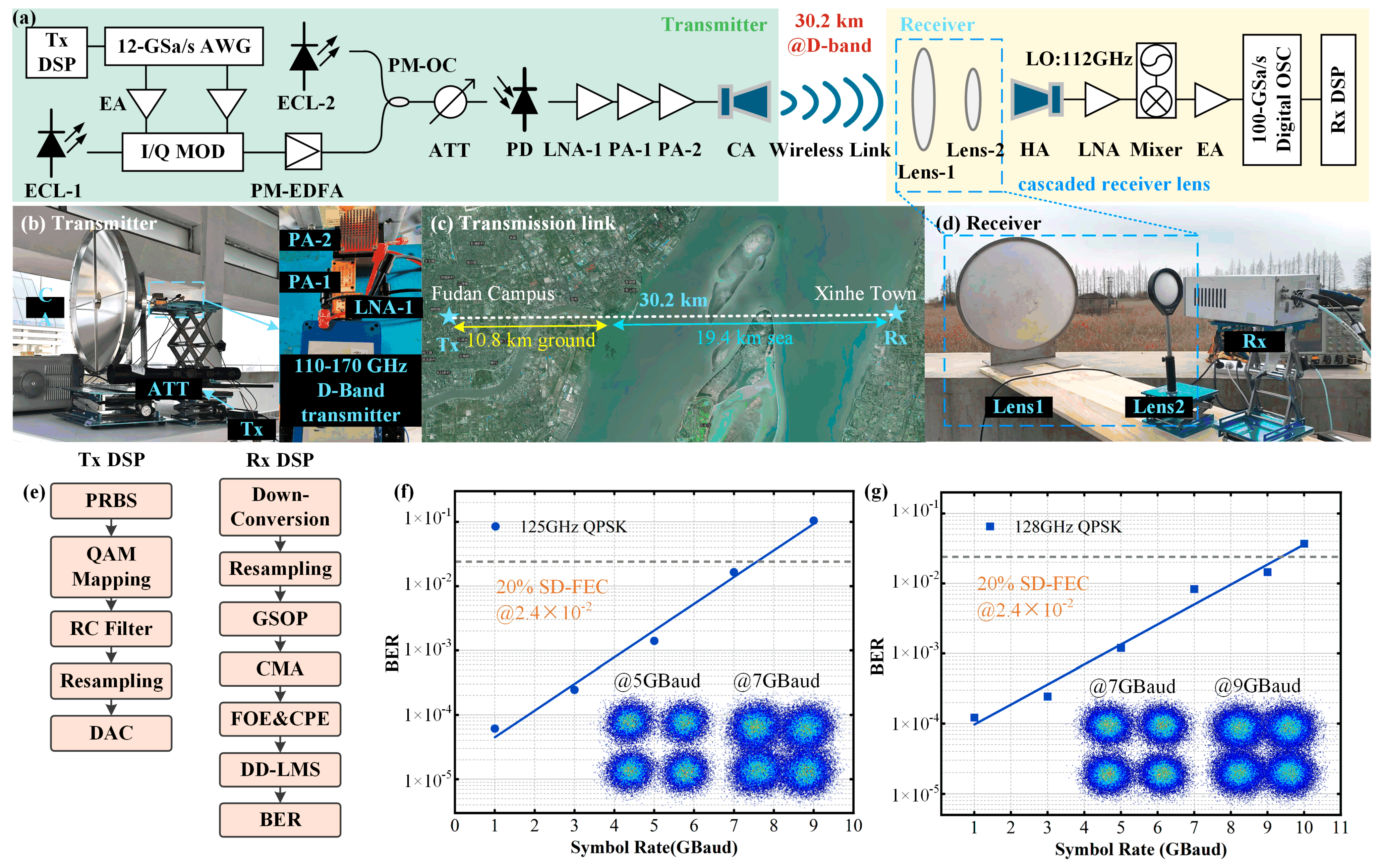
- Wei, Y.; Yang, X.; Yu, J.; Zhao, X.; Wang, M.; Tan, J.; Li, W.; Zhao, F.; Bian, C.; Ma, H.; et al. Experimental demonstration of D-band signals wireless transmission over 30 km. Sci. China Technol. Sci. 2025, 68, 1280901. [Google Scholar] [CrossRef]
- Nagatsuma, T.; Horiguchi, S.; Minamikata, Y.; Yoshimizu, Y.; Hisatake, S.; Kuwano, S.; Yoshimoto, N.; Terada, J.; Takahashi, H. Terahertz wireless communications based on photonics technologies. Opt. Express 2013, 21, 23736–23747. [Google Scholar] [CrossRef] [PubMed]
- Jornet, J.M.; Akyildiz, I.F. Channel modeling and capacity analysis for electromagnetic wireless nanonetworks in the terahertz band. IEEE Trans. Wirel. Commun. 2011, 10, 3211–3221. [Google Scholar] [CrossRef]
- Li, W.; Wang, K.; Sang, B.; Yu, J. Dual-channel WDM fiber-wireless integrated terahertz transmission system. Acta Electron. Sin. 2022, 50, 2311–2317. [Google Scholar]
- Long, J.; Yu, J.; Wang, C.; Zhang, L.; Sang, B.; Wu, Y.; Yang, X.; Wei, Y.; Wang, K.; Zhou, W.; et al. 510-Gbps 322-GHz photonics-aided terahertz wireless transmission system with MIMO embedded adaptive phase recovery equalizer. IEEE Trans. Microw. Theory Tech. 2024, 73, 3597–3607. [Google Scholar] [CrossRef]
- Kürner, T.; Priebe, S. Towards THz communications-status in research, standardization and regulation. J. Infrared Millim. Terahertz Waves 2014, 35, 53–62. [Google Scholar] [CrossRef]
- Paulraj, A.J.; Gore, D.A.; Nabar, R.U.; Bolcskei, H. An overview of MIMO communications-a key to gigabit wireless. Proc. IEEE 2004, 92, 198–218. [Google Scholar] [CrossRef]
- Li, W.; Yu, J.; Zhu, B.; Zhang, J.; Zhu, M.; Wang, C.; Zhou, W.; Xie, T.; Yu, J.; Zhao, F. Photonics 60 GBaud PDM-16QAM fiber-wireless 2 × 2 MIMO delivery at THz-band. Chin. Opt. Lett. 2023, 21, 073901. [Google Scholar] [CrossRef]
- Wang, C.; Yu, J.; Zhang, J.; Zhu, M.; Tan, Y.; Wang, K.; Ding, J.; Zhou, W.; Xie, T.; Yu, J.; et al. Beyond 300-Gbps/λ photonics-aided THz-over-fiber transmission employing MIMO single-carrier frequency-domain equalizer. Opt. Lett. 2023, 48, 1363–1366. [Google Scholar] [CrossRef] [PubMed]
- Cai, Y.; Yang, X.; Zhu, M.; Hua, B.; Xie, Z.; Tong, W.; Xin, Z.; Li, J.; Zhang, J.; Ding, J.; et al. Photonics-aided exceeding 200-Gb/s wireless data transmission over outdoor long-range 2 × 2 MIMO THz links at 300 GHz. Opt. Express. 2024, 32, 33587–33602. [Google Scholar] [CrossRef] [PubMed]
- Li, W.; Yu, J.; Ji, X.; Liu, J.; Wang, F.; Zhu, B.; Zhou, W.; Zhao, F.; Yu, J. Over 100 Gb/s mm-wave delivery with 4600 m wireless distance based on dual polarization multiplexing. Sci. China Inf. Sci. 2023, 66, 224301. [Google Scholar] [CrossRef]
- Zhang, Q.; Yu, J.; Zhao, X.; Li, W.; Wei, Y.; Yang, X.; Tan, J.; Zhang, B.; Wang, K.; Zhang, Y.; et al. 4.6-km D-band photonic-assisted terahertz wireless communication employing SIMO and MRC technology. IEEE Trans. Microw. Theory Tech. 2024, 72, 6657–6668. [Google Scholar] [CrossRef]
- Wei, Y.; Yu, J.; Wang, M.; Zhao, X.; Yang, X.; Li, W.; Tian, P.; Han, Y.; Zhang, Q.; Tan, J.; et al. Demonstration of 200 Gbps D-band Wireless Delivery in a 4.6 km 2 × 2 MIMO system. In Proceedings of the Optical Fiber Communication Conference, San Diego, CA, USA, 24–28 March 2024. M2F. 4. [Google Scholar]
- Simon, M.K.; Alouini, M.-S. Digital Communication over Fading Channels; John Wiley&Sons: Hoboken, NJ, USA, 2004. [Google Scholar]
- Zhang, Q.; Yu, J.; Zhao, X.; Li, W.; Zhu, M.; Zhang, J.; Wei, Y.; Wang, K.; Zhou, W.; Liu, B.; et al. 2 × 2 MIMO W-Band Millimeter Wireless Signal Delivery Employing CMA and MRC Technology. J. Light. Technol. 2024, 42, 4485–4492. [Google Scholar] [CrossRef]
- Zhang, Q.; Yu, J.; Li, W.; Zhang, B.; Zhou, W.; Wang, K.; Wei, Y.; Yang, X.; Wang, M.; Liu, B.; et al. Demonstration of a 200-m 300 GHz photon-assisted MIMO THz system using PDM and MRC technologies with SNR gain and coherence destruction mitigated. Sci. China Technol. Sci. 2025, 68, 1680901. [Google Scholar] [CrossRef]
- Abadal, S.; Han, C.; Jornet, J.M. Wave propagation and channel modeling in chip-scale wireless communications: A survey from millimeter-wave to terahertz and optics. IEEE Access 2019, 8, 278–293. [Google Scholar] [CrossRef]
- Sakhnini, I.; Dominic, O. Performance Comparison Between Optical Wireless and mmWave/THz RF Communications Systems. IEEE J. Sel. Areas Commun. 2025, 43, 1635–1645. [Google Scholar] [CrossRef]
- Nallappan, K.; Guerboukha, H.; Cao, Y.; Xu, G.; Nerguizian, C.; Mittleman, D.M.; Skorobogatiy, M. Terahertz Waveguides for Next Generation Communication Network: Needs, Challenges and Perspectives. In Next Generation Wireless Terahertz Communication Networks, 1st ed.; Ghafoor, S., Rehmani, M.H., Davy, A., Eds.; CRC Press: Boca Raton, FL, USA, 2021; pp. 379–410. [Google Scholar]
- Atakaramians, S.; Afshar, S.V.; Monro, T.M.; Abbott, D. Terahertz Dielectric Waveguides. Adv. Opt. Photonics 2013, 5, 169–215. [Google Scholar] [CrossRef]
- Tan, Z.; Zhang, Q.-Y.; Lei, Y.-L.; Zhao, Y.; Ding, J.-Q. Terahertz Waveguide Multiplexers: A Review. Microw. Opt. Technol. Lett. 2023, 65, 1925–1935. [Google Scholar] [CrossRef]
- Xu, R.; Gao, S.; Izquierdo, B.S.; Gu, C.; Reynaert, P.; Standaert, A.; Gibbons, G.J.; Bösch, W.; Gadringer, M.E.; Li, D. A review of broadband low-cost and high-gain low-terahertz antennas for wireless communications applications. IEEE Access. 2020, 8, 57615–57629. [Google Scholar] [CrossRef]
- He, Y.; Chen, Y.; Zhang, L.; Wong, S.-W.; Chen, Z.N. An overview of terahertz antennas. China Commun. 2020, 17, 124–165. [Google Scholar] [CrossRef]
- Maddalena, R.J. Theoretical Ratio of Beam Efficiency to Aperture Efficiency; GBT Memo: Green Bank, WV, USA, 2010. [Google Scholar]
- Lu, X.; Yu, J.; Li, W.; Zhao, X.; Zhu, M.; Zhang, J.; Yang, W.; Wang, M.; Wei, Y.; Zhang, Q.; et al. Realizing 10 Gbps Frequency Continuously Tunable D-Band Signal Transmission With 20 Kilometers Wireless Distance Based on Photon Assistance. J. Light. Technol. 2025, 43, 5709–5717. [Google Scholar] [CrossRef]
- Balanis, C.A. Antenna Theory: Analysis and Design; John Wiley&Sons: Hoboken, NJ, USA, 2016. [Google Scholar]
- Olver, A.D. Microwave Horns and Feeds; IET: London, UK, 1994; Volume 39. [Google Scholar]
- Tian, P.; Han, Y.; Li, W.; Yang, X.; Wang, M.; Yu, J. New Design Scheme for and Application of Fresnel Lens for Broadband Photonics Terahertz Communication. Sensors 2024, 24, 7592. [Google Scholar] [CrossRef] [PubMed]
- Akyildiz, I.F.; Jornet, J.M.; Han, C. Terahertz band: Next frontier for wireless communications. Phys. Commun. 2014, 12, 16–32. [Google Scholar] [CrossRef]
- Urteaga, M.; Griffith, Z.; Seo, M.; Hacker, J.; Rodwell, M.J. InP HBT technologies for THz integrated circuits. Proc. IEEE 2017, 105, 1051–1067. [Google Scholar] [CrossRef]
- Weimann, N. InP HBT technology for THz applications. In Proceedings of the IEEE International Symposium on Radio-Frequency Integration Technology, Hiroshima, Japan, 2–4 September 2020; pp. 190–192. [Google Scholar]
- Wei, Y.; Yu, J.; Wang, M.; Yang, X.; Zhang, Q.; Tan, J.; Zhang, B.; Wu, Y.; Han, Y.; Tian, P.; et al. Experimental demonstration of 220-GHz terahertz signals wireless transmission over 4.6 km. Sci. China Inf. Sci. 2025, 68, 1–3. [Google Scholar] [CrossRef]
- Wang, M.; Yu, J.; Yang, X.; Wei, Y.; Bian, C.; Zhao, X.; Tian, P.; Han, Y.; Zhang, Q.; Tan, J.; et al. Demonstration of D-Band Wireless Transmission Over 30.2 km Distance Based on Photonic-assisted Scheme. In Proceedings of the Optical Fiber Communication Conference, San Diego, CA, USA, 23–27 March 2025. W4F. 5. [Google Scholar]
- Brown, E.R.; Segovia-Vargas, D. Principles of THz direct detection. In Semiconductor Terahertz Technology: Devices and Systems at Room Temperature Operation; Wiley Online Library: Hoboken, NJ, USA, 2015; pp. 212–253. [Google Scholar]
- Zhang, L.; Yu, J.; Zhu, M.; Zhu, Z.; Yang, X.; Tan, J.; Yu, J.; Ding, J.; Zhang, J. Real-time demonstration of 27.6-Gbit/s 0.3 THz signal wireless transmission over 54 meters based on IM/envelop detection. Sci. China Technol. Sci. 2025, 68, 1480901. [Google Scholar] [CrossRef]
- Wang, M.; Yu, J.; Zhao, X.; Zhou, W.; Wang, K. SNR improved digital-cascaded-pulse-code-modulation radio-over-fiber scheme supporting 16,777,216 QAM for mobile fronthaul. J. Opt. Commun. Netw. 2023, 15, 948–957. [Google Scholar] [CrossRef]
- Yao, H.; Wang, L.; Wang, X.; Lu, Z.; Liu, Y. The space-terrestrial integrated network: An overview. IEEE Commun. Mag. 2018, 56, 178–185. [Google Scholar] [CrossRef]
- Chao, H.-C.; Comer, D.E.; Kao, O. Space and terrestrial integrated networks: Emerging research advances, prospects, and challenges. IEEE Netw. 2019, 33, 6–7. [Google Scholar] [CrossRef]
- Chen, S.; Sun, S.; Kang, S. System Integration of Terrestrial Mobile Communication and Satellite Communication—The Trends, Challenges and Key Technologies in B5G and 6G. China Commun. 2021, 17, 156–171. [Google Scholar] [CrossRef]
- Samy, R.; Yang, H.-C.; Rakia, T.; Alouini, M.-S. Space-Air-Ground FSO Networks for High-Throughput Satellite Communications. IEEE Commun. Mag. 2022, 60, 82–87. [Google Scholar] [CrossRef]
- Han, C.; Gao, W.; Yin, Z.; Yang, C.; Peng, M.; Zhang, W. Joint Communication and Radar Sensing for Terahertz Space-Air-Ground Integrated Networks (SAGIN). arXiv 2025, arXiv:2502.17811. [Google Scholar]
- Zhang, Q.; Yu, J.; Long, J.; Wang, C.; Chen, J.; Lu, X. A Hybrid RF/FSO Transmission System Based on a Shared Transmitter. Sensors 2025, 25, 2021. [Google Scholar] [CrossRef] [PubMed]
- Zhang, Q.; Yu, J.; Long, J.; Wang, C.; Chen, J.; Lu, X.; Liu, B.; Yang, X.; Wei, Y.; Zhao, F.; et al. A THz/FSO Fusion Transmission System with Shared Transmitter and Communication Link. In Proceedings of the Optical Fiber Communication Conference, San Diego, CA, USA, 23–27 March 2025. W4F. 8. [Google Scholar]


| Parameter | Value |
|---|---|
| Frequency | 300 GHz |
| Distance | 36,000 km |
| Symbol Rate | 25 GBaud |
| Symbol Length | 32,768 |
| Sampling Points per Symbol | 30 |
| Modulation Order | 16 |
| TX Antenna Diameter | 4.5 m |
| RX Antenna Diameter | 2.06 m |
| Aperture Efficiency | 0.6 |
| Number of RX Antennas | 4 |
| Transmit Power | 1 W |
Disclaimer/Publisher’s Note: The statements, opinions and data contained in all publications are solely those of the individual author(s) and contributor(s) and not of MDPI and/or the editor(s). MDPI and/or the editor(s) disclaim responsibility for any injury to people or property resulting from any ideas, methods, instructions or products referred to in the content. |
© 2025 by the authors. Licensee MDPI, Basel, Switzerland. This article is an open access article distributed under the terms and conditions of the Creative Commons Attribution (CC BY) license (https://creativecommons.org/licenses/by/4.0/).
Share and Cite
Yu, J.; Chen, J. Research on Tbps and Kilometer-Range Transmission of Terahertz Signals. Micromachines 2025, 16, 828. https://doi.org/10.3390/mi16070828
Yu J, Chen J. Research on Tbps and Kilometer-Range Transmission of Terahertz Signals. Micromachines. 2025; 16(7):828. https://doi.org/10.3390/mi16070828
Chicago/Turabian StyleYu, Jianjun, and Jiali Chen. 2025. "Research on Tbps and Kilometer-Range Transmission of Terahertz Signals" Micromachines 16, no. 7: 828. https://doi.org/10.3390/mi16070828
APA StyleYu, J., & Chen, J. (2025). Research on Tbps and Kilometer-Range Transmission of Terahertz Signals. Micromachines, 16(7), 828. https://doi.org/10.3390/mi16070828