

Cam Design and Pin Defect Detection of Cam Pin Insertion Machine in IGBT Packaging

Abstract
1. Introduction
2. Cam Design in the Pin Insertion Mechanism
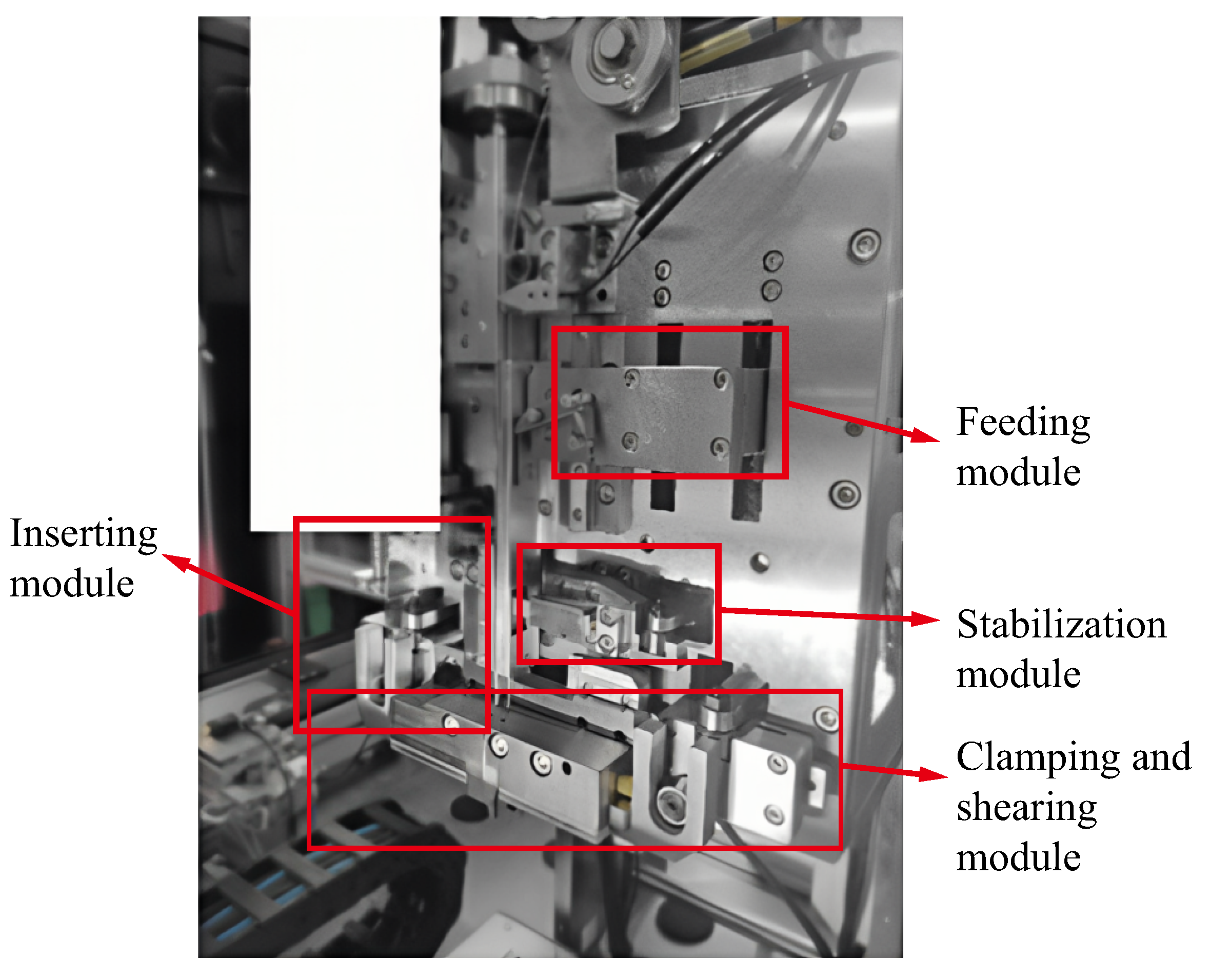
2.1. Process Decomposition
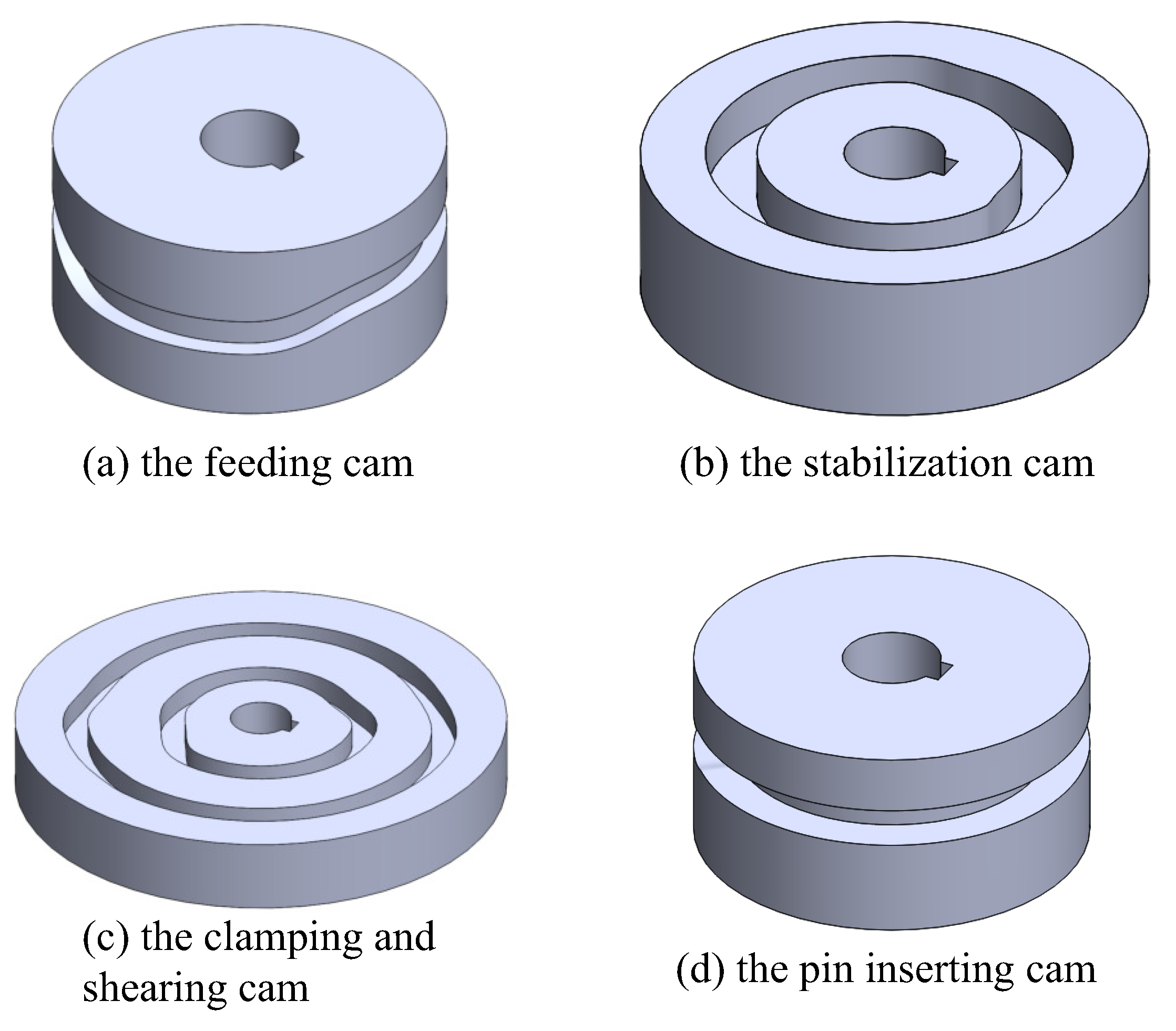
2.2. Cam Profile Curve Fitting and Solving
3. Motion Simulation Verification of Cam Pin Mechanism
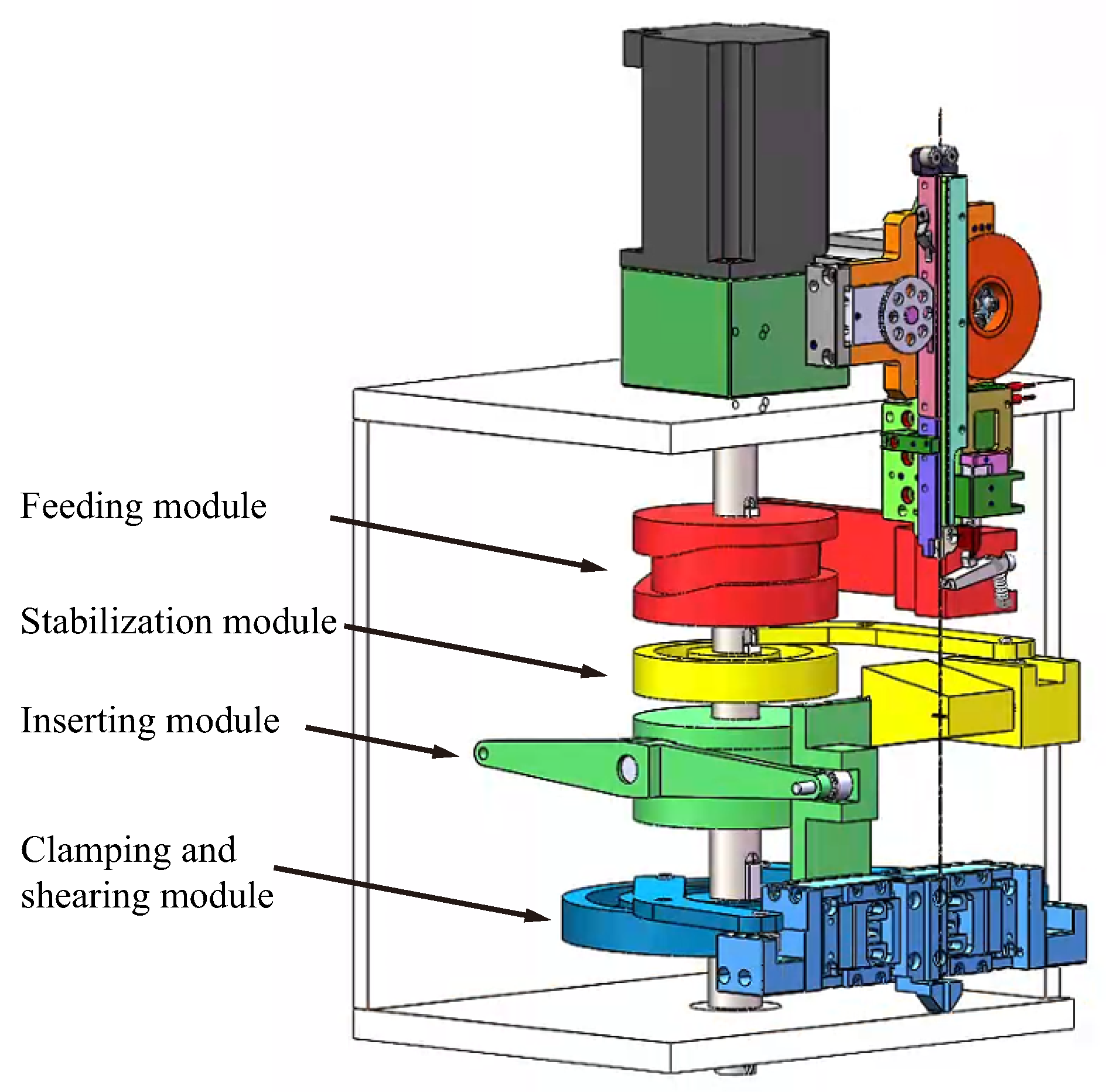
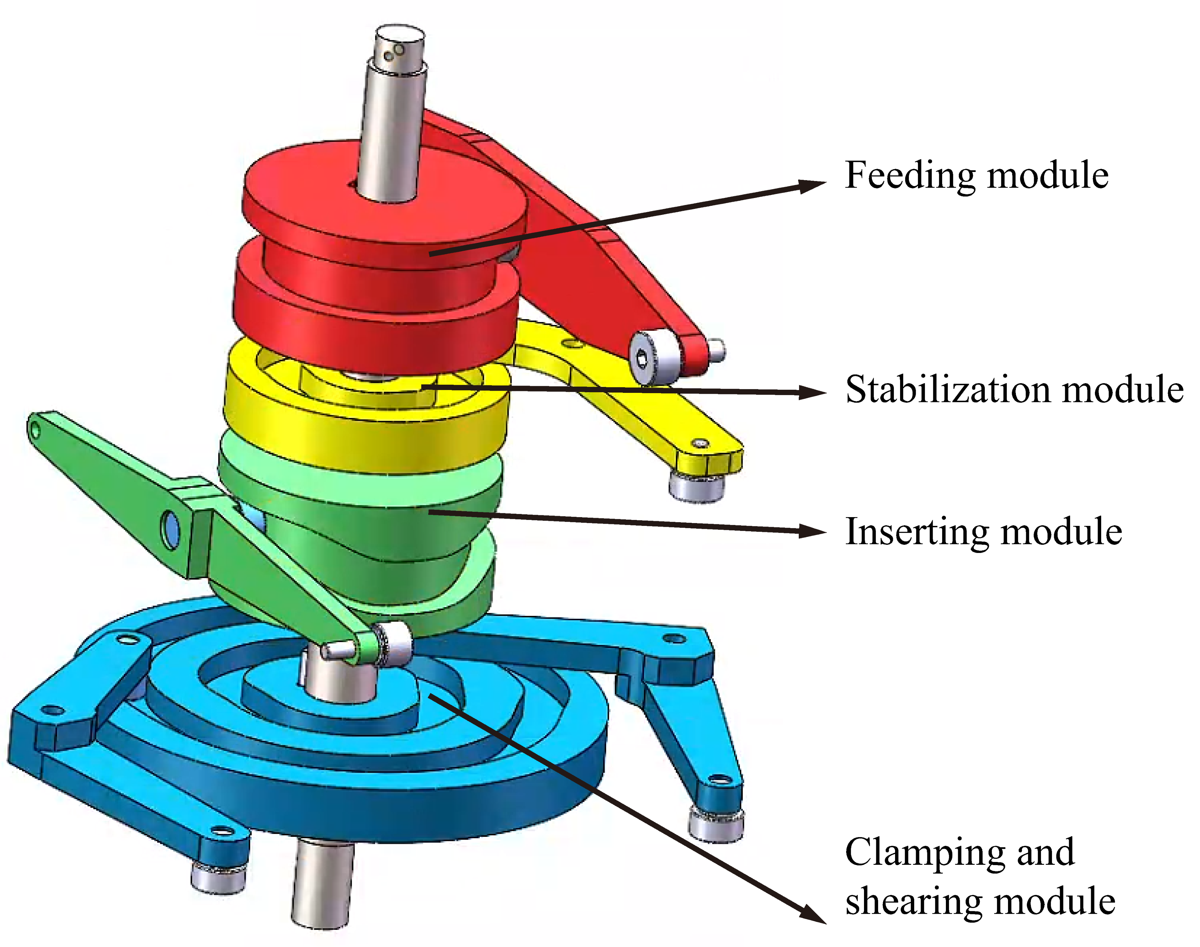
3.1. Simulation Model Construction
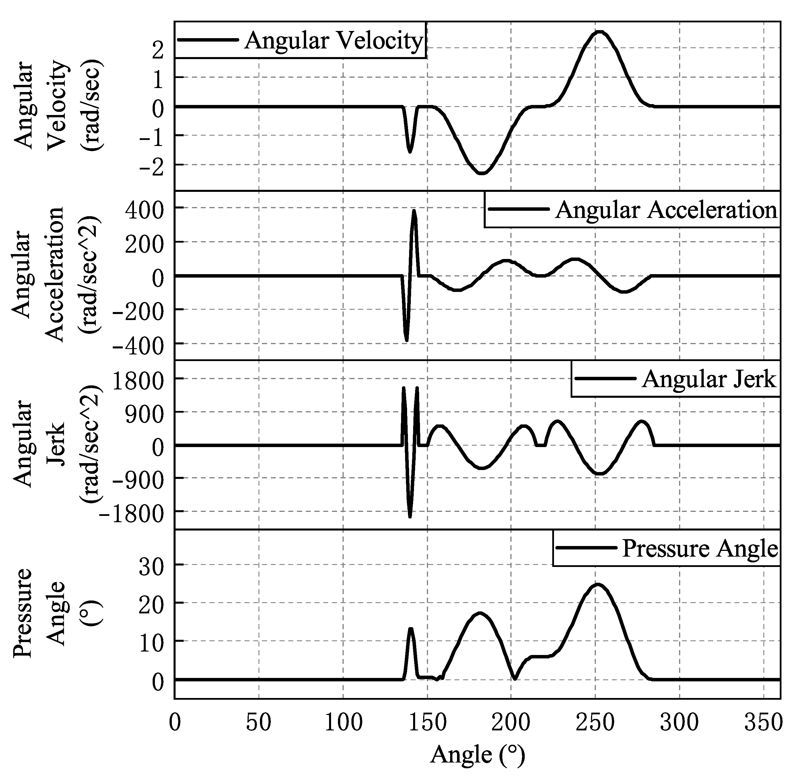
3.2. Analysis of Simulation Results
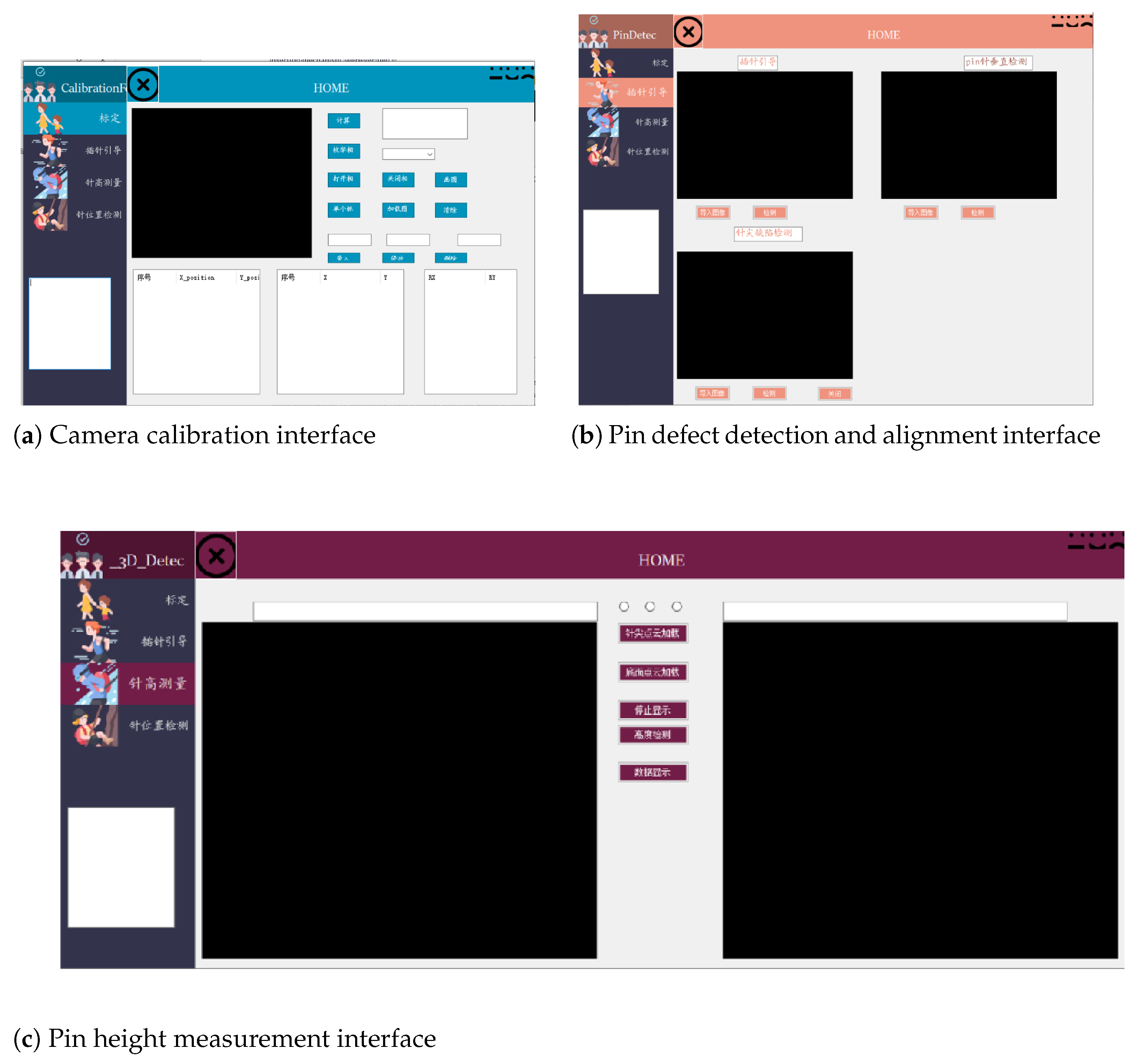
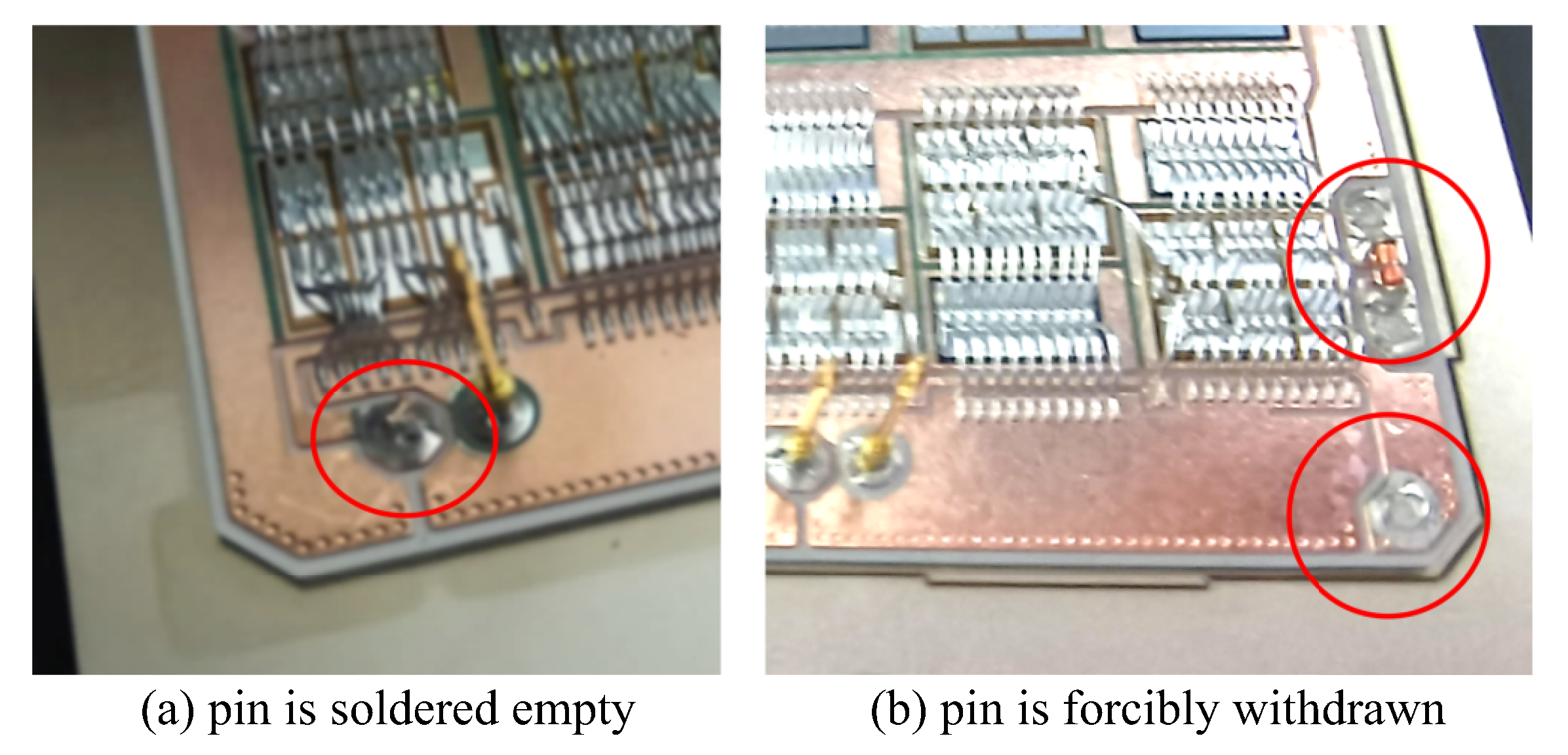
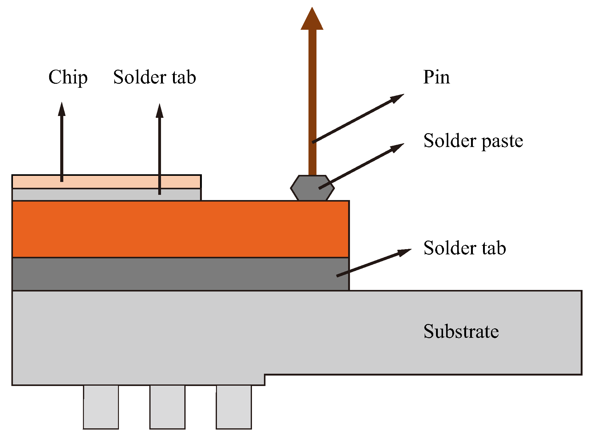
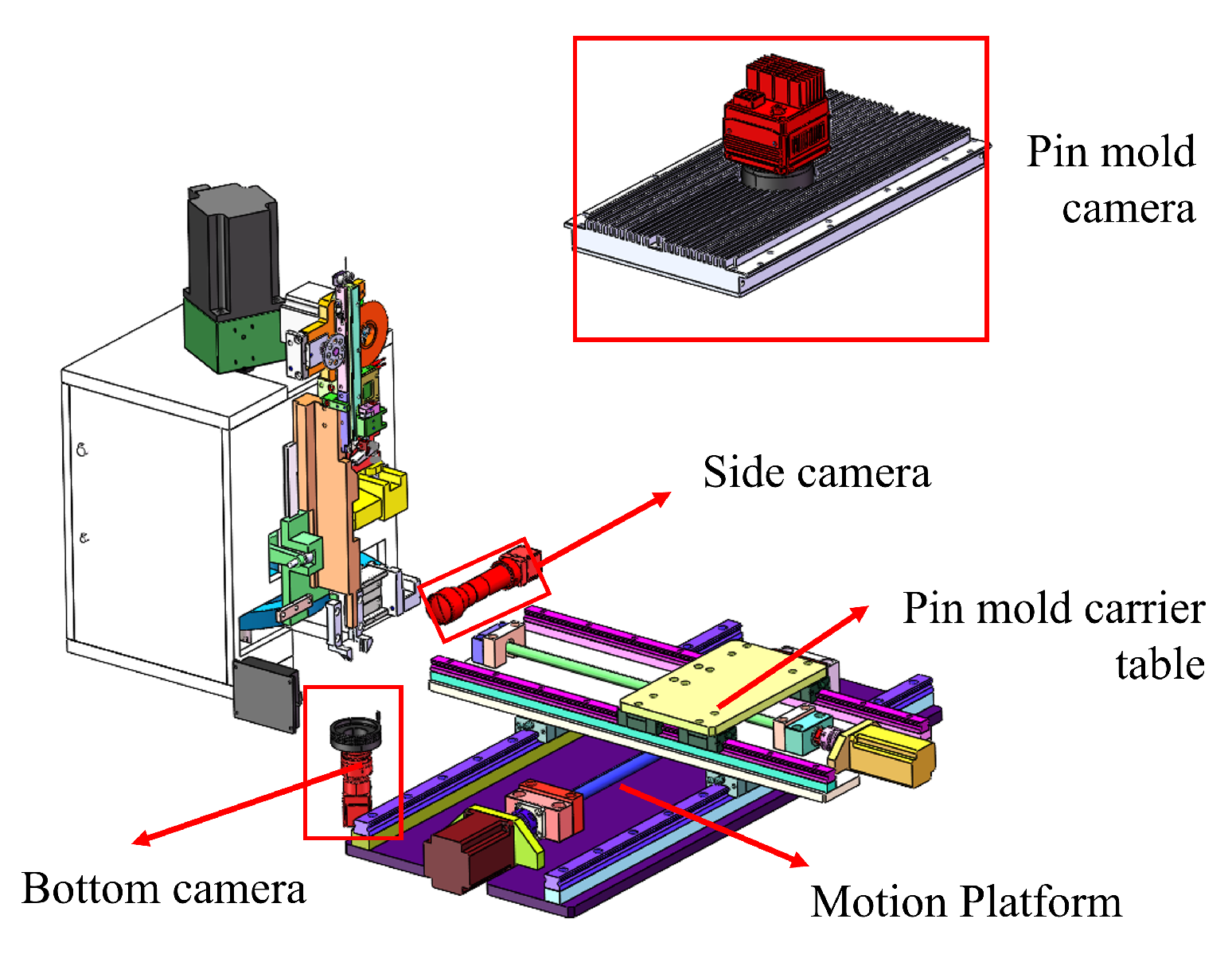
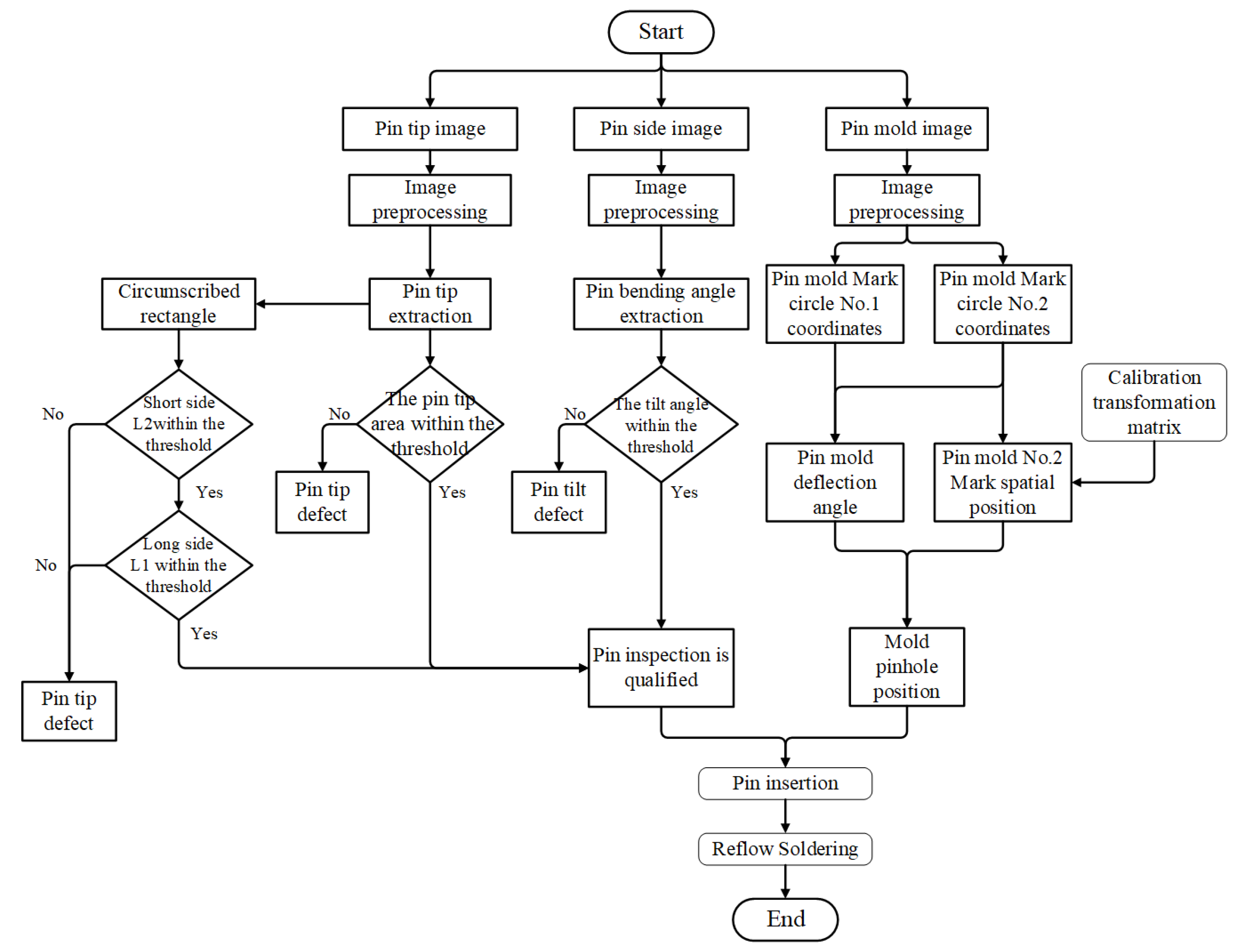
4. IGBT Pin Defect Detection and Pin Insertion Alignment
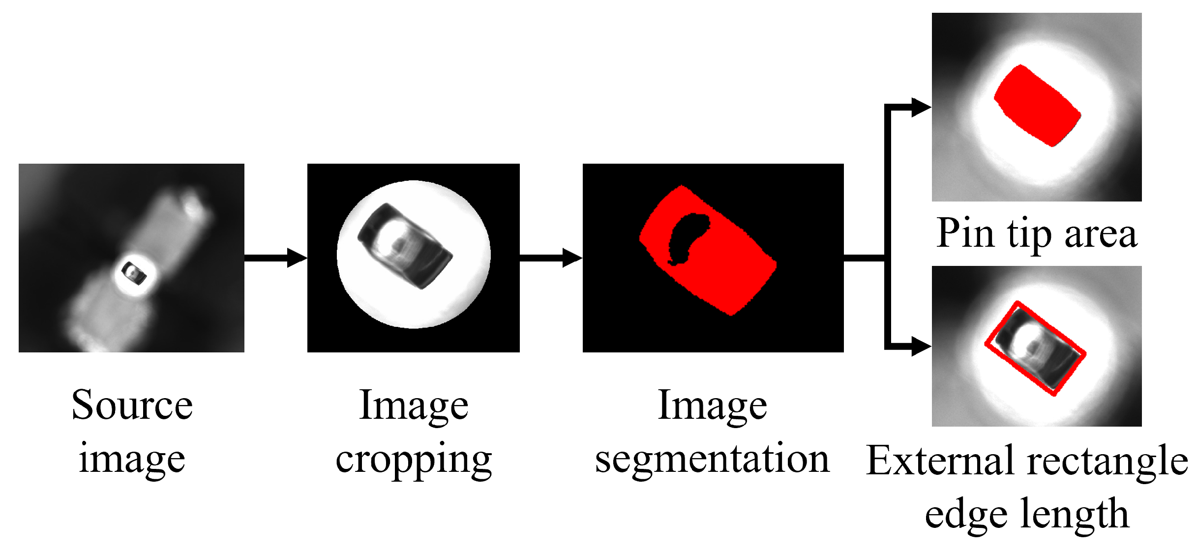
4.1. Pin Tip Defect Detection
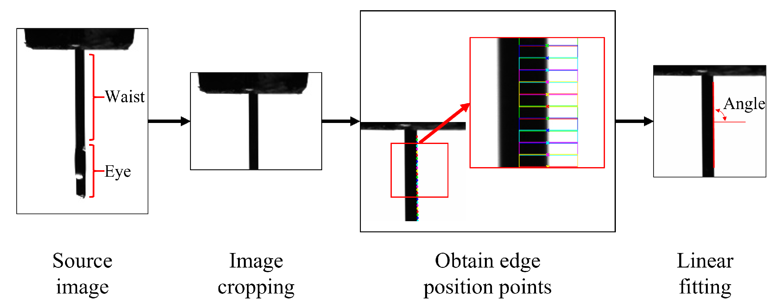
4.2. Pin Tilt Detection
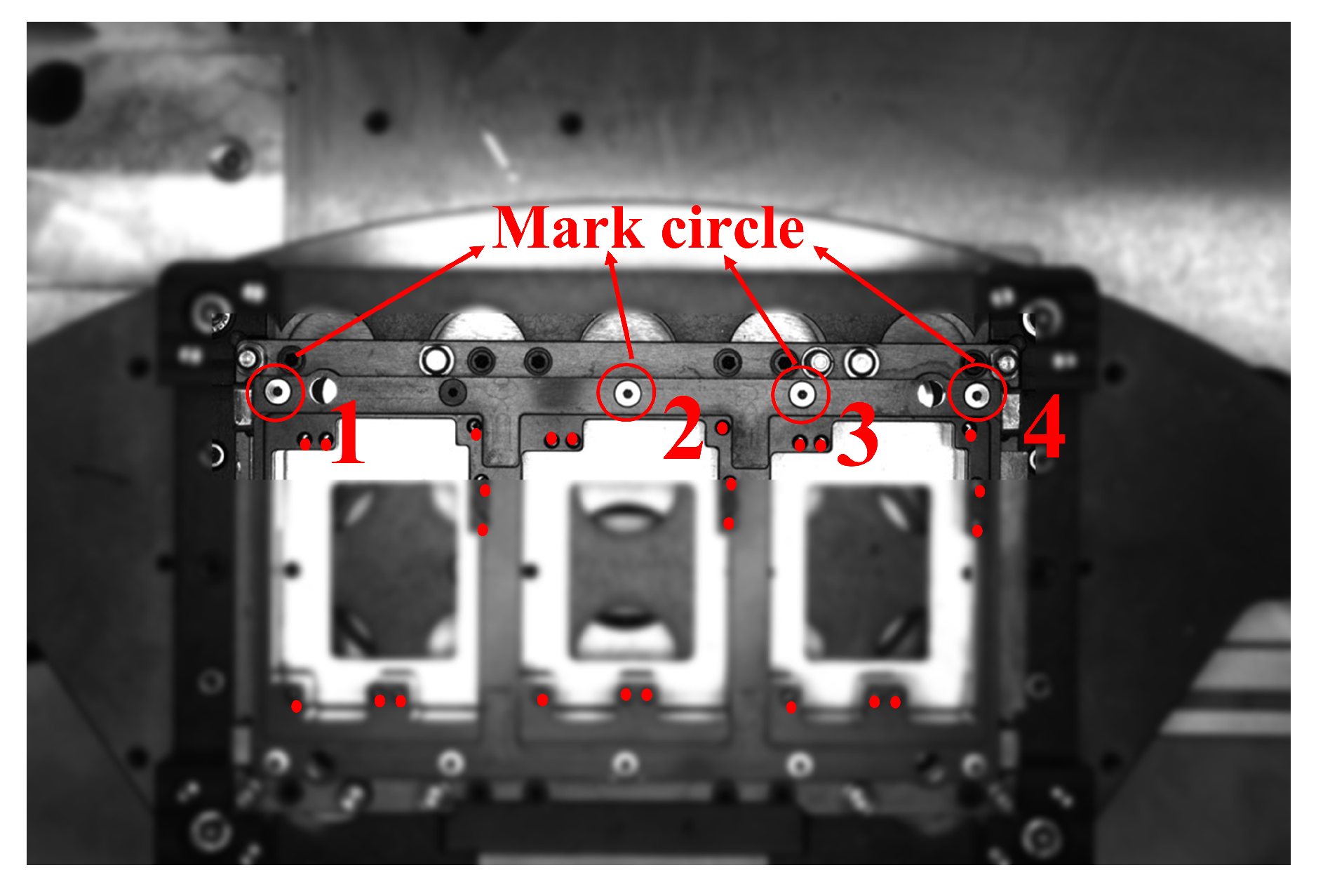
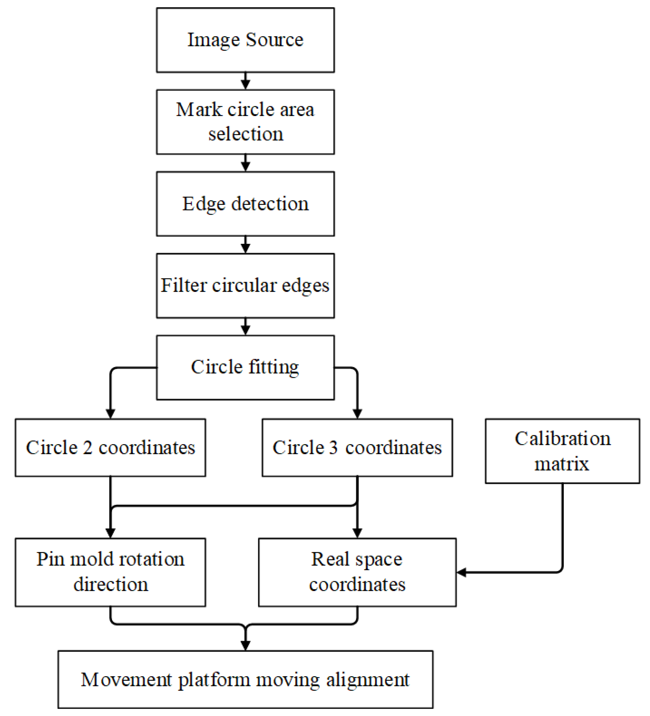
4.3. Pin Insertion Alignment
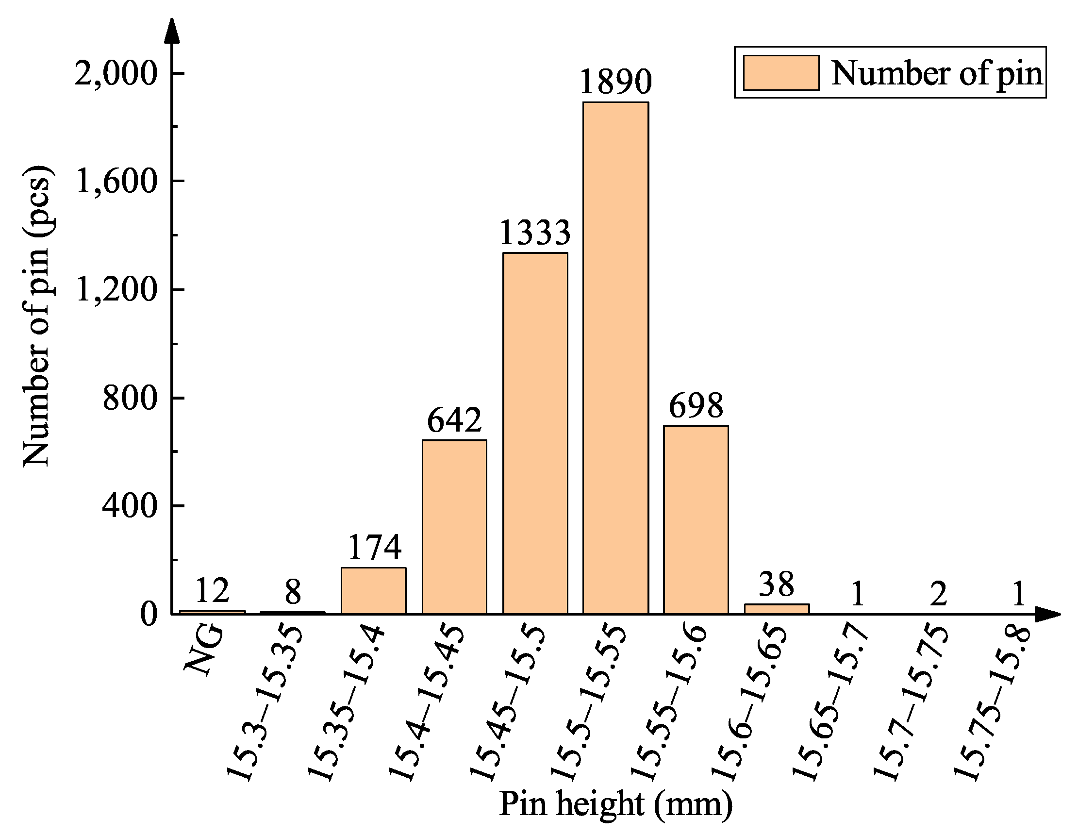
4.4. Pin Height Detection
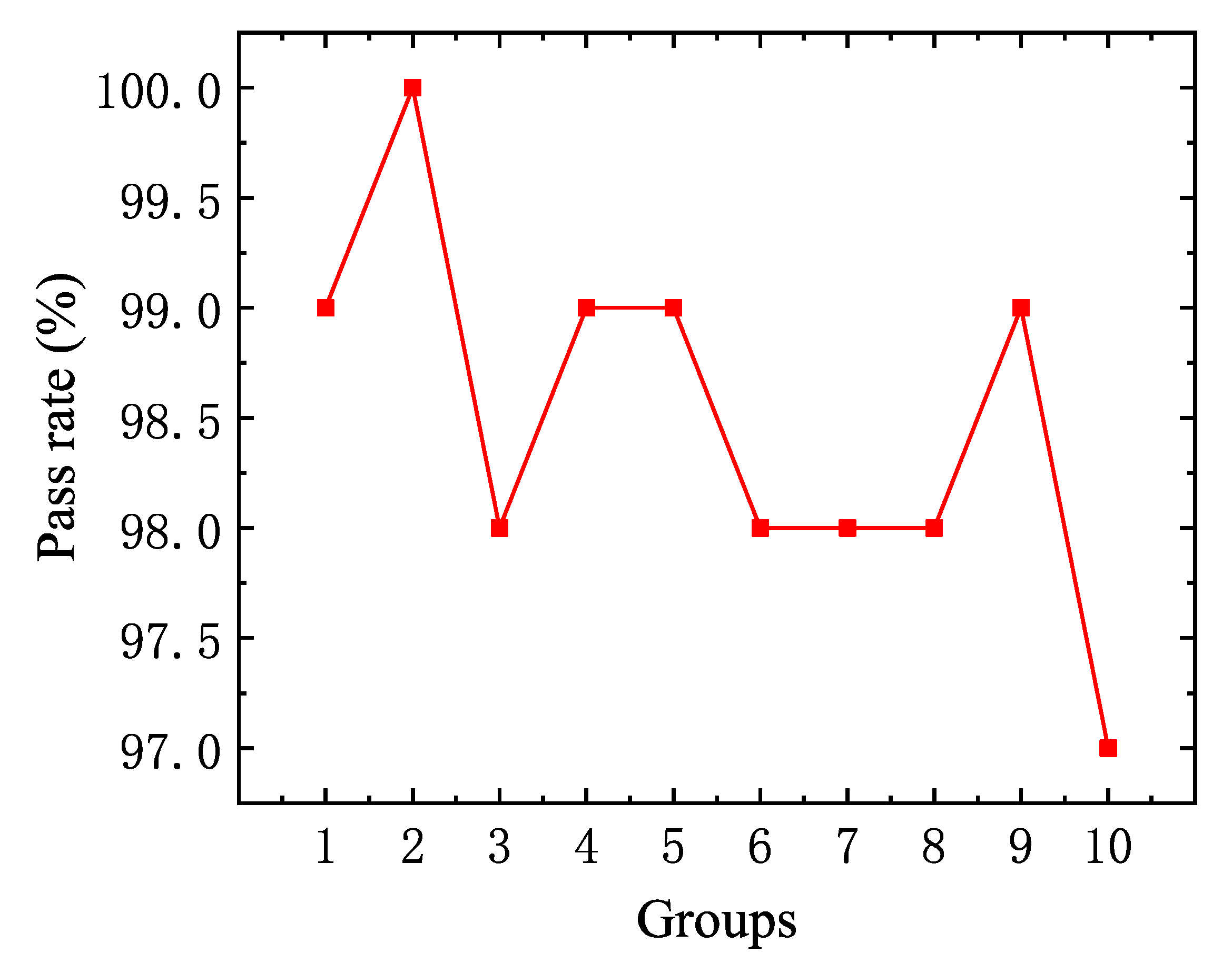
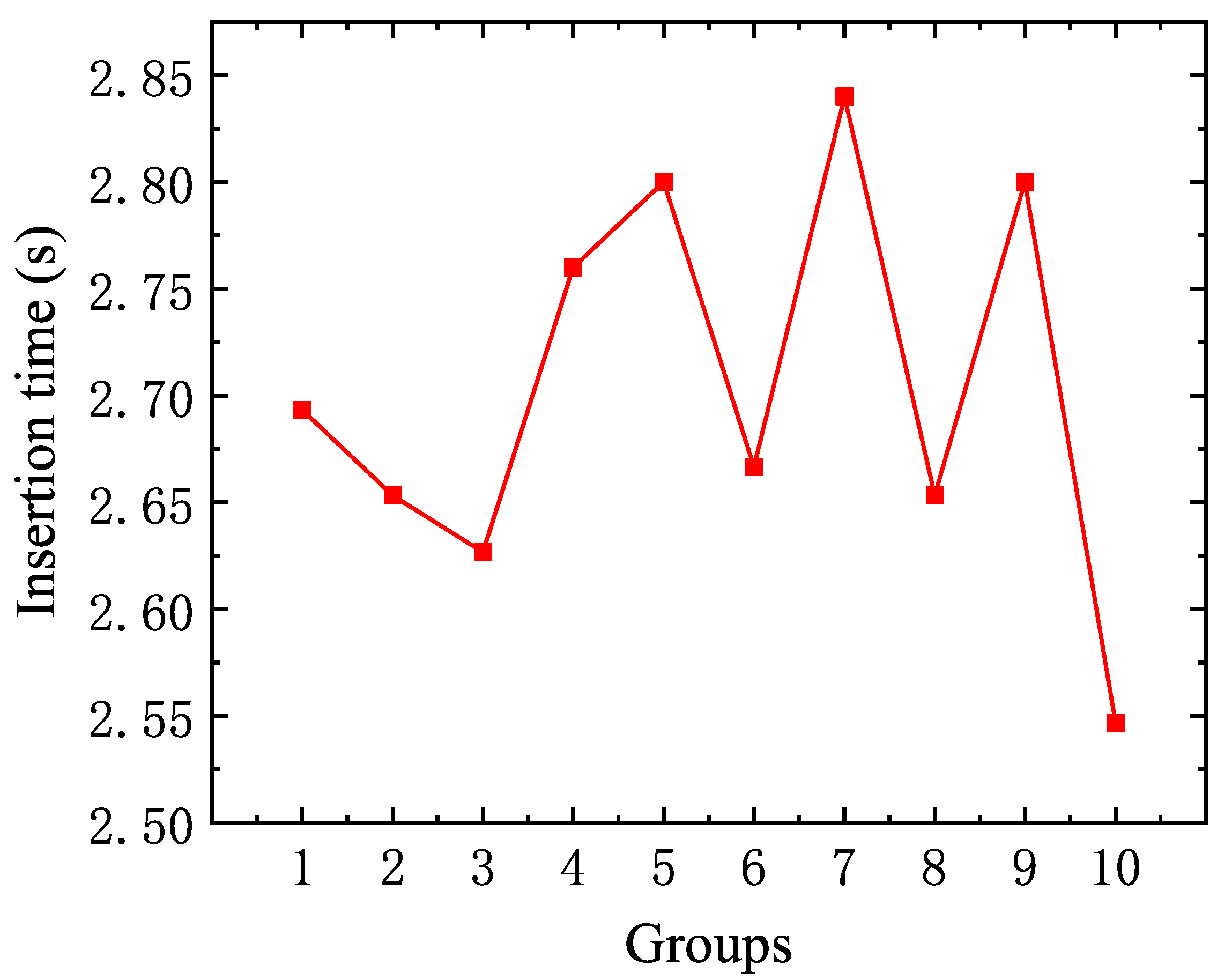
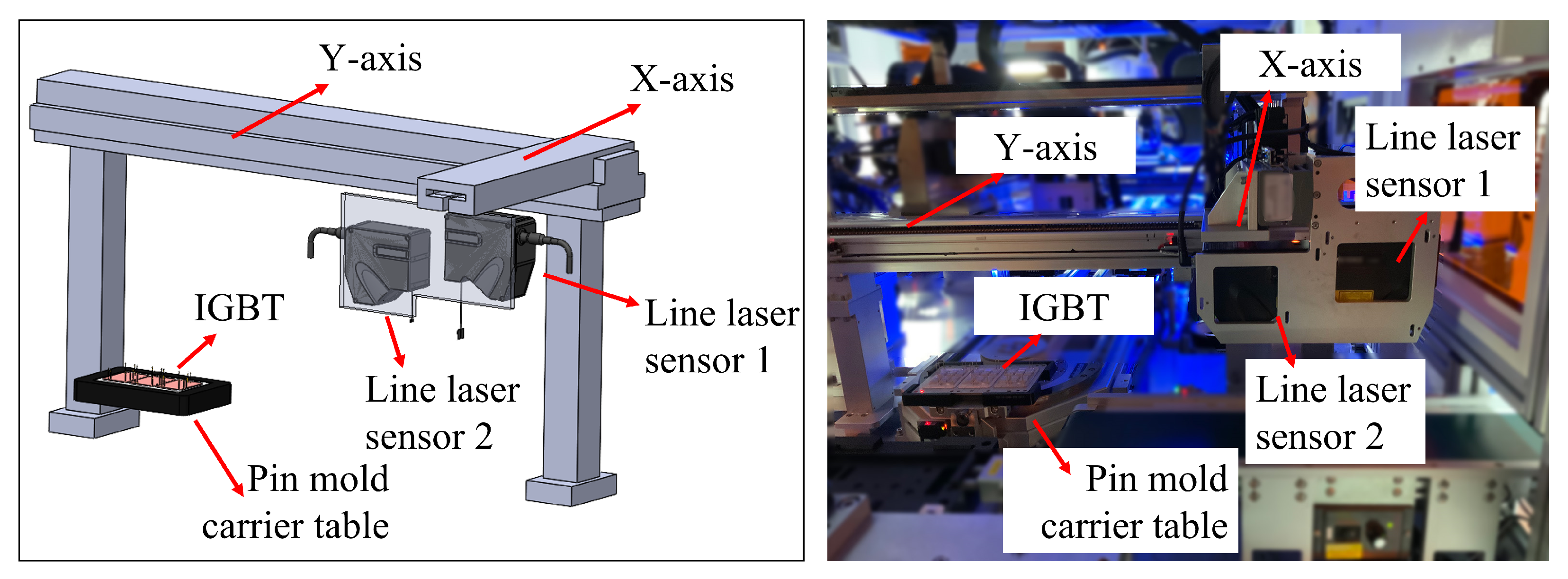
5. Onboard Testing
6. Conclusions
Author Contributions
Funding
Data Availability Statement
Conflicts of Interest
References
- Zhang, Z.; Liu, Y.; Wang, J. Optimal Design of Multi-channel Water Cooled Radiator for Motor Controller of New Energy Vehicle. CES Trans. Electr. Mach. Syst. 2022, 6, 87–94. [Google Scholar] [CrossRef]
- Gu, W.; Zhang, X.; Zhang, B.; Lin, Q.; Jia, Z.; Liu, F.; Qiu, J.; He, Y.; Li, Q. Experimental and numerical investigation on turbulent convection enhancement in minichannel heat sink with staggered V-shaped pin fins. Numer. Heat Transf. Part Appl. 2024, 1–24. [Google Scholar] [CrossRef]
- Wang, L.; Zhou, M.; Guo, M.; Sha, Y.; Diao, L.; Dongye, Z.; Jiang, X.; Xu, C. A Mapping Method of Solder Layer Fatigue Stress and Remaining Useful Life for IGBT Module in a Traction Converter Based on the Mission-profile. Proc. CSEE 2022, 42, 269–278. [Google Scholar] [CrossRef]
- Min, W.; Ying, W.; Kai, C.; Yuhua, C.; Gen, Q. Fault diagnostic of insulatedgate bipolar transistor: Overview and prospect. J. Electron. Meas. Instrum. 2024, 38, 1–14. [Google Scholar] [CrossRef]
- Sun, W.; Wang, L.; Zhu, N.; Xin, J.; Luo, Y.; Jiang, X.; Fan, G.; Chen, M. Characterization of packaging warpage, residual stress and their effects on the mechanical reliability of IGBT power modules. Eng. Fail. Anal. 2023, 152, 107517. [Google Scholar] [CrossRef]
- Yongle, H.; Yifei, L.; Fei, X.; Binli, L.; Xin, T. Physics of failure of die-attach joints in IGBTs under accelerated aging: Evolution of micro-defects in lead-free solder alloys. Microelectron. Reliab. 2020, 109, 113637. [Google Scholar] [CrossRef]
- Wang, X.; Tao, Z.; Yang, B.; An, Q. Prediction Method of Fatigue Life of Cylindrical Cam Rollers in Pin Insertion Mechanism. J. Zhengzhou Univ. Eng. Sci. 2023, 44, 41–47. [Google Scholar] [CrossRef]
- Bin, X.; Chang, S.; Huihui, C.; Qingsen, M.; Shuanben, J. Method of Electronic Component Location, Grasping and Inserting Based on Machine Vision. In Proceedings of the 2020 International Wireless Communications and Mobile Computing (IWCMC), Limassol, Cyprus, 15–19 June 2020; pp. 1968–1971. [Google Scholar] [CrossRef]
- He, J.; Jiang, L.; Zhang, S.; Li, R.; Xu, C.; Liu, X.; Shen, Y. Fast plug-in capacitors polarity detection with morphology and SVM fusion method in automatic optical inspection system. Signal Image Video Process. 2023, 17, 2555–2563. [Google Scholar] [CrossRef]
- Lin, X.; Xu, G.; Wei, W. Online Detection of IGBT Voltage Rise Time Based on RC Circuit Current. IEEE Trans. Instrum. Meas. 2025, 74, 9005713. [Google Scholar] [CrossRef]
- Cheng, S.; Liu, C.; Yuan, W.; Xiang, C.; Hu, Y.; Xie, W.; Wang, W. Research on IGBT Chip Bond Wire Lift-Off Fault Detection Method Based on Decoupling of Time Domain Reflective Signal Feature. IEEE Trans. Power Electron. 2025, 40, 6055–6068. [Google Scholar] [CrossRef]
- Geng, X.; He, Y.; Tang, L.; Chang, S.; Zhang, J.; Yang, W.; Yuan, M.; Wang, G.; Li, Q.; Ping, Y.; et al. Investigation of the Effect of Bonding Wires Degradation on Switching Stress Waves Released During Power Cycling in Discrete IGBT. IEEE J. Emerg. Sel. Top. Power Electron. 2025, 13, 2057–2069. [Google Scholar] [CrossRef]
- Shen, X.; Zhang, X.; Shen, H.; Dongye, Z.; Gu, B.; Qi, L. Identification of IGBT Bonding Wire Degradation Based on Feature Extraction and State Classification. IEEE Trans. Power Electron. 2025, 1–9. [Google Scholar] [CrossRef]
- Jiayu, L. Research on Technologies of Pin’s Detection for Avionics Electronic Connector Based on Machine Vision. Ph.D. Thesis, Harbin Institute of Technology, Harbin, China, 2017. [Google Scholar] [CrossRef]
- Zhao, W.; Pan, S.; Li, Z. Design of connector PIN needle skew detection system based on machine vision. J. Guangxi Univ. Sci. Technol. 2023, 34, 100–107. [Google Scholar] [CrossRef]
- Edwards, C.; Vaske, A.; McDaniel, N.; Pradhan, D.; Panda, D. Real-Time Change Detection for Automated Test Socket Inspection Using Advanced Computer Vision and Machine Learning. IEEE Trans. Semicond. Manuf. 2023, 36, 332–339. [Google Scholar] [CrossRef]
- Zanqin, W. Research on Detection Technology of Aerospace Electrical Connector Pins and Excess Objects. Master’s Thesis, Harbin Institute of Technology, Harbin, China, 2024. [Google Scholar]
- Polverini, M.; Zanchettin, A.M.; Castello, S.; Rocco, P. Sensorless and constraint based peg-in-hole task execution with a dual-arm robot. In Proceedings of the 2016 IEEE International Conference on Robotics and Automation (ICRA), Stockholm, Sweden, 16–21 May 2016; pp. 415–420. [Google Scholar] [CrossRef]
- Lin, H.I. Development of an intelligent transformer insertion system using a robot arm. Robot. Comput.-Integr. Manuf. 2018, 51, 209–221. [Google Scholar] [CrossRef]
- Aginaga, J.; Iriarte, X.; Plaza, A.; Mata, V. Kinematic Design of a New Four Degree-of-Freedom Parallel Robot for Knee Rehabilitation. J. Mech. Des. 2018, 140, 092304. [Google Scholar] [CrossRef]
- Bartyzel, G.; Półchłopek, W.; Rzepka, D. Reinforcement Learning With Stereo-View Observation for Robust Electronic Component Robotic Insertion. J. Intell. Robot. Syst. 2023, 109, 57. [Google Scholar] [CrossRef]
- Chang, Z.; Xu, C.; Pan, T.; Wang, L.; Zhang, X. A general framework for geometry design of indexing cam mechanism. Mech. Mach. Theory 2009, 44, 2079–2084. [Google Scholar] [CrossRef]
- Lederer, H.; Lonij, G.; Corves, B. Application of higher order derivatives in the synthesis of crank and cam mechanisms. In Computational Kinematics; Springer: Berlin/Heidelberg, Germany, 2009; pp. 217–224. ISBN 978-3-642-01946-3. [Google Scholar]
- Nguyen, T.; Kurtenbach, S.; Hüsing, M.; Corves, B. A general framework for motion design of the follower in cam mechanisms by using non-uniform rational B-spline. Mech. Mach. Theory 2019, 137, 374–385. [Google Scholar] [CrossRef]
- Zhou, C.; Hu, B.; Chen, S.; Ma, L. Design and analysis of high-speed cam mechanism using Fourier series. Mech. Mach. Theory 2016, 104, 118–129. [Google Scholar] [CrossRef]
- Li, G.; Yin, C.; Jiang, D.; Ke, W. Design and analysis of the cylinder cam mechanism of the group cover machine. Food Mach. 2020, 36, 131–135. [Google Scholar]
- Abderazek, H.; Yildiz, A.R.; Mirjalili, S. Comparison of recent optimization algorithms for design optimization of a cam-follower mechanism. Knowl.-Based Syst. 2020, 191, 105237. [Google Scholar] [CrossRef]
- Rao, R.V.; Pawar, R.B. Design optimization of cam–follower mechanisms using Rao algorithms and their variants. Evol. Intell. 2024, 17, 745–770. [Google Scholar] [CrossRef]
- Güven, O.; Karaaslan, B.H.; Çakan, A.; Özer, S. Cylindrical cam mechanism design with visual basic. Eur. Mech. Sci. 2023, 7, 22–28. [Google Scholar] [CrossRef]
- Zhao, Y. Reliability Optimization Design of Mechanical Interface Based on Cylindrical Cam Mechanism. Master’s Thesis, Dalian Maritime University, Dalian, China, 2019. [Google Scholar]
- Minghui, D. Study on the Cam Profile Modification and Optimization of Cylindrical Cam Continuous Transmission Mechanism. Master’s Thesis, Wuhan University of Technology, Wuhan, China, 2016. [Google Scholar]
- Shin, J.H.; Kim, J.S.; Ha, K.H. A Study on the Kinetodynamic Analysis for General Disk Cam Driving Slider Mechanisms. Trans. Korean Soc. Mech. Eng. A 1997, 21, 871–883. [Google Scholar]
- Tengyue, T. An Comprehensive Error Free Design for Oscillating Follower Spatial Cam. Master’s Thesis, Zhejiang University, Hangzhou, China, 2014. [Google Scholar]
- Shi, Y.; Wu, Y. Cam Mechanism Design and Application Innovation; China Machine Press: Beijing, China, 2007. [Google Scholar]
- Liping, Z.; Wang, X.; Li, D.; Sun, L.; Cai, W.; Ning, X. Finger Vein Image Enhancement Based on Guided Tri-Gaussian Filters. ASP Trans. Pattern Recognit. Intell. Syst. 2021, 1, 17–23. [Google Scholar] [CrossRef]
- Tian, W.; Tian, M.; Zhuang, Z.; Zhao, J. Height inspection of IGBT pins based on stereovision. Electron. Packag. 2023, 23, 36–42. [Google Scholar] [CrossRef]
- Yaoxing, K. Research on Automobile Connector Pin Detection System Based on Machine Vision. Master’s Thesis, Yanshan University, Qinhuangdao, China, 2021. [Google Scholar]
- Aixin, C. Study on Effect of Vibration on Insertion Accuracy of High-Speed Insertion Machine. Master’s Thesis, Shanghai Jiaotong University, Shanghai, China, 2010. [Google Scholar]

| Cams | Angular Displacement of Oscillating Parts | Cam Angle | Polynomial Coefficients |
|---|---|---|---|
| Feed cams | |||
| Stabilising cams | |||
| Clamping cam left cutter | |||
| Clamping cam right cutter | |||
| Pin insertion cams |
| Stroke Phase | Seventh-Degree Polynomial Curve Equation | Turning Angle (°) |
|---|---|---|
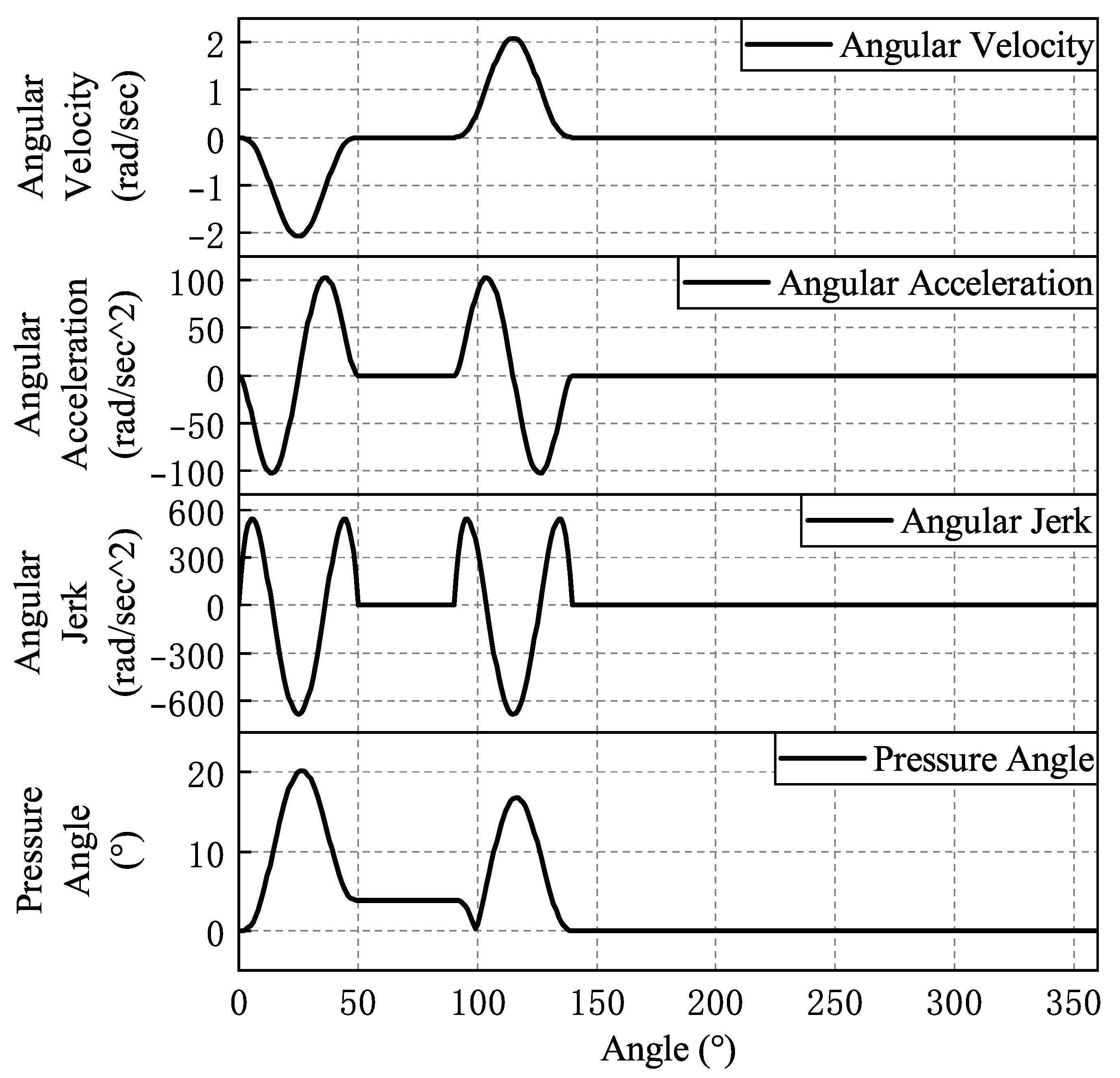
| Lift Stage | [0,50] | |
| Far Rest Stage | [50,90] | |
| Return Stage | [90,140] | |
| Near Rest Phase | [140,360] |
| Stroke Phase | Seventh-Degree Polynomial Curve Equation | Turning Angle (°) |
|---|---|---|
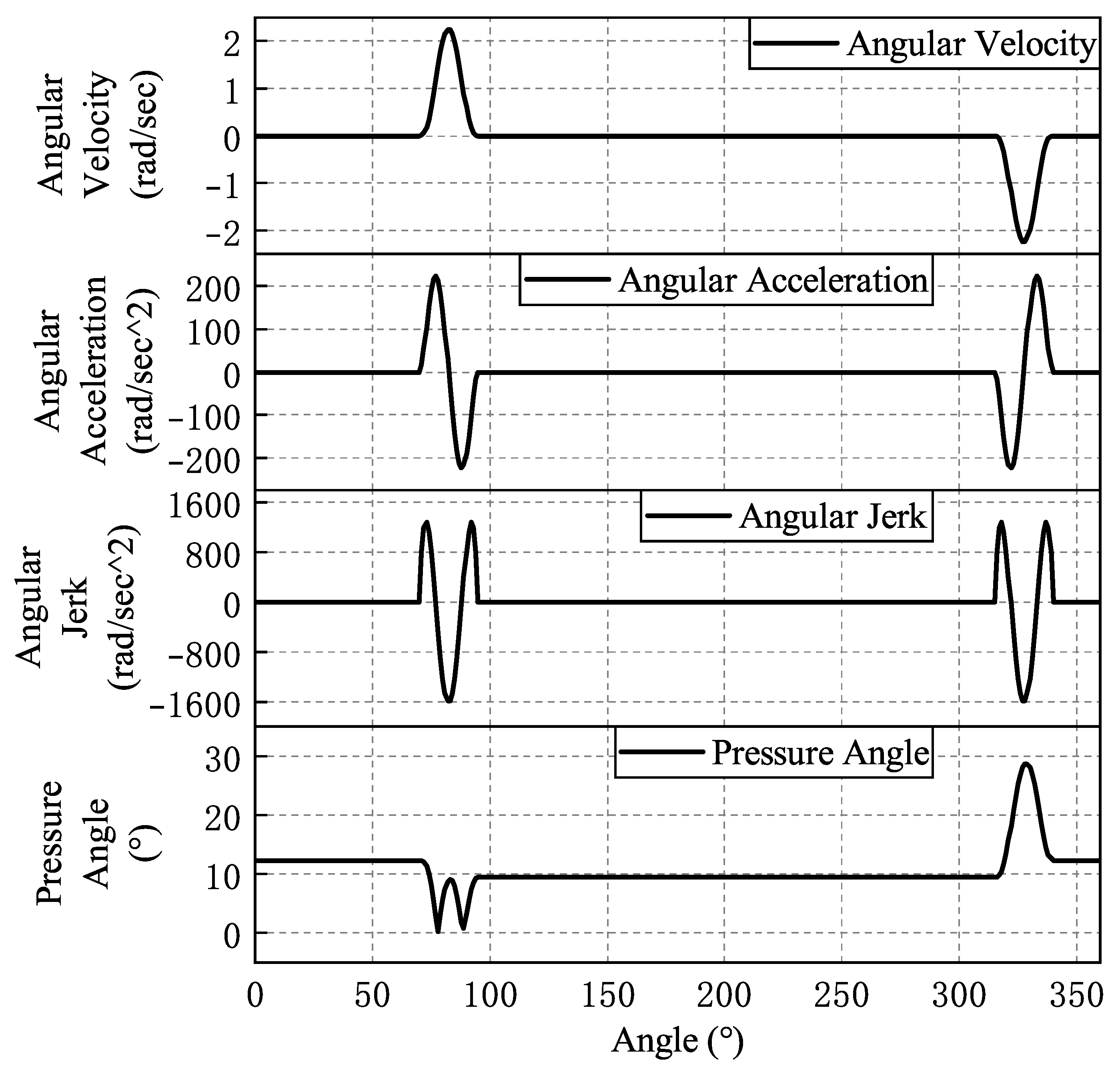
| Near Rest Phase | [0,70] U [340,360] | |
| Lift Stage | [70,95] | |
| Far Rest Stage | [95,315] | |
| Return Stage | [315,340] |
| Stroke Phase | Seventh-Degree Polynomial Curve Equation | Turning Angle (°) |
|---|---|---|
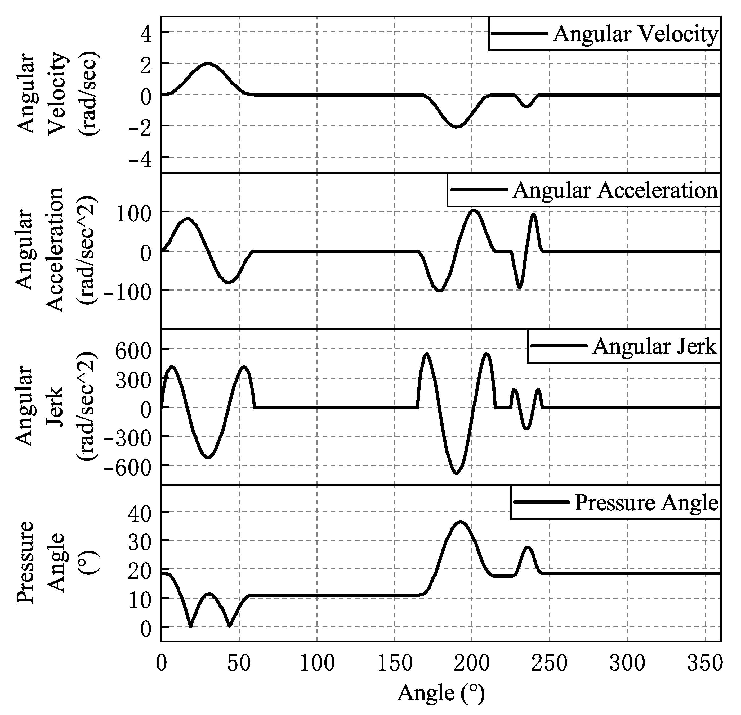
| Lift Stage | [0,60] | |
| Far Rest Stage 1 | [60,165] | |
| Return Stage 1 | [165,215] | |
| Far Rest Stage 2 | [215,225] | |
| Return Stage 2 | [225,245] | |
| Near Rest Phase | [245,360] |
| Stroke Phase | Seventh-Degree Polynomial Curve Equation | Turning Angle (°) |
|---|---|---|
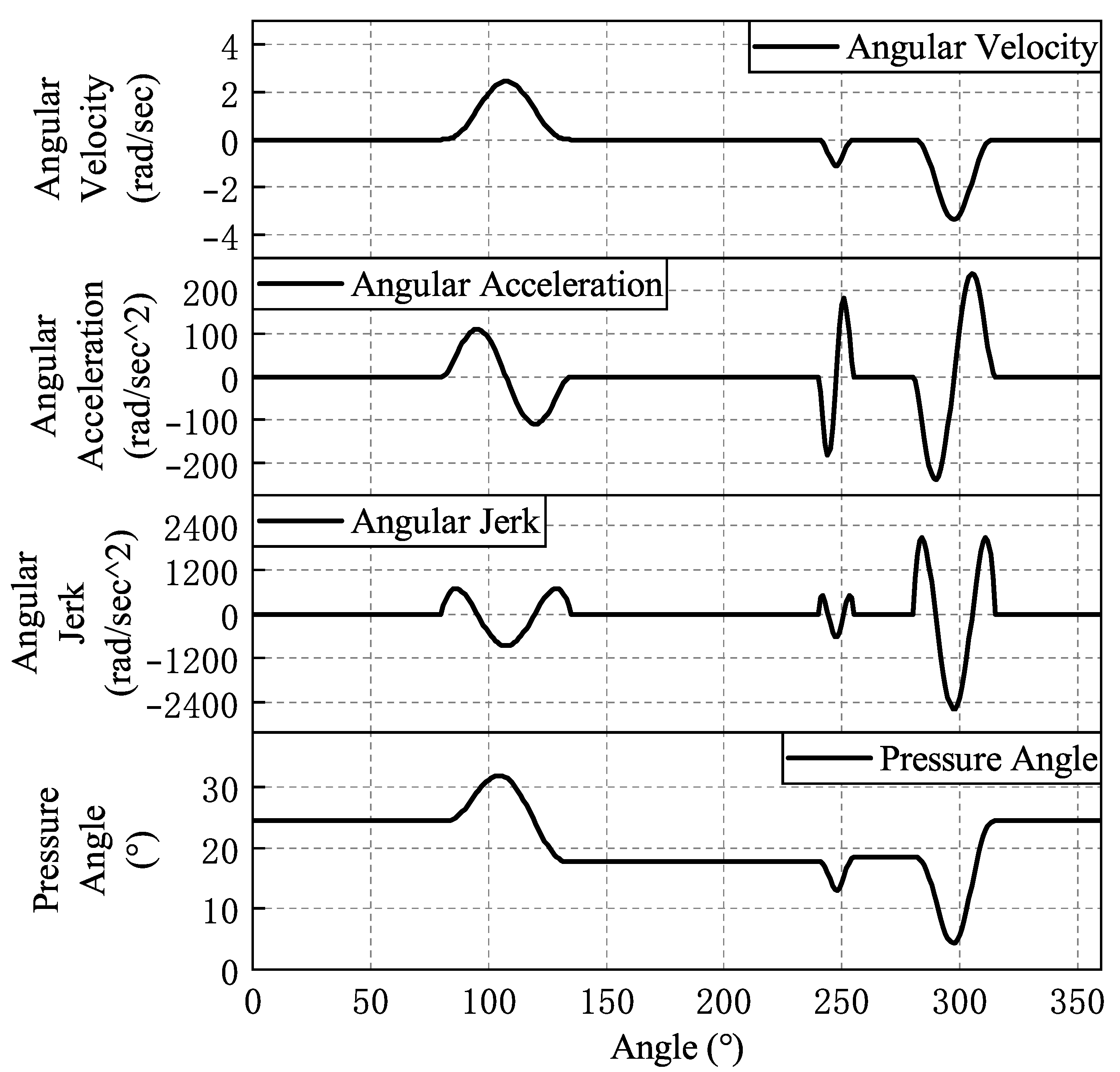
| Near Rest Phase | [0,80] U [315,360] | |
| Lift Stage | [80,135] | |
| Far Rest Stage 1 | [135,240] | |
| Return Stage 1 | [240,255] | |
| Far Rest Stage 2 | [255,280] | |
| Return Stage 2 | [280,315] |
| Stroke Phase | Seventh-Degree Polynomial Curve Equation | Turning Angle (°) |
|---|---|---|
| Far Rest Stage | [0,135] U [285,360] | |
| Lift Stage 1 | [135,145] | |
| Near Rest Phase 1 | [145,150] | |
| Lift Stage 2 | [150,215] | |
| Near Rest Phase 2 | [215,220] | |
| Return Stage | [220,285] |
| Cams | Maximum Angular Velocity (rad/s) | Maximum Angular Acceleration () | Maximum Angular Jerk () | Maximum Pressure Angle (°) |
|---|---|---|---|---|
| Feed cams | 2.1 | 102.9 | 683.9 | 20 |
| Stabilizing cams | 2.2 | 222.5 | 1583.8 | 28.6 |
| Clamping cam left clevis | 2.1 | 102.5 | 679.2 | 36.3 |
| Clamping cam right cutter | 3.4 | 237.9 | 2556.7 | 31.9 |
| Pin insertion cams | 2.5 | 384.1 | 1959.6 | 24.7 |
| Reason for Pin Missing | Number of Pins (pcs) | Number of Pin Molds |
|---|---|---|
| Pin empty welded | 8 | 1 |
| Pin was pulled out | 4 | 4 |
| Height measuring platform leakage | 0 | 0 |
Disclaimer/Publisher’s Note: The statements, opinions and data contained in all publications are solely those of the individual author(s) and contributor(s) and not of MDPI and/or the editor(s). MDPI and/or the editor(s) disclaim responsibility for any injury to people or property resulting from any ideas, methods, instructions or products referred to in the content. |
© 2025 by the authors. Licensee MDPI, Basel, Switzerland. This article is an open access article distributed under the terms and conditions of the Creative Commons Attribution (CC BY) license (https://creativecommons.org/licenses/by/4.0/).
Share and Cite
Tian, W.; Zhang, P.; Tian, M.; Chen, S.; Ji, H.; Ma, B. Cam Design and Pin Defect Detection of Cam Pin Insertion Machine in IGBT Packaging. Micromachines 2025, 16, 829. https://doi.org/10.3390/mi16070829
Tian W, Zhang P, Tian M, Chen S, Ji H, Ma B. Cam Design and Pin Defect Detection of Cam Pin Insertion Machine in IGBT Packaging. Micromachines. 2025; 16(7):829. https://doi.org/10.3390/mi16070829
Chicago/Turabian StyleTian, Wenchao, Pengchao Zhang, Mingfang Tian, Si Chen, Haoyue Ji, and Bingxu Ma. 2025. "Cam Design and Pin Defect Detection of Cam Pin Insertion Machine in IGBT Packaging" Micromachines 16, no. 7: 829. https://doi.org/10.3390/mi16070829
APA StyleTian, W., Zhang, P., Tian, M., Chen, S., Ji, H., & Ma, B. (2025). Cam Design and Pin Defect Detection of Cam Pin Insertion Machine in IGBT Packaging. Micromachines, 16(7), 829. https://doi.org/10.3390/mi16070829