
Design and Electromagnetic Performance Optimization of a MEMS Miniature Outer-Rotor Permanent Magnet Motor


Abstract
1. Introduction
2. Design
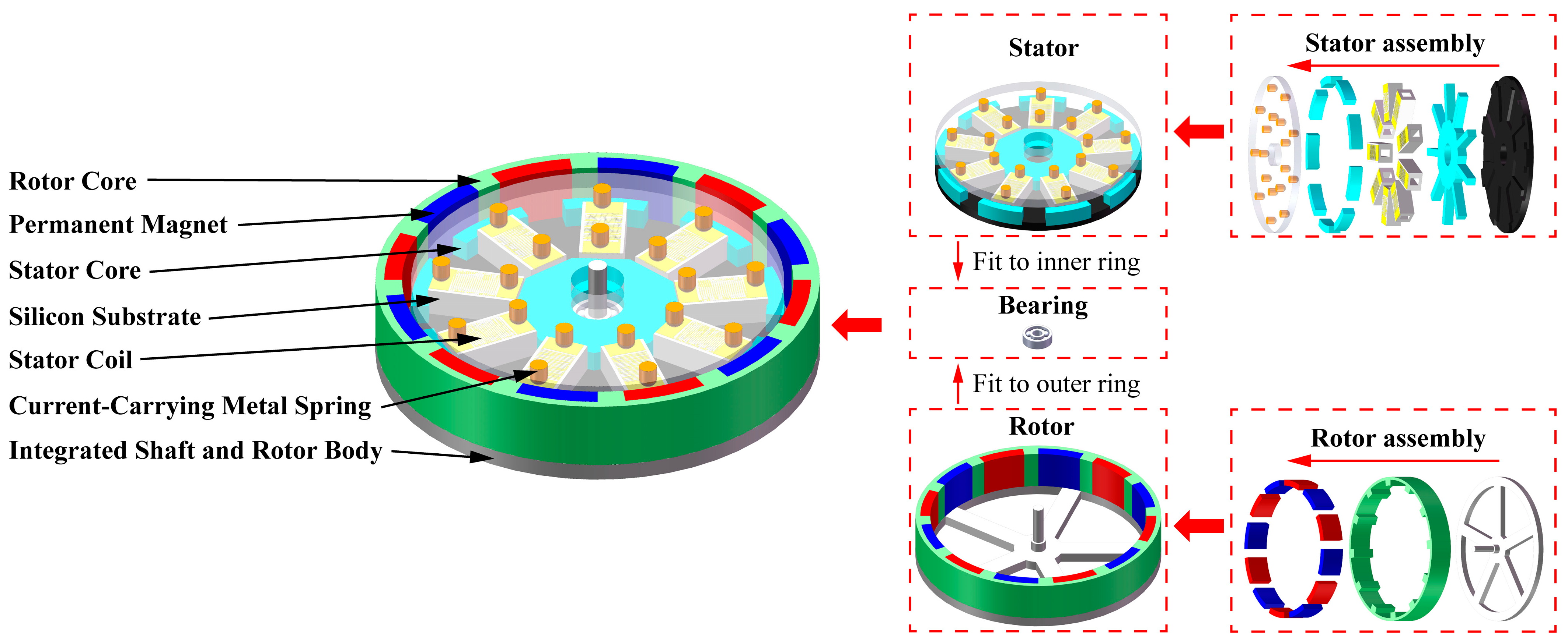
2.1. Model Design
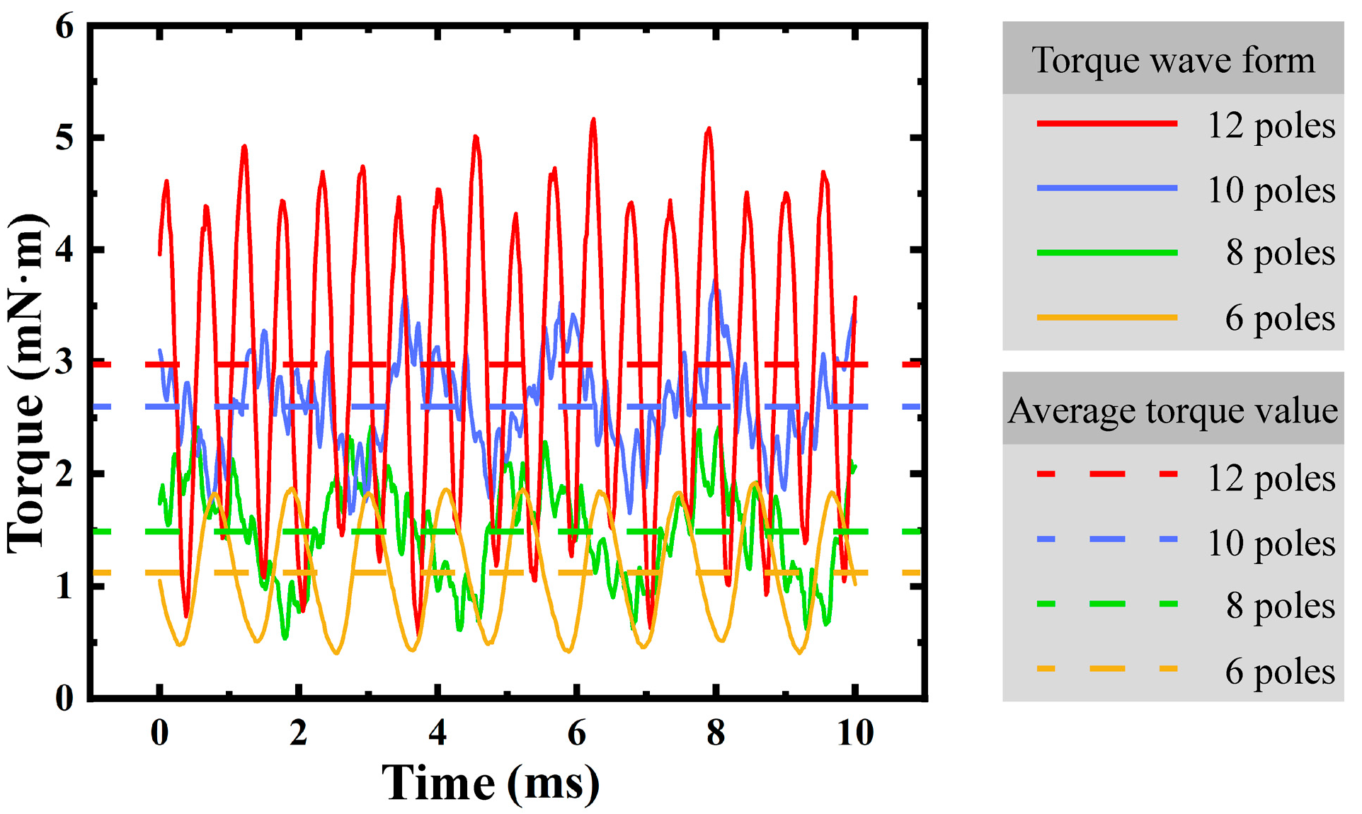
2.2. Pole Number Design
2.3. Fundamental Parameters
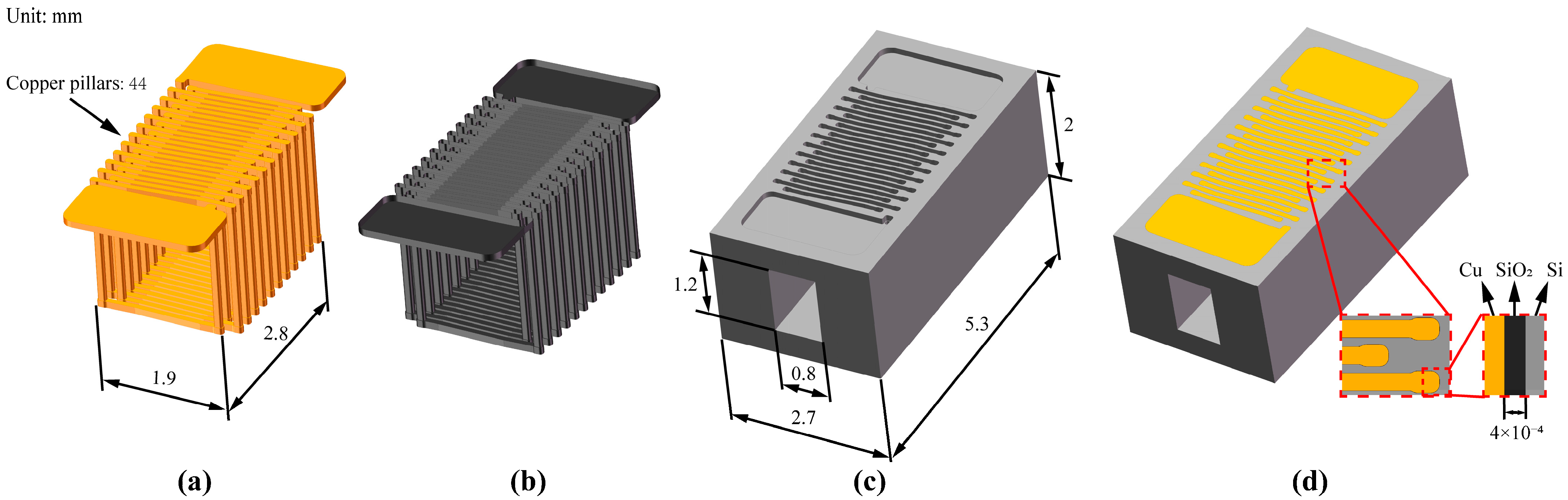
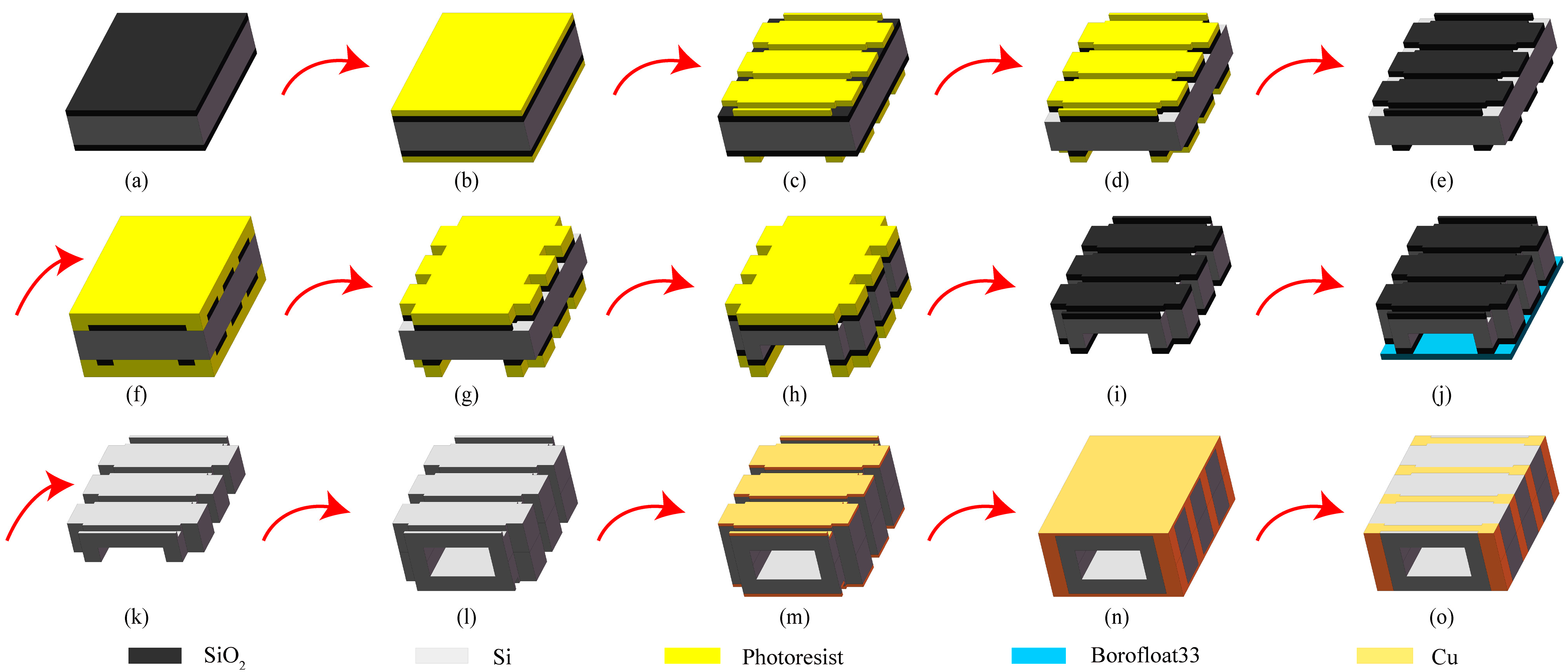
2.4. Manufacturing Method Design
- (a)
- Prepare two pieces of intrinsic silicon wafers with double-side oxidation, ensuring that they meet the process requirements, with a thickness of 1 mm and an oxide layer thickness of 2 μm.
- (b)
- Apply a thin photoresist on both sides of the silicon wafer. First, perform pre-baking, and then apply the photoresist. The spin-coating speed and time parameters are 4000 rpm for 50 s. After that, put it into an oven and bake at 115 °C for 30 min to dry it for subsequent exposure.
- (c)
- Expose the pattern on both sides once. First, cool the silicon wafer to room temperature, and expose different patterns on the upper and lower surfaces, respectively, with an exposure time of 3 s, and then perform the development operation.
- (d)
- Double-sided BOE (Buffered Oxide Etch). Soak the exposed silicon wafer in a BOE solution (mainly composed of components such as hydrofluoric acid (HF) and ammonium fluoride (NH4F)). Remove the exposed oxide layer. Observe under a microscope. When colored stripes appear, try to remove them until the oxide layer is completely removed.
- (e)
- Remove the thin photoresist on both sides. Use a piranha solution (concentrated sulfuric acid (H2SO4) and hydrogen peroxide (H2O2) in a ratio of 3:1) to wash off the photoresist, then rinse it thoroughly with deionized water, and finally dry it with a spin dryer.
- (f)
- Apply a thick photoresist on both sides of the silicon wafer. The spin-coating speed and time parameters are 3000 rpm for 50 s. Control the flow rate and position of the photoresist during spin-coating to ensure a uniform photoresist layer. After that, put it into an oven and bake at 95 °C for 60 min.
- (g)
- Double-sided alignment exposure of the secondary pattern. First, cool the silicon wafer to room temperature, and expose different patterns on the upper and lower surfaces, respectively, with an exposure time of 13 s. Ensure accurate alignment of the patterns, and then perform the development operation.
- (h)
- Double-sided etching. First, perform shallow etching of the alignment marks, and then perform deep etching after covering. Control the time and conduct intermittent depth measurements. Adjust the etching parameters according to the situation during the etching process to ensure the etching depth and shape. Complete the etching of the coil holes and the deep grooves for inserting the iron core.
- (i)
- Remove the thick photoresist on both sides, ensuring that there is no residue on the surface of the silicon wafer.
- (j)
- Attach the substrate to the lower surface and etch the upper surface, with an etching depth of 100 μm, to complete the etching of the coil grooves.
- (k)
- Clean the silicon wafer with HF to remove the oxide layer. Use an HF solution to clean the silicon wafer and remove the surface oxide layer, and then rinse it thoroughly with deionized water to ensure that the oxide layer is completely removed, so as to prepare for the subsequent process.
- (l)
- Double-layer silicon-silicon bonding, ensuring tight bonding without bubbles and voids, to form an integral structure.
- (m)
- Double-sided magnetron sputtering. Perform magnetron sputtering operations on both sides of the silicon wafer and sequentially deposit metallic titanium and metallic copper. Control the sputtering parameters to ensure uniform thin-film thickness and no warping in subsequent tests.
- (n)
- Electroplating. Perform an electroplating operation on the surface of the silicon wafer to deposit the required electroplating layer. Ensure that the electroplating layer has a uniform thickness, good adhesion, and is dense without holes.
- (o)
- Grinding. Perform a grinding operation on the silicon wafer to remove the excess electroplated metal, so that each turn of the coil is separated from the other. At the same time, ensure the flatness of the surface, facilitating subsequent operations such as inputting current. So far, all the MEMS processes for the ultra-miniature 3D coils embedded in silicon are completed.
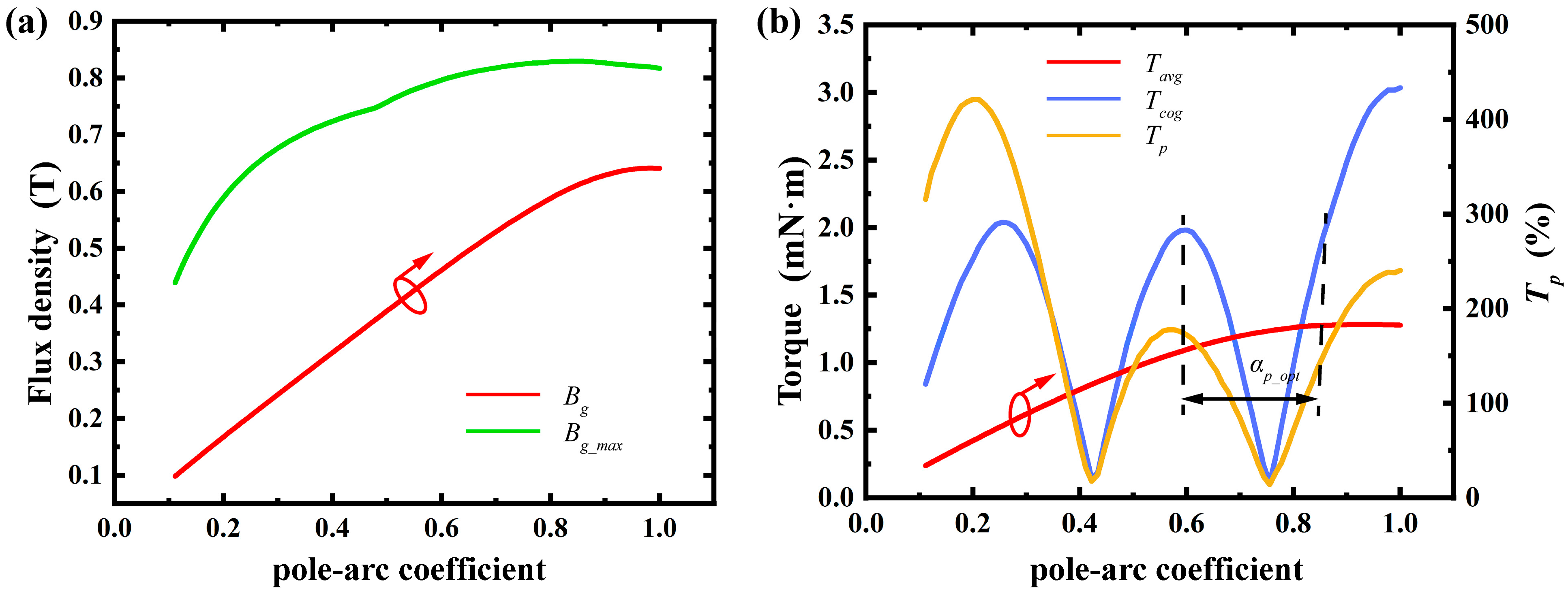
2.5. Magnetic Density Design
3. Method
- The external boundary was set to an air domain that fully encapsulates the motor.
- The rotor was defined as the rotating component with an initial phase angle of 0°.
- The rotational speed was set to the standard speed of 3000 rpm.
- The excitation source was defined as a sinusoidal current drive with an effective value of 0.5 A.
- The winding connection method was set to a star connection.
- The load type was assumed to be a constant torque load.
- Assembly errors were not considered, and a uniform air gap was assumed.
- The material properties of the stator and rotor (such as silicon steel sheets of M350–50A and permanent magnets of N30UH) were set to the standard parameters in the software’s built-in material library.
- Radial Thickness of Permanent Magnet:
- 2.
- Stator Slot Shoulder Height:
- 3.
- Air Gap Length:
- 4.
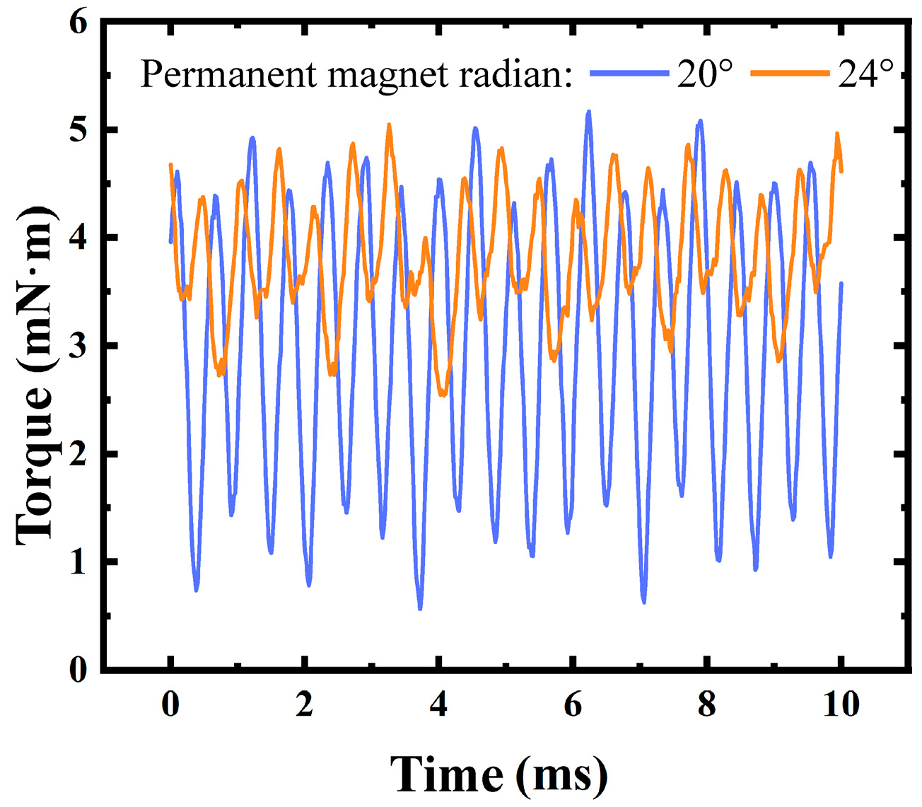
- Arc Length of Permanent Magnet:
- 5.
- Slot Opening Arc Length:
- 6.
- Thickness of Rotor Core Hub:
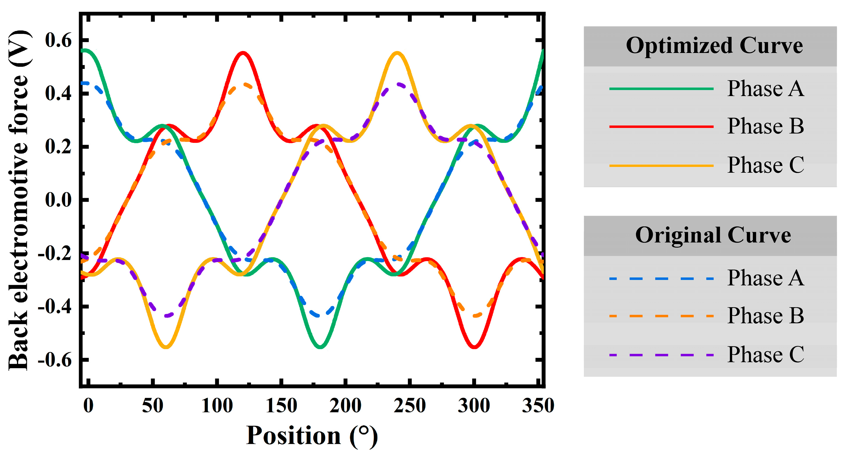
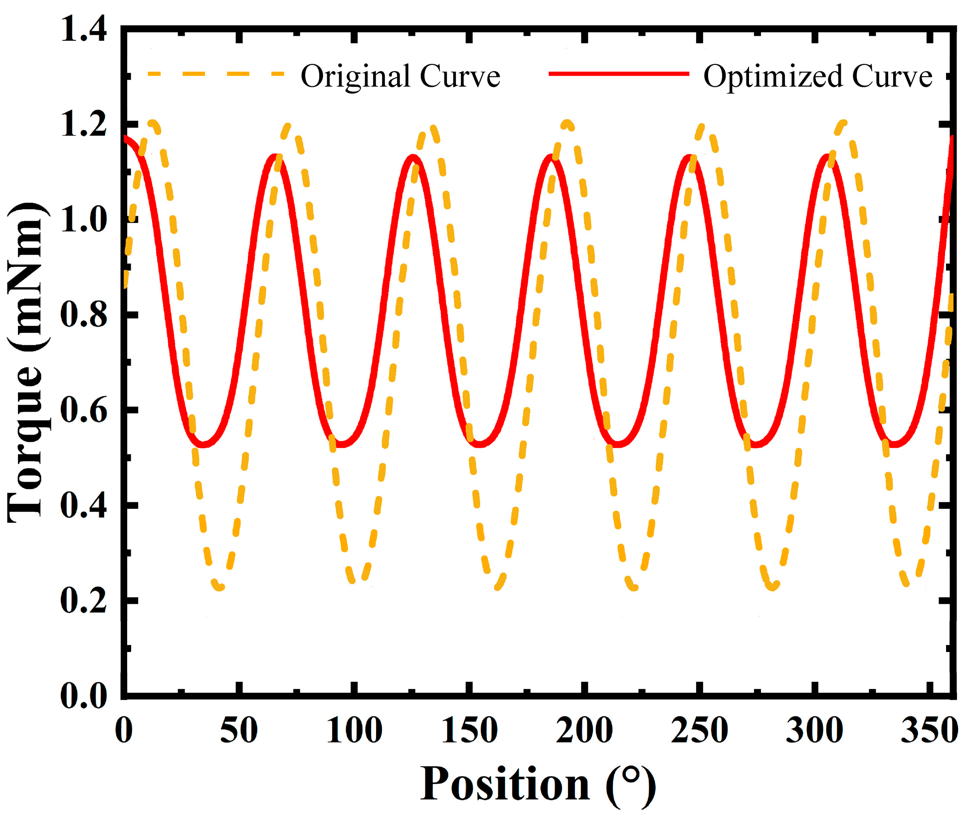
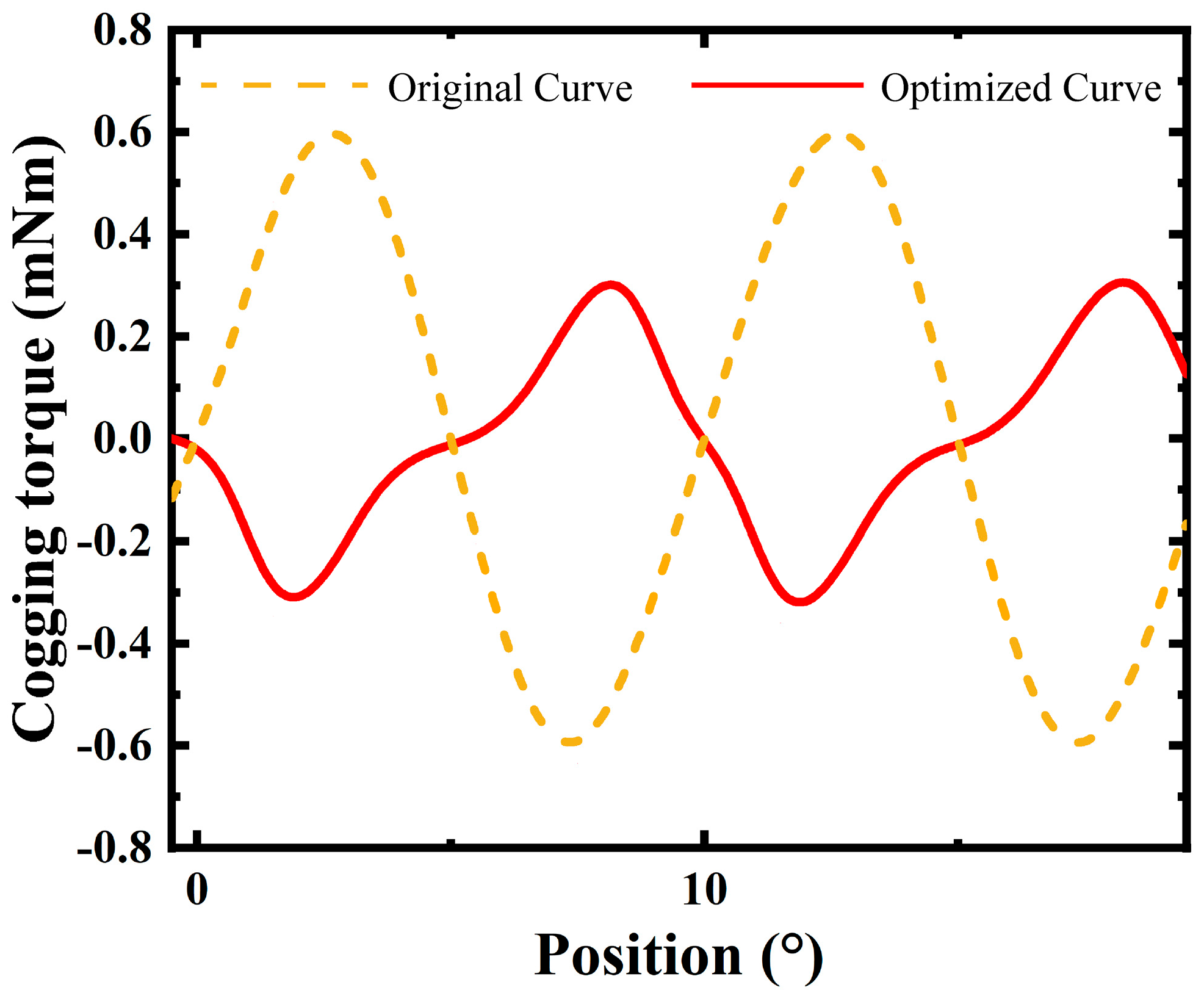
4. Results
5. Conclusions
Author Contributions
Funding
Data Availability Statement
Conflicts of Interest
References
- Qu, H. CMOS MEMS Fabrication Technologies and Devices. Micromachines 2016, 7, 14. [Google Scholar] [CrossRef] [PubMed]
- Fischer, A.C.; Forsberg, F.; Lapisa, M.; Bleiker, S.J.; Stemme, G.; Roxhed, N.; Niklaus, F. Integrating MEMS and ICs. Microsyst. Nanoeng. 2015, 1, 15005. [Google Scholar] [CrossRef]
- Zhu, J.; Liu, X.; Shi, Q.; He, T.; Sun, Z.; Guo, X.; Liu, W.; Sulaiman, O.B.; Dong, B.; Lee, C. Development Trends and Perspectives of Future Sensors and MEMS/NEMS. Micromachines 2020, 11, 7. [Google Scholar] [CrossRef] [PubMed]
- Wang, D.; Watkins, C.; Xie, H. MEMS Mirrors for LiDAR: A Review. Micromachines 2020, 11, 456. [Google Scholar] [CrossRef] [PubMed]
- Rauf, A.M.; Kilberg, B.G.; Schindler, C.B.; Park, S.A.; Pister, K.S.J. Towards aerodynamic control of miniature rockets with MEMS control surfaces. In Proceedings of the 2020 IEEE 33rd International Conference on Micro Electro Mechanical Systems (MEMS), Vancouver, BC, Canada, 18–22 January 2020. [Google Scholar] [CrossRef]
- Smith, G.L.; Rudy, R.Q.; Polcawich, R.G.; DeVoe, D.L. Integrated thin-film piezoelectric traveling wave ultrasonic motors. Sens. Actuators A Phys. 2012, 188, 305–311. [Google Scholar] [CrossRef]
- Yang, B.; Ma, X. Cooling high-speed chips using intelligent control technology. In Proceedings of the 2009 IEEE International Conference on Automation and Logistics, Shenyang, China, 5–7 August 2009; pp. 1330–1334. [Google Scholar] [CrossRef]
- Xie, J.; Zhou, T.; Chen, Y.; Zhou, Y.; Jiang, B.; Zhang, J.; Wang, Z.; Li, W.; Sun, H.; Zhu, X.; et al. A MEMS traveling-wave micromotor-based miniature gyrocompass. Microsyst. Nanoeng. 2025, 11, 27. [Google Scholar] [CrossRef] [PubMed]
- Lyu, S.; Tamaki, Y.; Morishita, K.; Saito, K. Development of rotary-type electrostatic motor for MEMS microrobot. Artif Life Robot. 2025, 30, 148–155. [Google Scholar] [CrossRef]
- Lyu, S.; Tominaga, Y.; Tamaki, Y.; Kiya, D.; Morishita, K.; Saito, K. A study on driving experiments for leg of insect-type microrobot using rotary-type electrostatic motor. In Proceedings of the 2024 IEEE 19th International Conference on Nano/Micro Engineered and Molecular Systems (NEMS), Kyoto, Japan, 2–5 May 2024. [Google Scholar] [CrossRef]
- Yang, T.; Chen, Y.; Li, X.; Zhang, K.; He, J.; Su, W. A low-power piezoelectric MEMS motor using standing wave. Sens. Actuators A Phys. 2025, 387, 116367. [Google Scholar] [CrossRef]
- Ding, X.; Liu, G.; Du, M.; Guo, H.; Qian, H.; Gerada, C. Development of an Axial Flux MEMS BLDC Micromotor with Increased Efficiency and Power Density. Energies 2015, 8, 6608–6626. [Google Scholar] [CrossRef]
- Ding, X.; Liu, G.; Guo, H.; Zhang, C. Accurate Prediction of Leakage Flux Boundaries for an Axial-Flux MEMS Micromotor Design. IEEE Trans. Appl. Supercond. 2016, 26, 612705. [Google Scholar] [CrossRef]
- Ding, X.; Liu, G.; Zuo, Z.; Guo, H. Improved differential-evolution based optimization design of an axial flux MEMS micromotor. Int. J. Appl. Electromagn. Mech. 2017, 53, 645–661. [Google Scholar] [CrossRef]
- Stranczl, M.; Sarajlic, E.; Fujita, H.; Gijs, M.A.M.; Yamahata, C. High-Angular-Range Electrostatic Rotary Stepper Micromotors Fabricated With SOI Technology. J. Microelectromechanical Syst. 2012, 21, 605–620. [Google Scholar] [CrossRef]
- Sarajlic, E.; Yamahata, C.; Cordero, M.; Fujita, H. Three-Phase Electrostatic Rotary Stepper Micromotor With a Flexural Pivot Bearing. J. Microelectromechanical Syst. 2010, 19, 338–349. [Google Scholar] [CrossRef]
- He, J.; Feng, Q.; Chen, Y.; Yang, T.; Li, X.; Zhou, W. High-Resolution Rotation-Measuring System for MEMS Ultrasonic Motors Using Tunneling Magnetoresistance Sensors. Micromachines 2024, 15, 1028. [Google Scholar] [CrossRef] [PubMed]
- Yang, T.; Chen, Y.; Zhang, B.; Cao, B.; Li, X.; Zhang, K.; He, J.; Su, W. A PZT Thin-Film Traveling-Wave Micro-Motor With Stator Teeth Based on MEMS Technology. J. Microelectromech. Syst. 2024, 33, 236–247. [Google Scholar] [CrossRef]
- Büttgenbach, S. Electromagnetic Micromotors—Design. Fabr. Appl. Micromachines 2014, 5, 929–942. [Google Scholar] [CrossRef]
- Achotte, N.; Gilles, P.-A.; Cugat, O.; Delamare, J.; Gaud, P.; Dieppedale, C. Planar brushless magnetic micromotors. J. Microelectromechanical Syst. 2006, 15, 1001–1014. [Google Scholar] [CrossRef]
- Merzaghi, S.; Koechli, C.; Perriard, Y. Development of a Hybrid MEMS BLDC Micromotor. IEEE Trans. Ind. Appl. 2011, 47, 3–11. [Google Scholar] [CrossRef]
- Takato, M.; Mishima, K.; Han, Y.; Saito, K.; Uchikoba, F. Development of electromagnetic MEMS motor without winding wire and application to microrobot. In Proceedings of the 2016 IEEE International Conference on Advanced Intelligent Mechatronics (AIM), Banff, AB, Canada, 12–15 July 2016; pp. 663–668. [Google Scholar] [CrossRef]
- Liu, X.; Wang, C.; Zheng, A. Operation principle and topology structures of axial flux-switching hybrid excitation synchronous machine. In Proceedings of the 2011 International Conference on Electrical Machines and Systems, Beijing, China, 20–23 August 2011; pp. 1–7. [Google Scholar] [CrossRef]
- Hao, Z.; Ma, Y.; Wang, P.; Luo, G.; Chen, Y. A Review of Axial-Flux Permanent-Magnet Motors: Topological Structures, Design, Optimization and Control Techniques. Machines 2022, 10, 1178. [Google Scholar] [CrossRef]
- Choi, Y.C.; Kim, H.-S.; Lee, J.-H. Optimum Design Criteria for Maximum Torque Density and Minimum Torque Ripple of SynRM According to the Rated Wattage Using Response Surface Methodology. IEEE Trans. Magn. 2008, 44, 4135–4138. [Google Scholar] [CrossRef]
- Jo, S.-T.; Shin, H.-S.; Lee, Y.-G.; Lee, J.-H.; Choi, J.-Y. Optimal Design of a BLDC Motor Considering Three-Dimensional Structures Using the Response Surface Methodology. Energies 2022, 15, 461. [Google Scholar] [CrossRef]
- Moghaddam, H.A.; Vahedi, A.; Ebrahimi, S.H. Design Optimization of Transversely Laminated Synchronous Reluctance Machine for Flywheel Energy Storage System Using Response Surface Methodology. IEEE Trans. Ind. Electron. 2017, 64, 9748–9757. [Google Scholar] [CrossRef]
- Yetgin, A.G.; Durmuş, B. Optimization of slot permeance coefficient with average differential evolution algorithm for maximum torque values by minimizing reactances in induction machines. Ain Shams Eng. J. 2021, 12, 2685–2693. [Google Scholar] [CrossRef]
- Bonthu, S.S.R.; Arafat, A.; Choi, S. Comparisons of Rare-Earth and Rare-Earth-Free External Rotor Permanent Magnet Assisted Synchronous Reluctance Motors. IEEE Trans. Ind. Electron. 2017, 64, 9729–9738. [Google Scholar] [CrossRef]
- Nakata, T.; Sanada, M.; Morimoto, S.; Inoue, Y. Automatic Design of IPMSMs Using a Genetic Algorithm Combined with the Coarse-Mesh FEM for Enlarging the High-Efficiency Operation Area. IEEE Trans. Ind. Electron. 2017, 64, 9721–9728. [Google Scholar] [CrossRef]
- Nakata, T.; Sanada, M.; Morimoto, S.; Inoue, Y. Automatic design of IPMSMs using a GA coupled with the coarse-mesh finite element method. In Proceedings of the 19th International Conference on Electrical Machines and Systems (ICEMS), Chiba, Japan, 13–16 November 2016; pp. 1–6. [Google Scholar]
- Zhou, D.; Lu, L.; Yang, C. Optimization of High Speed Permanent Magnet Synchronous Motor Based on Co-simulation Method. In Proceedings of the 5th Asia Energy and Electrical Engineering Symposium (AEEES), Chengdu, China, 23–26 March 2023. [Google Scholar] [CrossRef]
- Wang, Y.; Yao, L.; Shi, D.; Huang, X.; Shen, J.-X. Particle Swarm Optimization of Electromagnetic Vibration of PMSM Using Surrogate Model. Electr. Power Compon. Syst. 2023, 51, 1963–1977. [Google Scholar] [CrossRef]
- Gao, H.; Liu, Z.; Wang, X.; Li, D.; Zhang, T.; Yu, J.; Wang, J. A Novel Motor Structure with Extended Particle Swarm Optimization for Space Robot Control. Sensors 2023, 23, 4126. [Google Scholar] [CrossRef] [PubMed]
- Hassanalian, M.; Abdelkefi, A. Classifications, applications, and design challenges of drones: A review. Prog. Aerosp. Sci. 2017, 91, 99–131. [Google Scholar] [CrossRef]


| Parameter | Value |
|---|---|
| Number of Pole Pairs | 6 |
| Number of Slots | 9 |
| Armature Diameter | 20 mm |
| Shaft Radius | 0.5 mm |
| Motor Length | 2 mm |
| Copper Pillars of a Silicon Substrate Coil | 44 |
| Input Current Waveform | Sine Wave |
| Input Current Amplitude | 0.5 A |
| Symbol | Meaning |
|---|---|
| lm | Radial thickness of permanent magnet |
| hm | Height of the permanent magnet |
| ly | Stator slot shoulder height |
| g | Air gap length |
| Bg_max | Maximum air gap flux density |
| Bg | Average air gap flux density |
| Bcd | Tooth top flux density |
| Bry | Rotor yoke flux density |
| α1 | Arc length of the permanent magnet |
| α2 | Slot opening arc length |
| lry | Thickness of rotor core hub |
| Tavg | Average torque |
| Tcog | Cogging torque |
| Tp | Torque ripple percentage |
Disclaimer/Publisher’s Note: The statements, opinions and data contained in all publications are solely those of the individual author(s) and contributor(s) and not of MDPI and/or the editor(s). MDPI and/or the editor(s) disclaim responsibility for any injury to people or property resulting from any ideas, methods, instructions or products referred to in the content. |
© 2025 by the authors. Licensee MDPI, Basel, Switzerland. This article is an open access article distributed under the terms and conditions of the Creative Commons Attribution (CC BY) license (https://creativecommons.org/licenses/by/4.0/).
Share and Cite
Lei, K.; Li, H.; Li, S.; Xu, T. Design and Electromagnetic Performance Optimization of a MEMS Miniature Outer-Rotor Permanent Magnet Motor. Micromachines 2025, 16, 815. https://doi.org/10.3390/mi16070815
Lei K, Li H, Li S, Xu T. Design and Electromagnetic Performance Optimization of a MEMS Miniature Outer-Rotor Permanent Magnet Motor. Micromachines. 2025; 16(7):815. https://doi.org/10.3390/mi16070815
Chicago/Turabian StyleLei, Kaibo, Haiwang Li, Shijia Li, and Tiantong Xu. 2025. "Design and Electromagnetic Performance Optimization of a MEMS Miniature Outer-Rotor Permanent Magnet Motor" Micromachines 16, no. 7: 815. https://doi.org/10.3390/mi16070815
APA StyleLei, K., Li, H., Li, S., & Xu, T. (2025). Design and Electromagnetic Performance Optimization of a MEMS Miniature Outer-Rotor Permanent Magnet Motor. Micromachines, 16(7), 815. https://doi.org/10.3390/mi16070815