
Optimal Design for a Novel Compliant XY Platform Integrated with a Hybrid Double Symmetric Amplifier Comprising One-Lever and Scott–Russell Mechanisms Arranged in a Perpendicular Series Layout for Vibration-Assisted CNC Milling


Abstract
1. Introduction
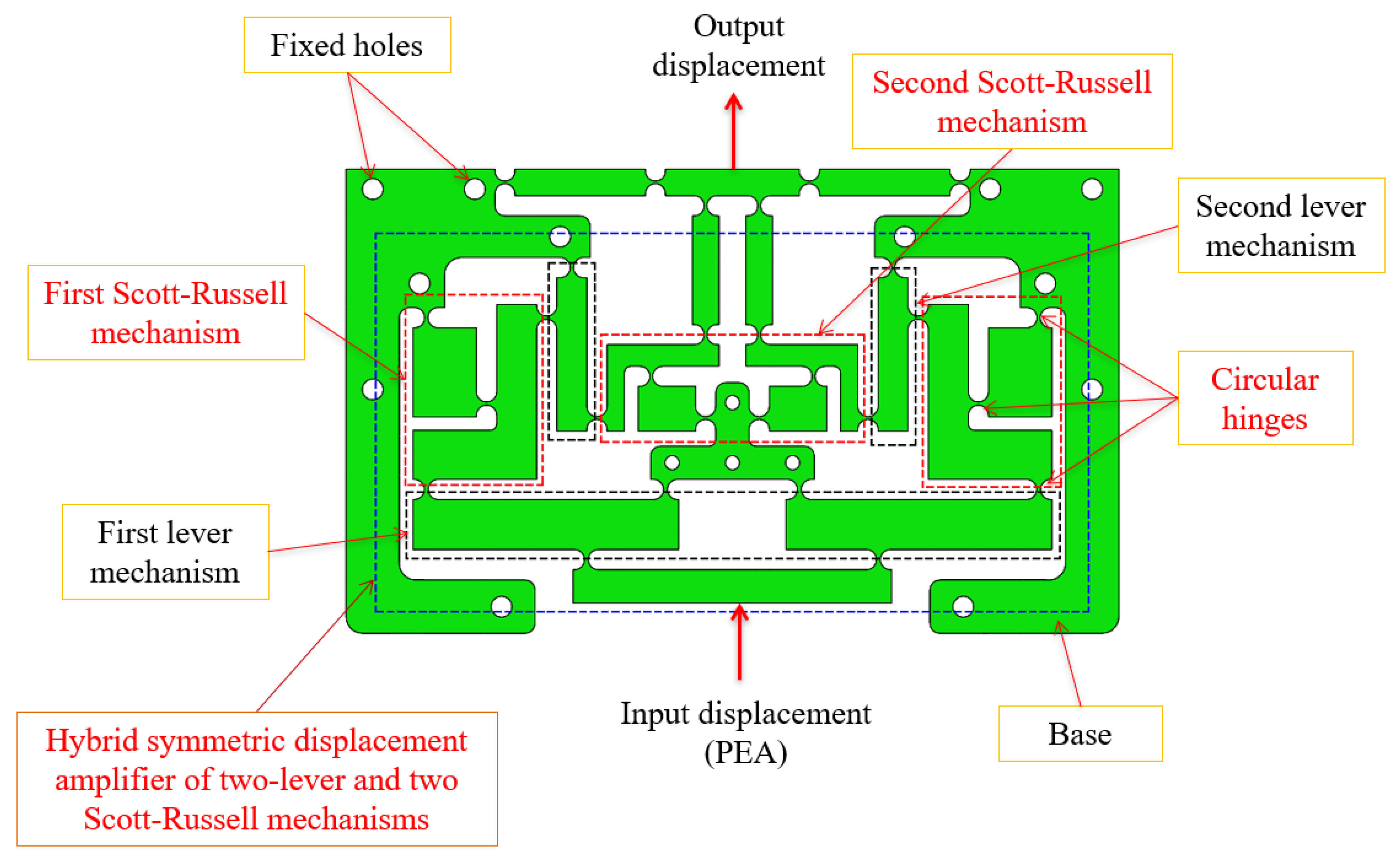
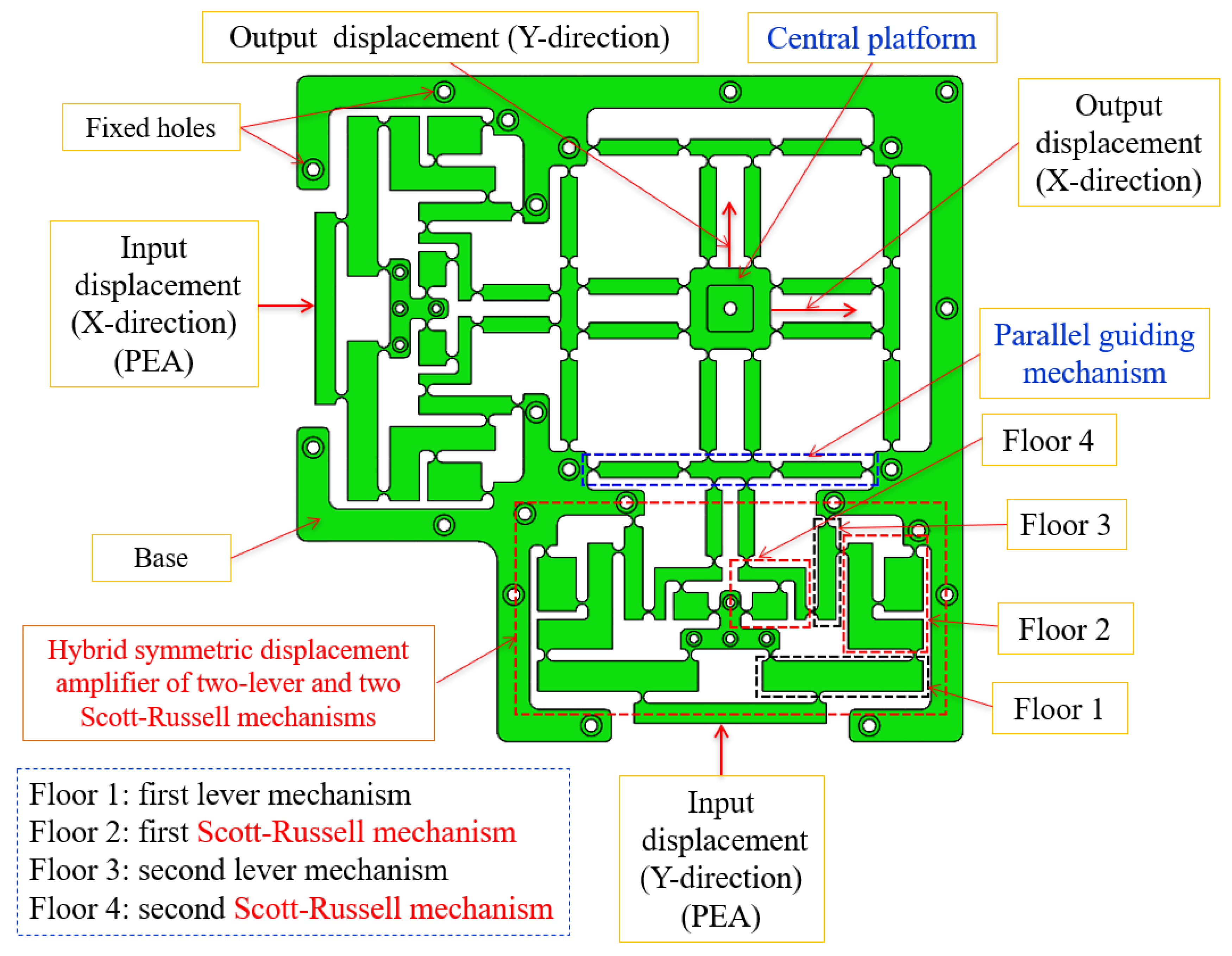
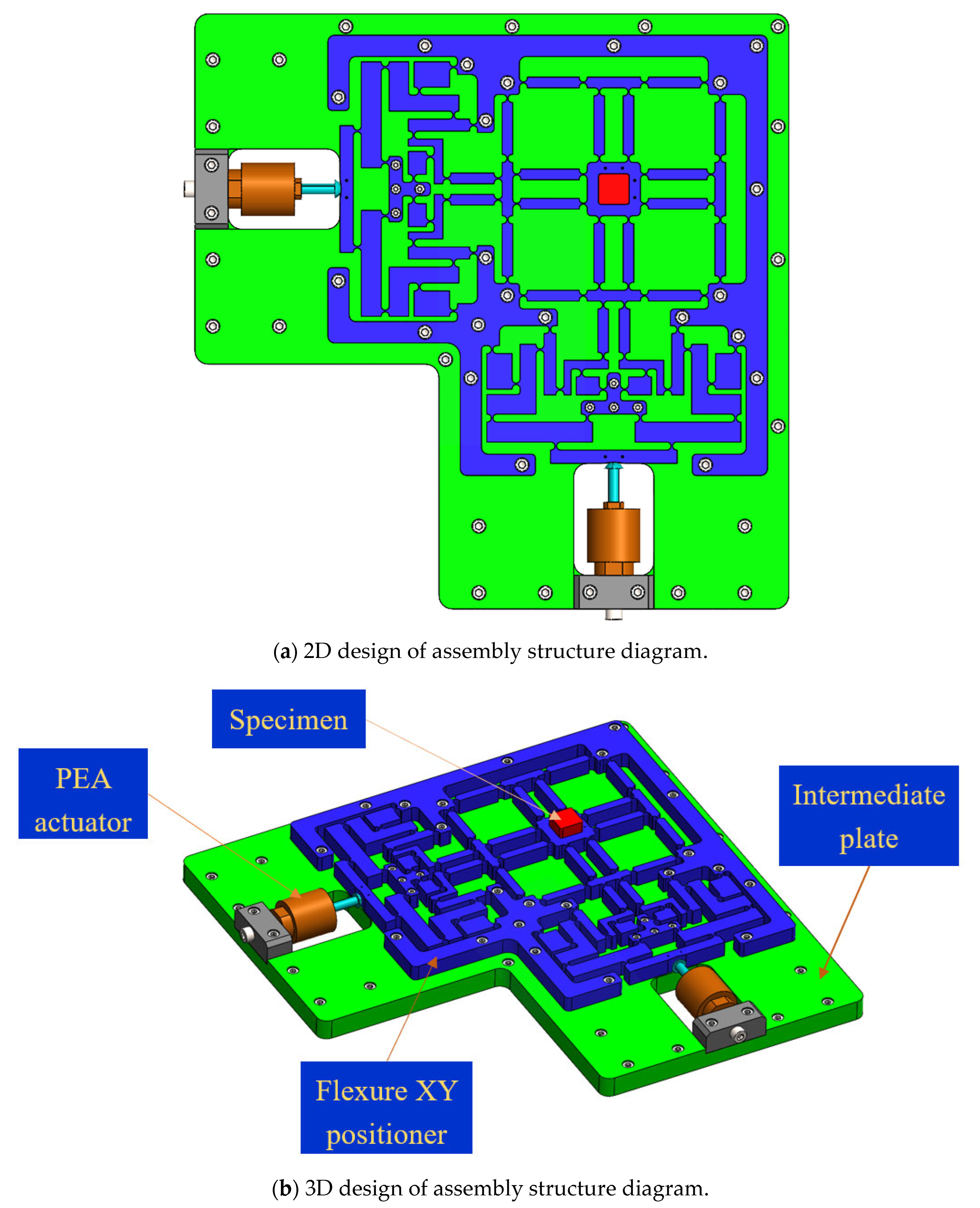
2. Mechanical Design
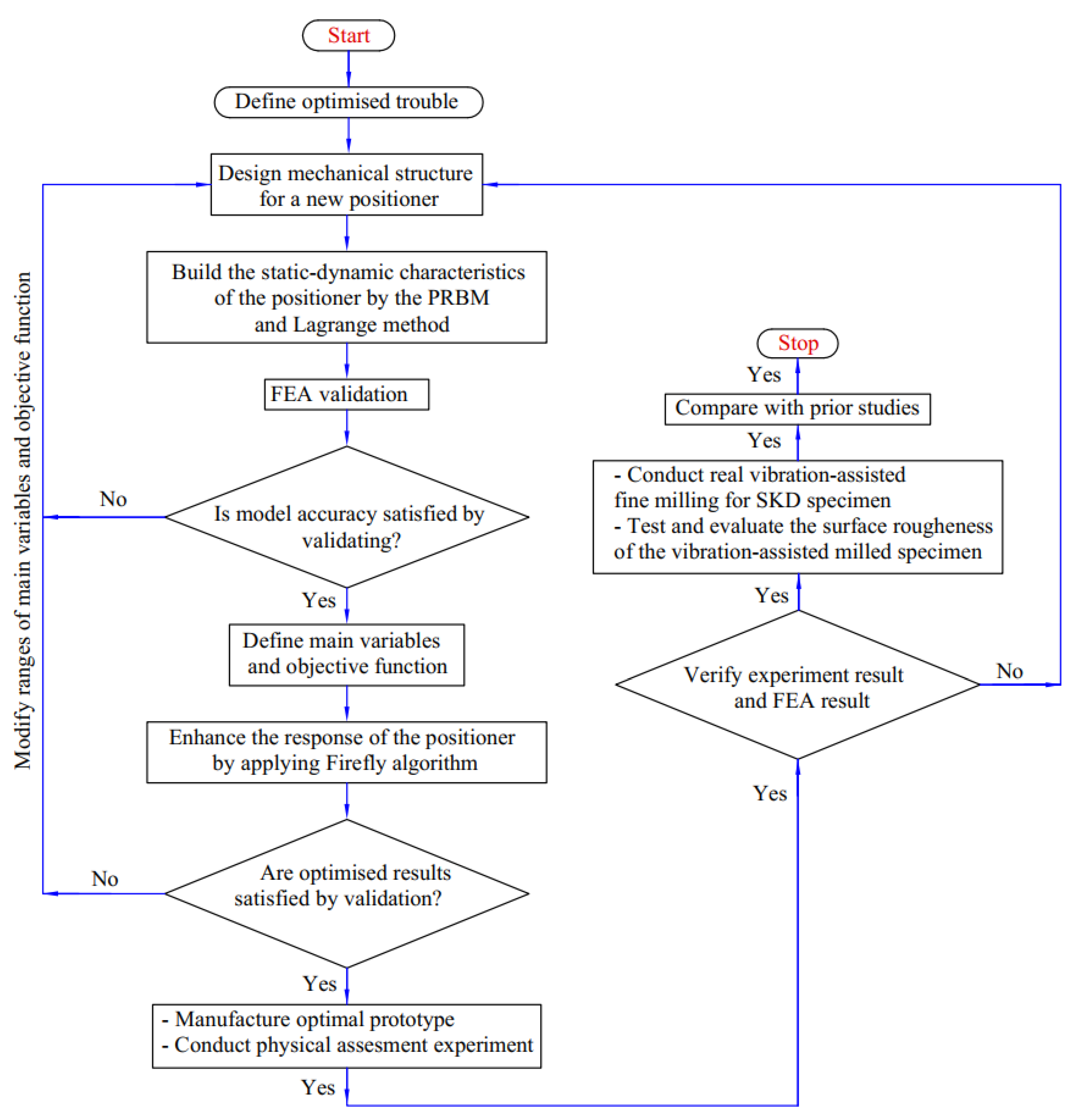
3. Proposed Hybrid Method
- (i)
- For the SKD11 non-resonant vibration-assisted fine milling, we developed a novel compliant positioner integrated with a new hybrid displacement amplifier with good technical performance.
- (ii)
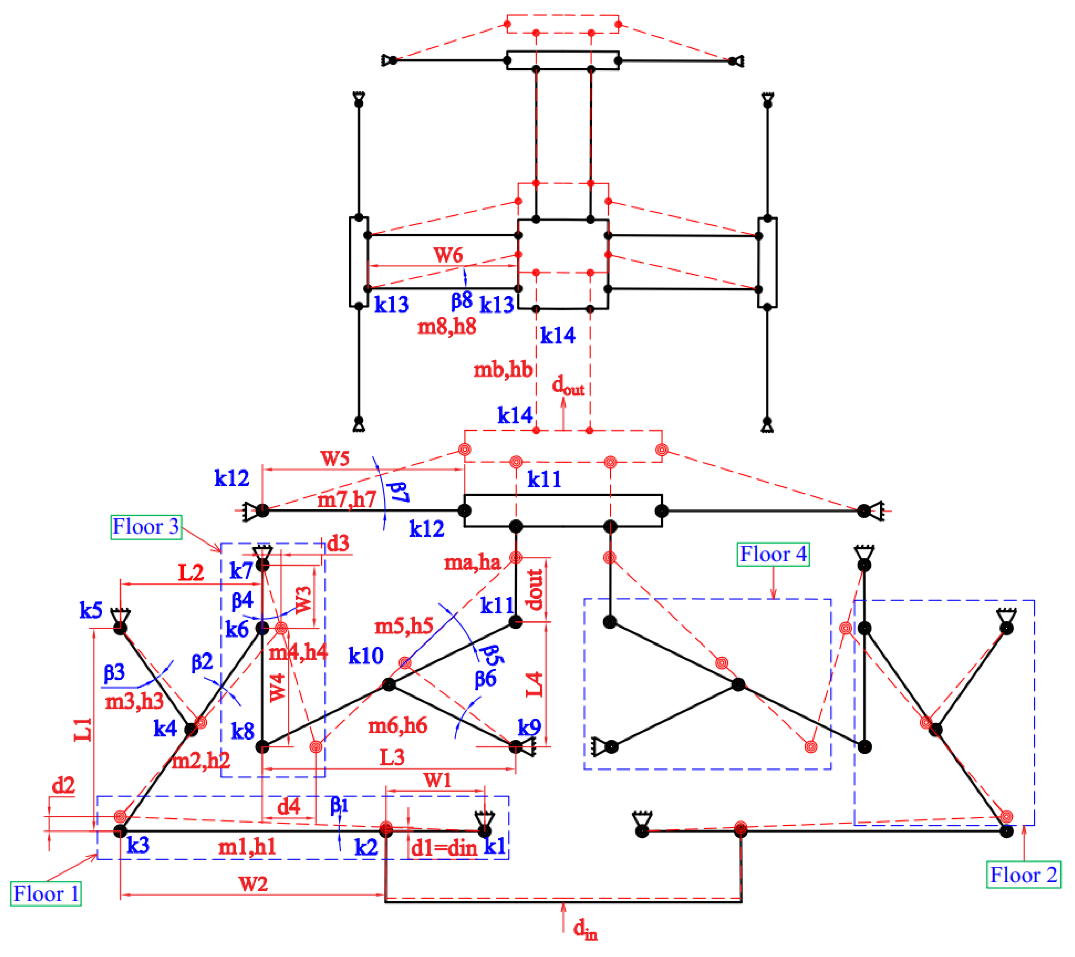
- The static–dynamic characteristics of the proposed positioner were built using the integration method of the PRBM and Lagrange technique.
- (iii)
- The analytical results of the quality response were verified using FEA analysis.
- (iv)
- The main parameters, the objective function, and limitations for design variables and the objective function were defined.
- (v)
- We optimized the proposed positioner’s main parameters to enhance the developed positioner’s quality response using the Firefly algorithm.
- (vi)
- The optimized analytical results were validated via FEA analysis.
- (vii)
- We fabricated the optimal prototype based on optimal design variables.
- (viii)
- A physical assessment experiment was conducted to verify the optimal results.
- (ix)
- We conducted real non-resonant vibration-assisted fine milling for the SKD 11 specimen in a frequency range [100 Hz, 1000 Hz].
- (x)
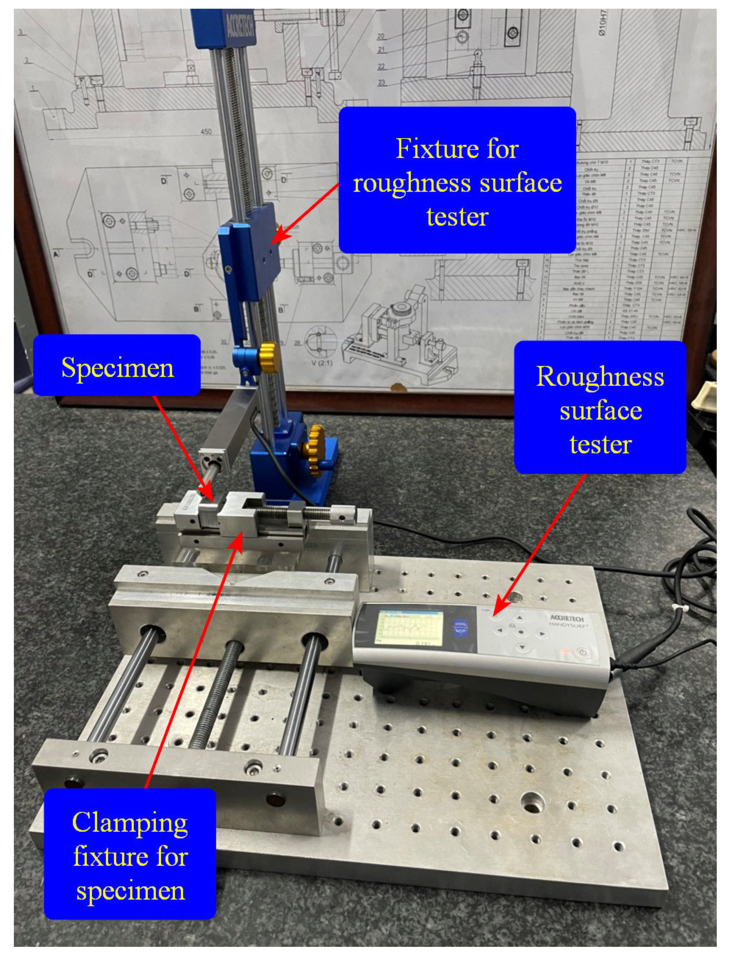
- We tested and evaluated the surface roughness of the vibration-assisted milled specimens.
- (xi)
- Comparisons with prior studies were undertaken.
4. Results Analysis and Discussion
4.1. Analytical Model Investigation
4.2. Working Stroke Analysis
4.3. Analytical Modelling Validation
4.4. Parameter Optimisation of the XY Positioner
4.5. Experimental Results
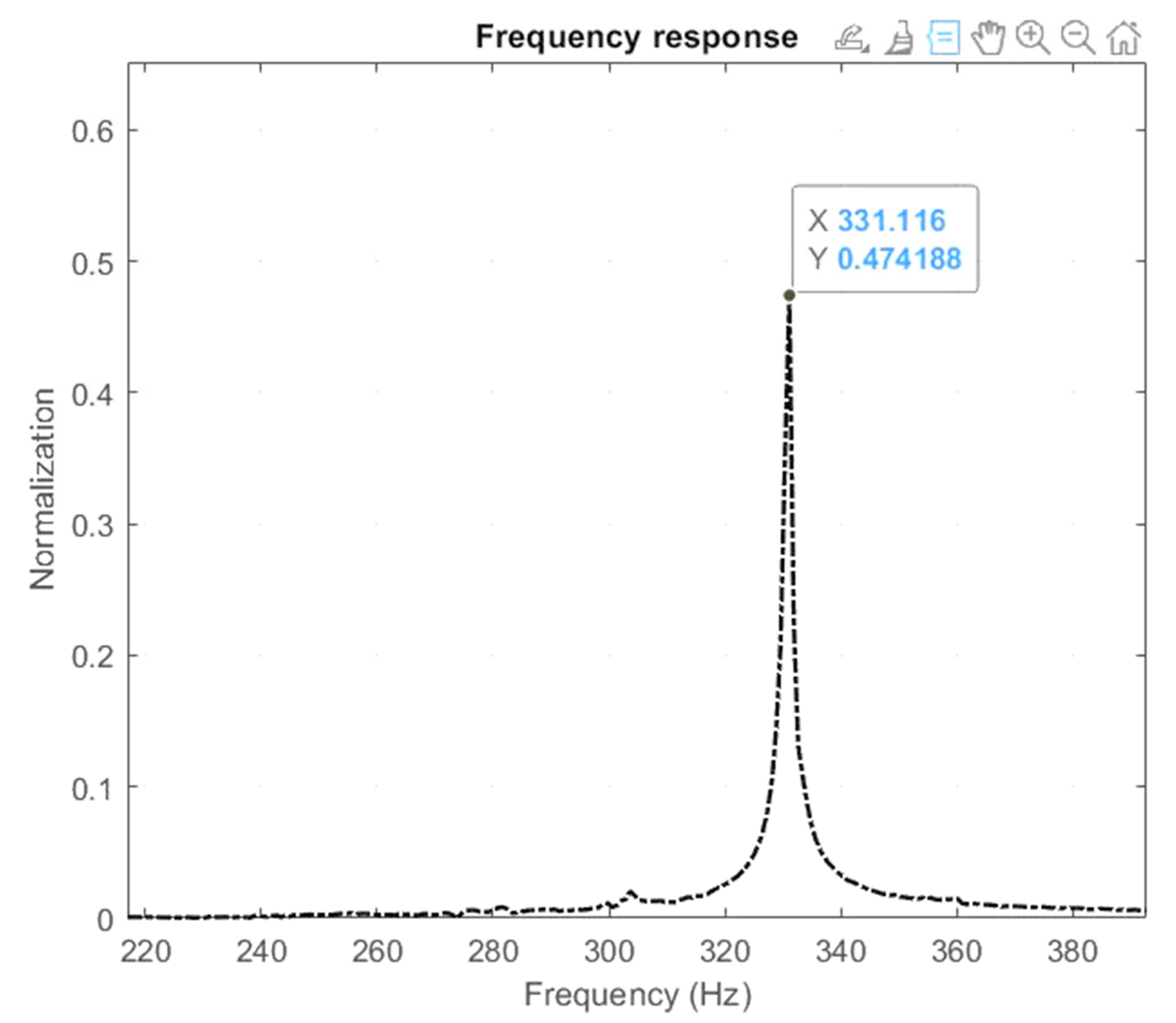
4.5.1. Resonant Frequency Testing
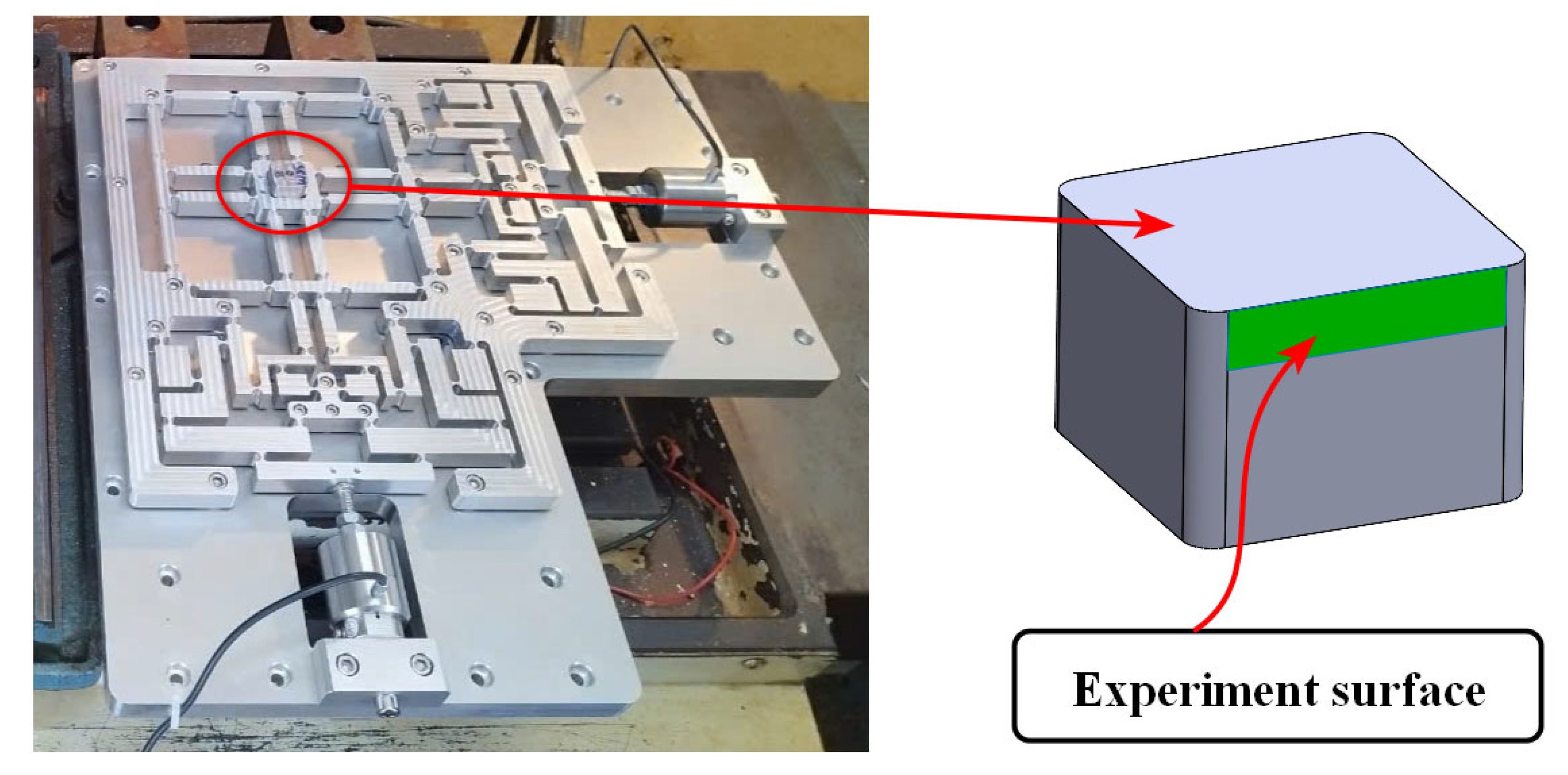
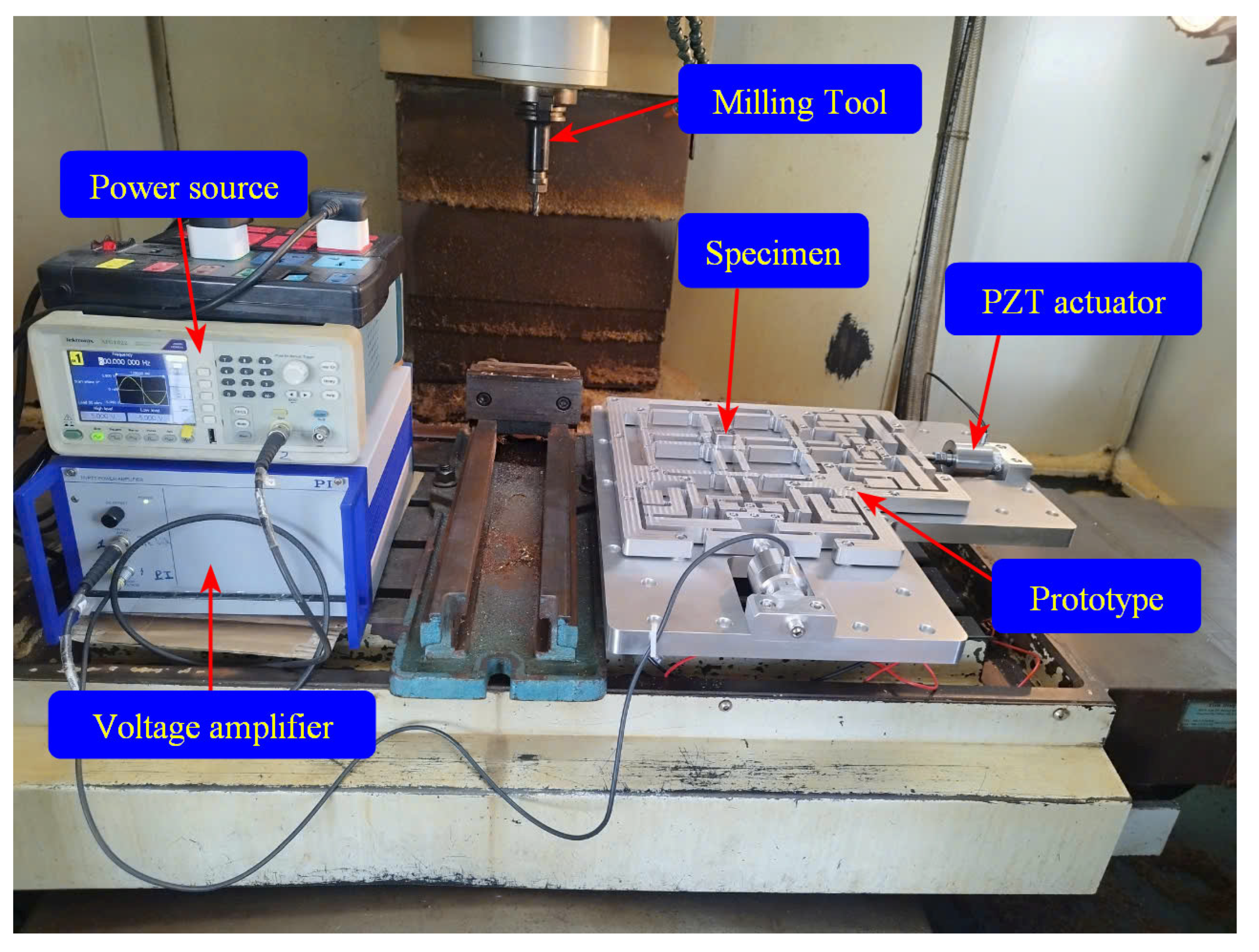
4.5.2. Examination of Experimental CNC Machining on a Fabricated Optimization Positioner
5. Conclusions
Author Contributions
Funding
Data Availability Statement
Acknowledgments
Conflicts of Interest
References
- Gan, J.; Xie, W.; Yang, W.; Lei, S.; Lei, B. Design of a novel Z-shaped flexure hinge and a 2-DOF XY precision positioning platform. Precis. Eng. 2025, 93, 459–469. [Google Scholar] [CrossRef]
- Lian, J.; An, D.; Chen, M.; Huang, W.; Liang, Z. Design and feedforward control of a two-degree-of-freedom positioning stage with bidirectional piezoelectric drive. Precis. Eng. 2023, 81, 158–166. [Google Scholar] [CrossRef]
- He, W.; Tang, X.; Ji, W.; Meng, L.; Wei, J.; Cao, D.; Ma, C.; Li, Q.; Lin, C. An improved multi-island genetic algorithm and its utilization in the optimal design of a micropositioning stage. Expert Syst. Appl. 2024, 257, 125029. [Google Scholar] [CrossRef]
- Ni, L.; Chen, G.; Hong, K.; Wang, G. Design and development of a compliant piezoelectric microgripper based on three-stage amplification. Microsyst. Technol. 2023, 29, 939–952. [Google Scholar] [CrossRef]
- Zhou, S.; Li, Y.; Wang, Q.; Lyu, Z. Integrated actuation and sensing: Toward intelligent soft robots. Cyborg Bionic Syst. 2024, 5, 0105. [Google Scholar] [CrossRef]
- Wu, Z.; Wang, X.; Cao, Y.; Zhang, W.; Xu, Q. Robotic Ultrasound Scanning End-Effector with Adjustable Constant Contact Force. Cyborg Bionic Syst. 2025, 6, 0251. [Google Scholar] [CrossRef]
- Zhang, Z.; Fan, W.; Long, Y.; Dai, J.; Luo, J.; Tang, S.; Lu, Q.; Wang, X.; Wang, H.; Chen, G. Hybrid-driven origami gripper with variable stiffness and finger length. Cyborg Bionic Syst. 2024, 5, 0103. [Google Scholar] [CrossRef]
- Chen, Q.; Zhang, X.; Zhang, H.; Zhu, B.; Chen, B. Topology optimization of bistable mechanisms with maximized differences between switching forces in forward and backward direction. Mech. Mach. Theory 2019, 139, 131–143. [Google Scholar] [CrossRef]
- Phan, T.V.; Truong, V.M.; Pham, H.T.; Nguyen, V.K. Design of a novel large-stroke compliant constant-torque mechanism based on chained beam-constraint model. J. Mech. Robot. 2024, 16, 1–38. [Google Scholar] [CrossRef]
- Zheng, L.; Chen, W.; Huo, D. Review of vibration devices for vibration-assisted machining. Int. J. Adv. Manuf. Technol. 2020, 108, 1631–1651. [Google Scholar] [CrossRef]
- Paniselvam, V.; Jin Tan, N.Y.; Anantharajan, S.K. A review on the design and application of compliant mechanism-based fast-tool servos for ultraprecision machining. Machines 2023, 11, 450. [Google Scholar] [CrossRef]
- Wu, H.; Meng, Y.; Meng, D.; Wang, R.; Zhu, Z.; Ren, M.; Zhang, X.; Zhu, L. Frequency response data-based feedforward control strategy for ultra-precision tool servo diamond turning of freeform surfaces. Mech. Syst. Signal Process. 2025, 232, 112706. [Google Scholar] [CrossRef]
- Gu, Y.; Liu, A.; Lin, J.; Chen, X.; Lu, F.; Sun, E. Development of decoupling device for vibration-assisted roller polishing of silicon carbide ceramics. IEEE Access 2020, 8, 219098–219113. [Google Scholar] [CrossRef]
- Gu, Y.; Duan, X.; Lin, J.; Yi, A.; Kang, M.; Jiang, J.; Zhou, W. Design, analysis, and testing of a novel 2-DOF vibration-assisted polishing device driven by the piezoelectric actuators. Int. J. Adv. Manuf. Technol. 2020, 111, 471–493. [Google Scholar] [CrossRef]
- Chen, X.; Gu, Y.; Lin, J.; Yi, A.; Kang, M.; Cang, X. Study on subsurface damage and surface quality of silicon carbide ceramic induced by a novel non-resonant vibration-assisted roll-type polishing. J. Mater. Process. Technol. 2020, 282, 116667. [Google Scholar] [CrossRef]
- Van Le, H.; Le, H.G.; Dao, T.P. Kinetostatic and dynamic analysis for a new 2-DOF compliant mechanism for potential application in vibration-assisted polishing. Int. J. Adv. Manuf. Technol. 2024, 135, 2413–2436. [Google Scholar] [CrossRef]
- Qin, Y.; Wu, H.; Li, Z.; Sun, N.; Sun, L. Design and analysis of a compliant end-effector for robotic polishing using flexible beams. Actuators 2022, 11, 284. [Google Scholar] [CrossRef]
- Zhang, J.; Zhao, L.; Li, L.; Ma, F.; Chen, G. Design of passive constant-force end-effector for robotic polishing of optical reflective mirrors. Chin. J. Mech. Eng. 2022, 35, 141. [Google Scholar] [CrossRef]
- Zheng, L.; Chen, W.; Huo, D.; Lyu, X. Design, analysis, and control of a two-dimensional vibration device for vibration-assisted micromilling. IEEE/ASME Trans. Mechatron. 2020, 25, 1510–1518. [Google Scholar] [CrossRef]
- Pham, H.T.; Nguyen, V.K.; Dang, Q.K.; Duong, T.V.A.; Nguyen, D.T.; Phan, T.V. Design optimization of compliant mechanisms for vibration assisted machining applications using a hybrid Six Sigma, RSM-FEM, and NSGA-II approach. J. Mach. Eng. 2023, 23, 135–158. [Google Scholar] [CrossRef]
- Dang, M.P.; Tran, C.T.; Le, H.G.; Tran, V.Q.A.; Tran, H.V. Modelling and Design Optimization of a Novel Compliant XY Positioner for Vibration-Assisted CNC Milling. Machines 2024, 12, 534. [Google Scholar] [CrossRef]
- Wu, Z.; Xu, Q. Survey on recent designs of compliant micro-/nano-positioning stages. Actuators 2018, 7, 5. [Google Scholar] [CrossRef]
- Chen, F.; Zhang, Q.; Gao, Y.; Dong, W. A review on the flexure-based displacement amplification mechanisms. IEEE Access 2020, 8, 205919–205937. [Google Scholar] [CrossRef]
- Gu, Y.; Chen, X.; Lin, J.; Lu, M.; Lu, F.; Zhang, Z.; Yang, H. Vibration-assisted roll-type polishing system based on compliant micro-motion stage. Micromachines 2018, 9, 499. [Google Scholar] [CrossRef]
- Yang, Y.; Wei, Y.; Lou, J.; Xie, F. Design and analysis of a new flexure-based XY stage. J. Intell. Mater. Syst. Struct. 2017, 28, 2388–2402. [Google Scholar] [CrossRef]
- Wu, Z.; Li, Y.; Hu, M. Design and optimization of full decoupled micro/nano-positioning stage based on mathematical calculation. Mech. Sci. 2018, 9, 417–429. [Google Scholar] [CrossRef]
- Dang, M.P.; Le, H.G.; Tran, C.T.; Nguyen, V.D.T.; Chau, N.L. Analysis and optimization of a novel compact compliant 2-DOF positioner for positioning to assess bio-specimen characteristics. Machines 2024, 12, 421. [Google Scholar] [CrossRef]
- Ding, B.; Yang, Z.X.; Xiao, X.; Zhang, G. Design of reconfigurable planar micro-positioning stages based on function modules. IEEE Access 2019, 7, 15102–15112. [Google Scholar] [CrossRef]
- Zhang, Q.; Zhao, J.; Shen, X.; Xiao, Q.; Huang, J.; Wang, Y. Design, modeling, and testing of a novel XY piezo-actuated compliant micro-positioning stage. Micromachines 2019, 10, 581. [Google Scholar] [CrossRef]
- Tian, Y.; Shirinzadeh, B.; Zhang, D.; Alici, G. Development and dynamic modelling of a flexure-based Scott–Russell mechanism for nano-manipulation. Mech. Syst. Signal Process. 2009, 23, 957–978. [Google Scholar] [CrossRef]
- Wu, H.; Tang, H.; Qin, Y. Design and test of a 2-DOF compliant positioning stage with antagonistic piezoelectric actuation. Machines 2024, 12, 420. [Google Scholar] [CrossRef]
- Ling, M.; Howell, L.L.; Cao, J.; Chen, G. Kinetostatic and dynamic modeling of flexure-based compliant mechanisms: A survey. Appl. Mech. Rev. 2020, 72, 030802. [Google Scholar] [CrossRef]
- Yuan, L.; Ling, M.; Lai, J.; Li, H.; Zhang, X. Graphic transfer matrix method for kinetostatic and dynamic analyses of compliant mechanisms. J. Mech. Robot. 2024, 16, 021009. [Google Scholar] [CrossRef]
- Zhu, W.L.; Zhu, Z.; Guo, P.; Ju, B.F. A novel hybrid actuation mechanism based XY nanopositioning stage with totally decoupled kinematics. Mech. Syst. Signal Process. 2018, 99, 747–759. [Google Scholar] [CrossRef]
- Zhu, J.; Hao, G.; Li, S.; Kong, X. A compact mirror-symmetrical XY compliant parallel manipulator for minimizing parasitic rotations. J. Mech. Des. 2022, 144, 073303. [Google Scholar] [CrossRef]
- Wu, S.; Ling, M. A dynamic Timoshenko beam constraint model for use in compliant mechanisms with intermediate deformation ranges. Precis. Eng. 2025, 94, 447–460. [Google Scholar] [CrossRef]
- Nguyen, H.D.; Van Le, H.; Tran, N.T.; Dang, M.P.; Van Tran, H.; Le, H.G.; Dao, T.P. A New Ant-Inspired 2-DOF Compliant Mechanism with High Frequency and Large Workspace for Potential Application in Material Testing. Arab. J. Sci. Eng. 2024, 1–20. [Google Scholar] [CrossRef]
- Yu, Y.Q.; Zhou, P.; Xu, Q.P. Kinematic and dynamic analysis of compliant mechanisms considering both lateral and axial deformations of flexural beams. Proc. Inst. Mech. Eng. Part C J. Mech. Eng. Sci. 2019, 233, 1007–1020. [Google Scholar] [CrossRef]
- Yang, X.S.; He, X. Firefly algorithm: Recent advances and applications. Int. J. Swarm Intell. 2013, 1, 36–50. [Google Scholar] [CrossRef]
- Sorgente, T.; Biasotti, S.; Manzini, G.; Spagnuolo, M. A survey of indicators for mesh quality assessment. Comput. Graph. Forum 2023, 42, 461–483. [Google Scholar] [CrossRef]
- Dang, M.P.; Le, H.G.; Van, M.N.; Chau, N.L.; Dao, T.P. Modeling and Optimization for a New Compliant 2-dof Stage for Locating Biomaterial Samples by an Efficient Approach of a Kinetostatic Analysis-Based Method and Neural Network Algorithm. Comput. Intell. Neurosci. 2022, 2022, 6709464. [Google Scholar] [CrossRef]


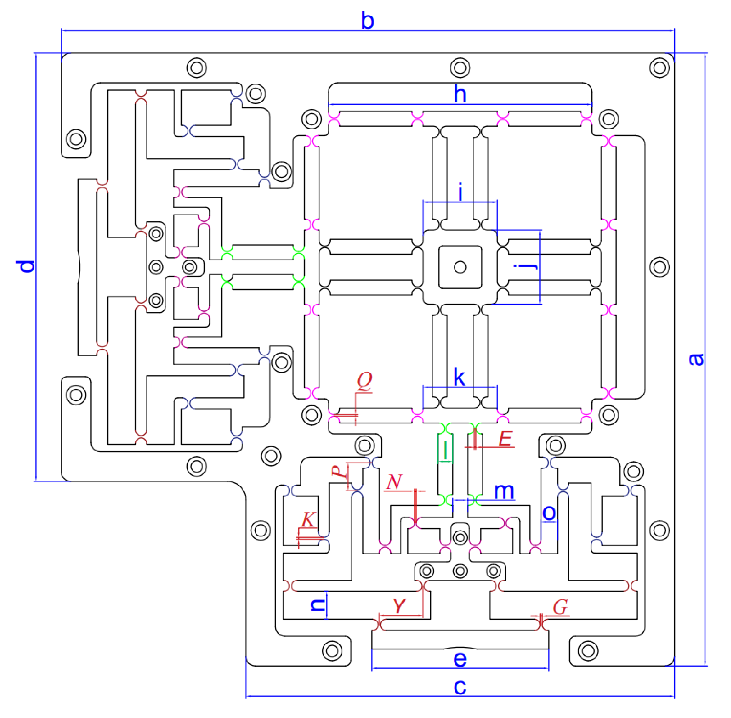
| Sign | Worth | Unit | Sign | Worth | Unit |
|---|---|---|---|---|---|
| G | 1 ≤ G ≤ 1.2 | mm | m | 8 | mm |
| K | 0.9 ≤ K ≤ 1 | mm | n | 15 | mm |
| N | 0.85 ≤ N ≤ 0.9 | mm | o | 9 | mm |
| E | 0.8 ≤ E ≤ 0.85 | mm | a | 330.5 | mm |
| Q | 0.7 ≤ Q ≤ 0.8 | mm | b | 330.5 | mm |
| Y | 20 ≤ Y ≤ 28 | mm | c | 231 | mm |
| P | 15 ≤ P ≤ 19 | mm | d | 231 | mm |
| j | 40 | mm | g | 16 | mm |
| k | 40 | mm | h | 142 | mm |
| l | 8 | mm | i | 40 | mm |
| Feature | Theoretical | FEA | Imprecision (%) |
|---|---|---|---|
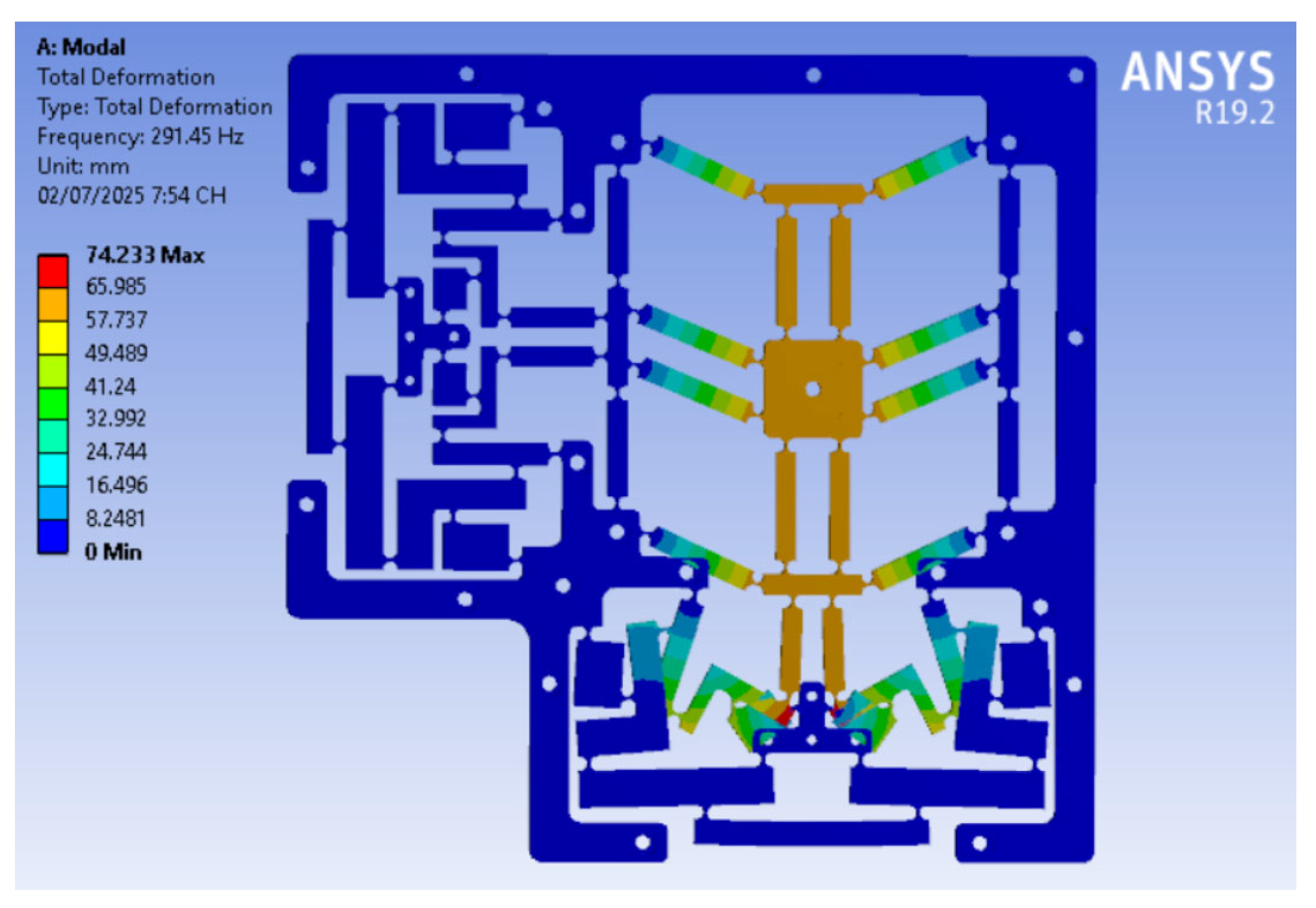
| f (Hz) | 298.55 | 291.45 | 2.436% |
| Feature | Analytical | FEA | Error (%) |
|---|---|---|---|
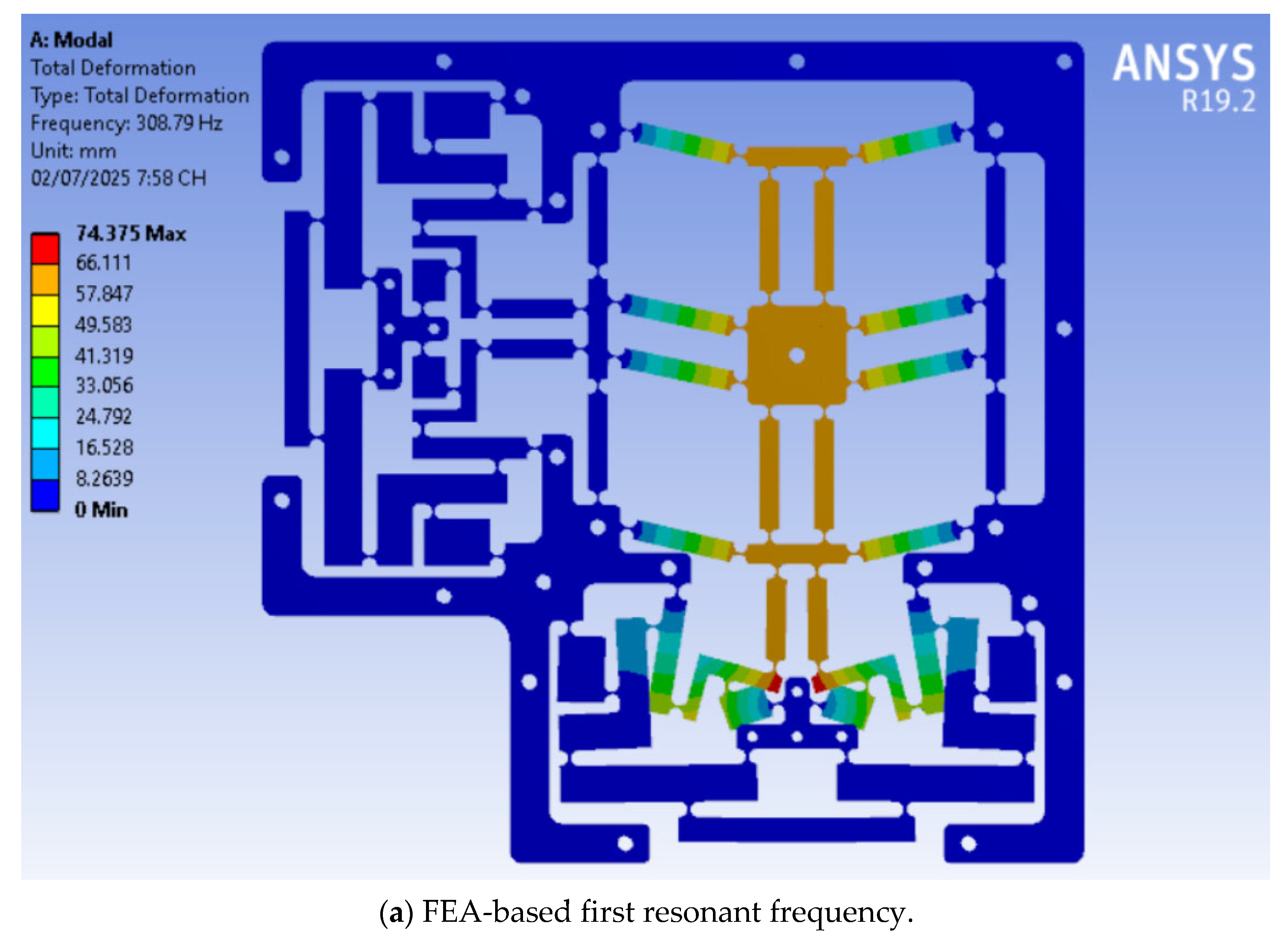
| f (Hz) | 318.16 | 308.79 | 3.04% |
| Attribute | FEA | Experiment | Inaccuracy (%) |
|---|---|---|---|
| f (Hz) | 308.79 | 331.116 | 7.23% |
| Attribute | Baseline Design | Optimized Design | Enhancement (%) |
|---|---|---|---|
| f (Hz) | 291.45 | 308.79 | 5.95% |
| No. | Investigated Frequency (Hz) | Surface Roughness (µm) (VAM) | Surface Roughness (µm) (Traditional Milling) |
|---|---|---|---|
| 1 | 100 | 0.601 | 0.638 |
| 2 | 200 | 1.067 | 0.638 |
| 3 | 300 | 0.196 | 0.638 |
| 4 | 400 | 0.187 | 0.638 |
| 5 | 500 | 0.3 | 0.638 |
| 6 | 600 | 0.308 | 0.638 |
| 7 | 700 | 0.283 | 0.638 |
| 8 | 800 | 0.475 | 0.638 |
| 9 | 900 | 1.855 | 0.638 |
| 10 | 1000 | 0.337 | 0.638 |
| Studies | Total Dimensions | First Resonant Frequency (Hz) | Workspace | Amplification Ratio |
|---|---|---|---|---|
| [25] | N/A | 168.22 | 150.3 µm × 147.9 µm | 7.48 |
| [41] | 451 mm × 451 mm | 112.1 | 787.63 μm × 794.5 μm | 7.79 |
| [24] | N/A | 220.43 | 112 µm × 89 µm | 7.55 |
| This study | 330.5 mm × 330.5 mm | 308.79 | 613.2 µm × 613.2 µm | 16.8 |
Disclaimer/Publisher’s Note: The statements, opinions and data contained in all publications are solely those of the individual author(s) and contributor(s) and not of MDPI and/or the editor(s). MDPI and/or the editor(s) disclaim responsibility for any injury to people or property resulting from any ideas, methods, instructions or products referred to in the content. |
© 2025 by the authors. Licensee MDPI, Basel, Switzerland. This article is an open access article distributed under the terms and conditions of the Creative Commons Attribution (CC BY) license (https://creativecommons.org/licenses/by/4.0/).
Share and Cite
Dang, M.P.; Luong, A.K.; Le, H.G.; Tran, C.T. Optimal Design for a Novel Compliant XY Platform Integrated with a Hybrid Double Symmetric Amplifier Comprising One-Lever and Scott–Russell Mechanisms Arranged in a Perpendicular Series Layout for Vibration-Assisted CNC Milling. Micromachines 2025, 16, 793. https://doi.org/10.3390/mi16070793
Dang MP, Luong AK, Le HG, Tran CT. Optimal Design for a Novel Compliant XY Platform Integrated with a Hybrid Double Symmetric Amplifier Comprising One-Lever and Scott–Russell Mechanisms Arranged in a Perpendicular Series Layout for Vibration-Assisted CNC Milling. Micromachines. 2025; 16(7):793. https://doi.org/10.3390/mi16070793
Chicago/Turabian StyleDang, Minh Phung, Anh Kiet Luong, Hieu Giang Le, and Chi Thien Tran. 2025. "Optimal Design for a Novel Compliant XY Platform Integrated with a Hybrid Double Symmetric Amplifier Comprising One-Lever and Scott–Russell Mechanisms Arranged in a Perpendicular Series Layout for Vibration-Assisted CNC Milling" Micromachines 16, no. 7: 793. https://doi.org/10.3390/mi16070793
APA StyleDang, M. P., Luong, A. K., Le, H. G., & Tran, C. T. (2025). Optimal Design for a Novel Compliant XY Platform Integrated with a Hybrid Double Symmetric Amplifier Comprising One-Lever and Scott–Russell Mechanisms Arranged in a Perpendicular Series Layout for Vibration-Assisted CNC Milling. Micromachines, 16(7), 793. https://doi.org/10.3390/mi16070793