
Transmission of LG Modes in High-Capacity 16 × 10 Gbps FSO System Using FBG Sensors Under Different Channel Scenarios


Abstract
1. Introduction
1.1. Related Work
1.2. Motivation
1.3. Major Contributions
- To design a high-speed 16 × 10 Gbps MDM-FSO system using uniform FBG sensors.
- To evaluate the system performance as well as comparison analysis for different LG modes under the impact of different weather conditions, weak-to-strong turbulence, and distribution models, i.e., gamma–gamma (GG) and log-normal (LN).
- System performance analysis for varied FSO range, variable parameters of sensor (temperature and index modulation), system gain and OSNR, in terms of bit-error-rate (BER) performance, eye patterns, and optical spectra.
- To validate the feasibility of the proposed sensor-based MDM-FSO system via comparisons with prior works in terms of different parameters.
2. Proposed Design
3. Results and Discussions
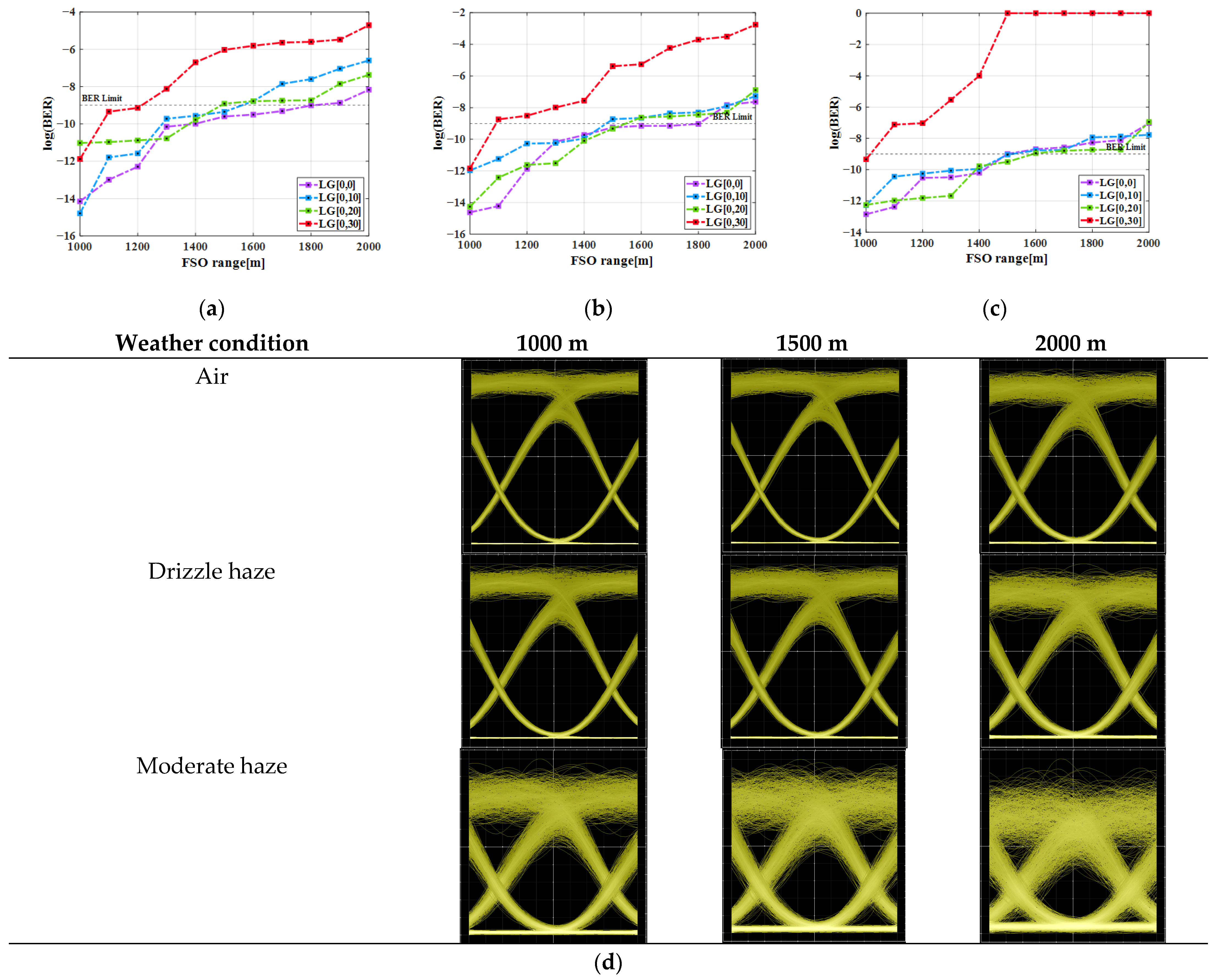
3.1. System Performace Under Atmospheric Conditions w.r.t. FSO Link
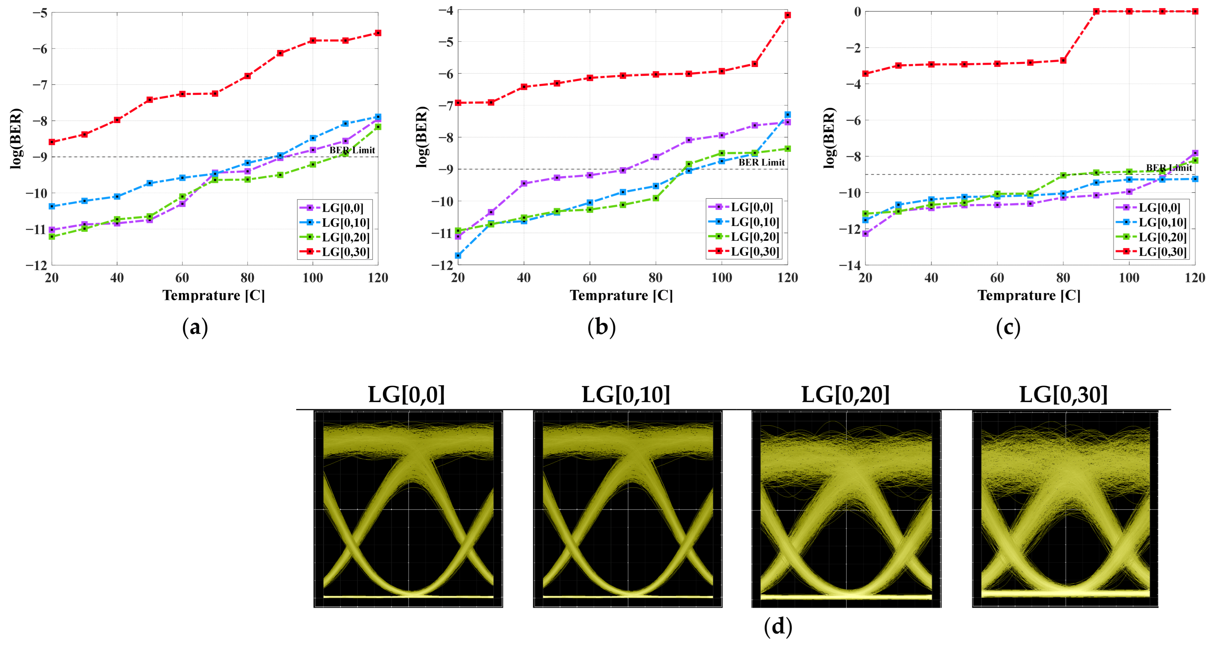
3.2. System Performace Under Atmospheric Conditions w.r.t. Sensor Temperature
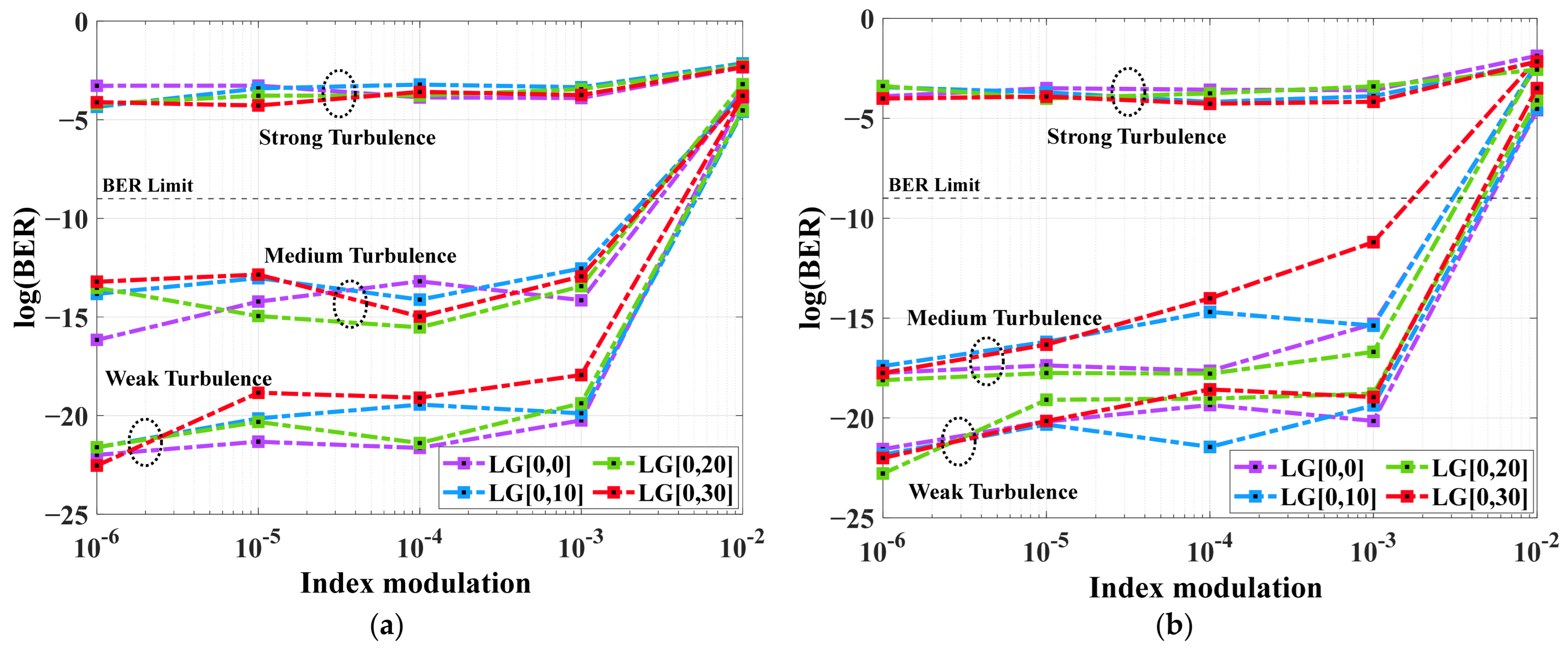
3.3. System Performace Under Different Channel Modes with Atmospheric Turbulence w.r.t. Index Modulation in Sensor
3.4. Impact of Different Atmospheric Conditions on the System Performance
3.5. System Performance Comparisons with Existing Ones
4. Conclusions
Author Contributions
Funding
Institutional Review Board Statement
Informed Consent Statement
Data Availability Statement
Conflicts of Interest
References
- Syriopoulos, G.; Kyriazi, E.; Prousalidi, T.; Ntanos, A.; Stathis, A.; Kourelias, P.; Toumasis, P.; Zervos, H.; Giannoulis, G.; Poulopoulos, G.; et al. Co-Existence of SiPh Sensing Link and Real World Traffic over 100 m FSO Link for 6G Deployments. IEEE Photonics Technol. Lett. 2025, 37, 529–532. [Google Scholar] [CrossRef]
- Tefera, M.A.; Manie, C.; Yao, C.K.; Fan, T.P.; Peng, P.C. Meta-Learning for Boosting the Sensing Quality and Utility of FSO-Based Multichannel FBG Sensor System. IEEE Sens. J. 2023, 23, 31506–31512. [Google Scholar] [CrossRef]
- Dehnaw, A.M.; Manie, Y.C.; Du, L.-Y.; Yao, C.-K.; Jiang, J.-W.; Liu, B.-X. Integrated Sensor-Optics Communication System Using Bidirectional Fiber and FSO Channels and Hybrid Deep Learning Techniques. Sensors 2023, 23, 8434. [Google Scholar] [CrossRef] [PubMed]
- Šišovas, L.; Čeponis, A.; Mažeika, D.; Borodinas, S. Development of Piezoelectric Inertial Rotary Motor for Free-Space Optical Communication Systems. Micromachines 2024, 15, 1495. [Google Scholar] [CrossRef] [PubMed]
- Zeng, H.; Wang, H.; Wang, K.; Yu, X.; Zhang, Z. Enhancing Robustness in Hybrid FSO/RF Systems: A Feedback-Free Approach Leveraging Deep Learning for Real-Time Power Allocation. IEEE Internet Things J. 2025, 12, 24358–24373. [Google Scholar] [CrossRef]
- Dai, L.; Ding, Y.; Zhang, H.; Qi, J.; Shi, H.; Chu, J.; Zhang, L.; Shen, L.; Liao, Z.; Zhou, S.; et al. A Cladding-Pumped Device for Modal Gain Equilization Based on Rippled Few Mode Fiber. IEEE Photonics J. 2025, 17, 7100306. [Google Scholar] [CrossRef]
- Zhang, W.; Ye, M.; Li, Y.; Liu, L.; Guo, X.; Yu, Y. Low-Crosstalk High-Order Mode Silicon Fiber-Chip Coupler by Utilizing Apodized Double Part Gratings With Mode Selective Trident. IEEE Photonics J. 2023, 15, 6600704. [Google Scholar] [CrossRef]
- Hayle, S.T.; Manie, Y.C.; Yao, C.K.; Yeh, T.Y.; Yu, C.H.; Peng, P.C. Hybrid of Free Space Optics Communication and Sensor System Using IWDM Technique. J. Light. Technol. 2022, 40, 5862–5869. [Google Scholar] [CrossRef]
- Sinha, S.; Kumar, C. Evaluation of a High-Speed Hybrid OAM-OFDM-MDM Multiplexed Coherent FSO System under Desert Conditions. Opt. Appl. 2023, LIII, 431–445. [Google Scholar] [CrossRef]
- Zhou, H.; Lynn, B.; Song, H.; Hu, N.; Tur, M.; Zou, K.; Su, X.; Zhao, Z.; Pang, K.; Almaiman, A.; et al. Demonstration of Turbulence Resiliency in a Mode-, Polarization-, and Wavelength-Multiplexed Free-Space Optical Link Using Pilot-Assisted Optoelectronic Beam Mixing. J. Light. Technol. 2022, 40, 588–596. [Google Scholar] [CrossRef]
- Hu, Z.; Chen, Z.; Li, Y.; Benton, D.M.; Ali, A.A.I.; Patel, M.; Lavery, M.P.J.; Ellis, A.D. Adaptive Transceiver Design for High-Capacity Multi-Modal Free-Space Optical Communications With Commercial Devices and Atmospheric Turbulence. J. Light. Technol. 2023, 41, 3397–3406. [Google Scholar] [CrossRef]
- Wang, W.; Wang, P.; Cao, T.; Tian, H.; Zhang, Y.; Guo, L. Performance Investigation of Underwater Wireless Optical Communication System Using M -Ary OAMSK Modulation over Oceanic Turbulence. IEEE Photonics J. 2017, 9, 7905315. [Google Scholar] [CrossRef]
- Mandal, P.; Sarkar, N.; Santra, S.; Dutta, B.; Kuiri, B.; Mallick, K.; Patra, A.S. Hybrid WDM-FSO-PON with Integrated SMF/FSO Link for Transportation of Rayleigh Backscattering Noise Mitigated Wired/Wireless Information in Long-Reach. Opt. Commun. 2022, 507, 127594. [Google Scholar] [CrossRef]
- Kaushal, H.; Kaddoum, G. Optical Communication in Space: Challenges and Mitigation Techniques. IEEE Commun. Surv. Tutorials 2017, 19, 57–96. [Google Scholar] [CrossRef]
- Ahmed, A.-G.S.; Salleh, M.F.M.; Salem, A.A.; Shaddad, R.Q.; Sheikh, U.U.; Algeelani, N.A.; Almohamad, T.A. A Survey of Free Space Optics (FSO) Communication Systems, Links, and Networks. IEEE Access 2020, 9, 7353–7373. [Google Scholar] [CrossRef]
- Khalighi, M.A.; Uysal, M. Survey on Free Space Optical Communication: A Communication Theory Perspective. IEEE Commun. Surv. Tutor. 2014, 16, 2231–2258. [Google Scholar] [CrossRef]
- Ali, H.A.E.M.; Said, E.S.S.A.; Yousef, M.E. Effect of Environmental Parameters on the Performance of Optical Wireless Communications. Int. J. Opt. 2019, 2019, 1–12. [Google Scholar] [CrossRef]
- Elamassie, M.; Member, A.; Uysal, M. Vertical Underwater Visible Light Communication Links: Channel Modeling and Performance Analysis. IEEE Trans. Wirel. Commun. 2020, 19, 6948–6959. [Google Scholar] [CrossRef]
- Yu, S.; Ding, J.; Fu, Y.; Ma, J.; Tan, L.; Wang, L. Novel Approximate and Asymptotic Expressions of the Outage Probability and BER in Gamma–Gamma Fading FSO Links with Generalized Pointing Errors. Opt. Commun. 2019, 435, 289–296. [Google Scholar] [CrossRef]
- Agrawal, G.P. Applications of Nonlinear Fiber Optics; Academic Press: Cambridge, MA, USA, 2008; pp. 1–508. ISBN 978-0-12-374302-2. [Google Scholar]
- Ji, J.; Huang, Q.; Chen, X.; Sun, L. Performance Analysis and Experimental Investigation of Physical-Layer Security in OCDMA-Based Hybrid FSO/Fiber Wiretap Channel. IEEE Photonics J. 2019, 11, 1–20. [Google Scholar] [CrossRef]
- Nguyen, D.N.; Vallejo, L.; Bohata, J.; Ortega, B.; Ghassemlooy, Z.; Zvanovec, S. Wideband QAM-over-SMF/Turbulent FSO Downlinks in a PON Architecture for Ubiquitous Connectivity. Opt. Commun. 2020, 475, 126281. [Google Scholar] [CrossRef]
- García-Zambrana, A.; Castillo-Vázquez, B.; Castillo-Vázquez, C. Asymptotic Error-Rate Analysis of FSO Links Using Transmit Laser Selection over Gamma-Gamma Atmospheric Turbulence Channels with Pointing Errors. Opt. Express 2012, 20, 2096. [Google Scholar] [CrossRef] [PubMed]
- Hang, Z.; Kumar, S.; Huang, Y.-P. Mode Selective Image Upconversion over Turbulence. In Proceedings of the Frontiers in Optics + Laser Science APS/DLS, Washington, DC, USA, 15–19 September 2019; pp. 1–8. [Google Scholar]
- Viswanath, A.; Jain, V.K.; Kar, S. Analysis of Earth-to-Satellite Free-Space Optical Link Performance in the Presence of Turbulence, Beam-Wander Induced Pointing Error and Weather Conditions for Different Intensity Modulation Schemes. IET Commun. 2015, 9, 2253–2258. [Google Scholar] [CrossRef]
- Ragheb, A.M.; Tareq, Q.; Esmail, M.A.; Fathallah, H.; Alshebeili, S.A.; Khan, M.Z.M. Sub-THz Signal Transmission in Harsh Environments Using L-Band Quantum-Dash Laser Source: Experiments and Modeling. IEEE J. Sel. Top. Quantum Electron. 2023, 29, 1–9. [Google Scholar] [CrossRef]


| Component | Parameters | Value | Unit |
|---|---|---|---|
| Laser | Frequency | 193.1–193.4 | THz |
| Channel spacing | 100 | GHz | |
| Input power | 10 | dBm | |
| Bit generator | Bit rate | 10 | Gbps |
| Uniform FBG sensor | Bragg wavelength | 1550 | nm |
| Index modulation | 10−6 to 10−2 | ||
| Length | 10 | mm | |
| Temperature | 20–120 | °C | |
| Thermal expansion coefficient | 5.50 × 10⁻⁷ | /C | |
| Thermo-optic coefficient | 8.60 × 10⁻⁶ | /C | |
| Mode generator | LG[0,0], LG[0,10], LG[0,20], LG[0,30] | ||
| MZM modulator | Extinction ratio | 30 | dB |
| FSO | Range | 1000–2000 | m |
| Index refraction structure | 10−13–10−17 | m−2/3 | |
| Weather condition | 0.22 (clear air), 1.5 (Drizzle haze) 4.2 (Moderate haze) | dB/km | |
| Tx/Rx aperture diameter | 10/20 | cm | |
| Transceiver loss | 0.1 | dB | |
| Geometric loss | Yes | ||
| Additional loss | 0.1 | dB | |
| Beam divergence | 2 | mrad | |
| Free space path loss | Yes | ||
| Spatial receiver | Responsitivity | 0.9 | A/W |
| Dark current | 10 | nA | |
| Thermal noise | 10−25 | W/Hz | |
| Temperature | 300 | K | |
| Shot noise | Yes | ||
| Width | 10 | µm | |
| Low pass filter cut-off frequency | 0.75 × Bit rate | Hz | |
| 1:4 Power combiner/splitter | Insertion loss | 2 | dB |
| Weather | LG[0,0] | LG[0,10] | LG[0,20] | LG[0,30] |
|---|---|---|---|---|
| Clear air | 1900 m | 1600 m | 1550 m | 1200 m |
| Drizzle haze | 1800 m | 1510 m | 1500 m | 1100 m |
| Moderate haze | 1550 m | 1500 m | 1500 m | 1000 m |
| Weather | LG[0,0] | LG[0,10] | LG[0,20] | LG[0,30] |
|---|---|---|---|---|
| Clear air | 1000 | 900 | 900 | 200 |
| Drizzle haze | 800 | 900 | 800 | <200 |
| Moderate haze | 1100 | 1200 | 1100 | <200 |
| Turbulence | (m−2/3) | m | n | SI | SR | |
|---|---|---|---|---|---|---|
| Weak | 10−17 | 0.5 | 10 | 9 | 0.2 | 1 |
| Medium | 10−14 | 1.1 | 4.2 | 2.2 | 0.80 | 0.5 |
| Strong | 10−12 | 1.5 | 2.14 | 1.97 | 1.21 | 0 |
| Turbulence | LG[0,0] | LG[0,10] | LG[0,20] | LG[0,30] | ||||
|---|---|---|---|---|---|---|---|---|
| GG | LN | GG | LN | GG | LN | GG | LN | |
| Weak | −21.99 to −3.88 | −21.56 4.59 | −21.61 to −4.6 | −21.84 to -4.53 | −21.6 to −4.53 | −22.78 to −4.1 | −22.53 to −3.85 | −22 to −3.49 |
| Medium | −16.16 to −3.51 | −19.74 −4.35 | −13.83 to −3.65 | −19.4 to -4.23 | −13.52 to −3.2 | −19.75 to −4.25 | −13.21 to −3.78 | −19.75 to −4.04 |
| Strong | −3.28 to −2.34 | −3.9 −1.87 | −4.35 to −2.14 | −3.44 to −2.19 | −3.78 to −2.26 | −3.38 to −2.56 | −4.11 to −2.33 | −4.01 to −2.15 |
| Reference | Maximum Range | No. of Channels | Data Rate/ Channel (Gbps) | Mode(s) | Sensor | Operating Wavelength(s)/Frequency(s) | Weather Conditions | Turbulence | FSO Channel Model | Complexity and Cost |
|---|---|---|---|---|---|---|---|---|---|---|
| [9] | 1.5 km (FSO) | 1 | 120 Gbps | OAM | - | 1550 nm | Low and heavy dust | Strong | Gamma- Gamma | High |
| [26] | 11.6 km (SMF), 6 m (FSO) | - | 20 Gbps | - | - | 1609.98– 1610.84 nm | Fog, smoke | - | - | High |
| [10] | - | 8 | 2 Gbps | OAM | - | - | - | Weak and strong | - | High |
| [1] | 100 m | 1 | 10 Gbps | - | Photonic | 1529–1568.2 nm | - | - | - | Moderate |
| [8] | 2 m (FSO) | 4 | 2.5 Gbps | - | FBG | 1520–1560 nm | - | - | - | High |
| [3] | 25 km (SMF) + 2 m (FSO) | - | - | - | FBG | 1544–1548 nm | - | - | - | High |
| [2] | - | - | - | - | FBG | 1544.59, 1545.52 and 1546.53 nm | - | - | - | - |
| [5] | 2 km (FSO) | 1 | - | - | - | 1550 nm | Air, rain, snow | - | Malaga | Moderate |
| This work | 1.9 km (FSO) | 16 | 10 Gbps | LG | FBG | 193.1, 193.2, 193.3 and 193.4 THz | Air, drizzle and moderate haze | Weak-to- strong | Gamma- Gamma, Log- Normal | Low |
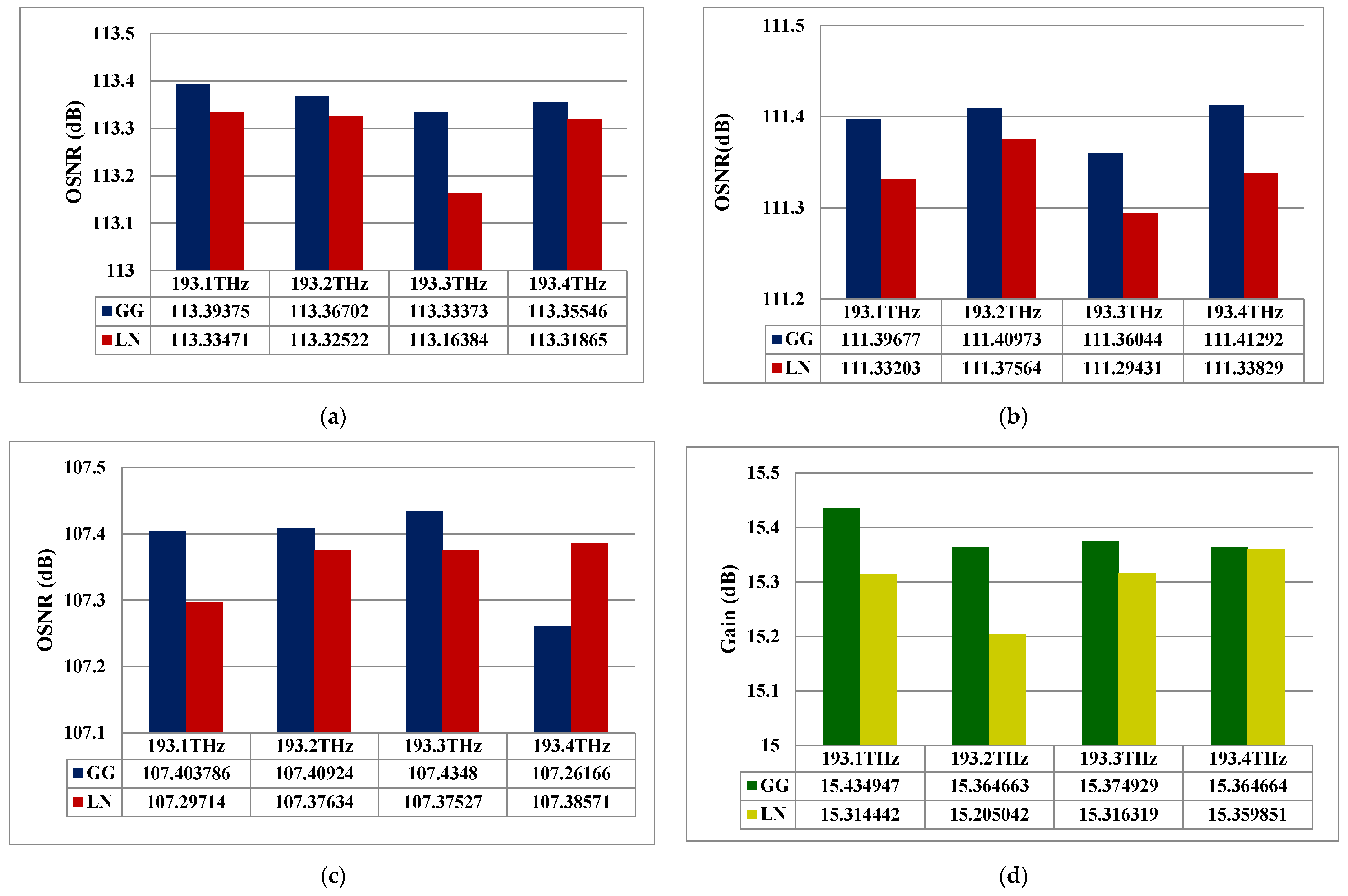
| Reference | Input Power | Modulation and Detection | Channel Capacity | Aperture (Tx/Rx) | Loss | OSNR | Divergence Angle | BER Limit | Modes |
|---|---|---|---|---|---|---|---|---|---|
| [9] | 20 dBm | OFDM | 120 Gbps | 10/10 cm | Not considered | 21.9 dB | 0.02 mrad | 10−3 | LG{[0], [0,10]} |
| [26] | 11 dBm | Quadrature Phase Shift Keying (QPSK) | 20 Gbps | - | Free space path | - | - | 10−3 | - |
| [10] | 3.7 dBm | QPSK | 8×2 Gbps | - | Mode-dependent loss | - | - | 10−3 | OAM [l = +1 & l = −2] |
| [1] | 2.1 dBm | OOK | 10 Gbps | - | Insertion, attenuation, coupling | - | - | - | - |
| [8] | - | - | 4 × 2.5 Gbps | - | - | - | - | 10−9 | - |
| [5] | 20 dBm | OOK | - | 0.05 m (Rx) | Attenuation, pointing error | - | - | - | - |
| This work | 10 dBm | OOK/DD | 16 × 10 Gbps | 10/20 cm | Transceiver, Geometric, Additional and Free space path | 113.39 dB | 2 mrad | 10−9 | LG{[0], [0,10], [0,20] and [0,30]} |
Disclaimer/Publisher’s Note: The statements, opinions and data contained in all publications are solely those of the individual author(s) and contributor(s) and not of MDPI and/or the editor(s). MDPI and/or the editor(s) disclaim responsibility for any injury to people or property resulting from any ideas, methods, instructions or products referred to in the content. |
© 2025 by the authors. Licensee MDPI, Basel, Switzerland. This article is an open access article distributed under the terms and conditions of the Creative Commons Attribution (CC BY) license (https://creativecommons.org/licenses/by/4.0/).
Share and Cite
Kumari, M.; Mishra, S.K. Transmission of LG Modes in High-Capacity 16 × 10 Gbps FSO System Using FBG Sensors Under Different Channel Scenarios. Micromachines 2025, 16, 738. https://doi.org/10.3390/mi16070738
Kumari M, Mishra SK. Transmission of LG Modes in High-Capacity 16 × 10 Gbps FSO System Using FBG Sensors Under Different Channel Scenarios. Micromachines. 2025; 16(7):738. https://doi.org/10.3390/mi16070738
Chicago/Turabian StyleKumari, Meet, and Satyendra K. Mishra. 2025. "Transmission of LG Modes in High-Capacity 16 × 10 Gbps FSO System Using FBG Sensors Under Different Channel Scenarios" Micromachines 16, no. 7: 738. https://doi.org/10.3390/mi16070738
APA StyleKumari, M., & Mishra, S. K. (2025). Transmission of LG Modes in High-Capacity 16 × 10 Gbps FSO System Using FBG Sensors Under Different Channel Scenarios. Micromachines, 16(7), 738. https://doi.org/10.3390/mi16070738