

Feedrate Fluctuation Minimization for NURBS Tool Path Interpolation Based on Arc Length Compensation and Iteration


Abstract
1. Introduction
2. Causes of Feedrate Fluctuation in the Parametric Interpolation Process
3. Feedrate Fluctuation Restriction Method
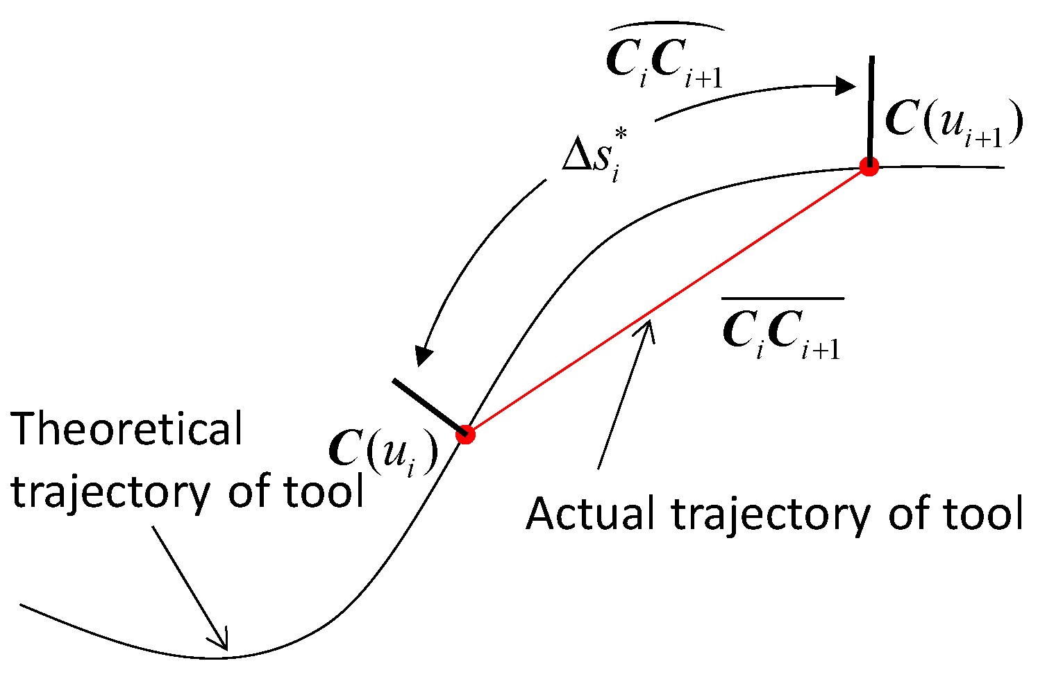
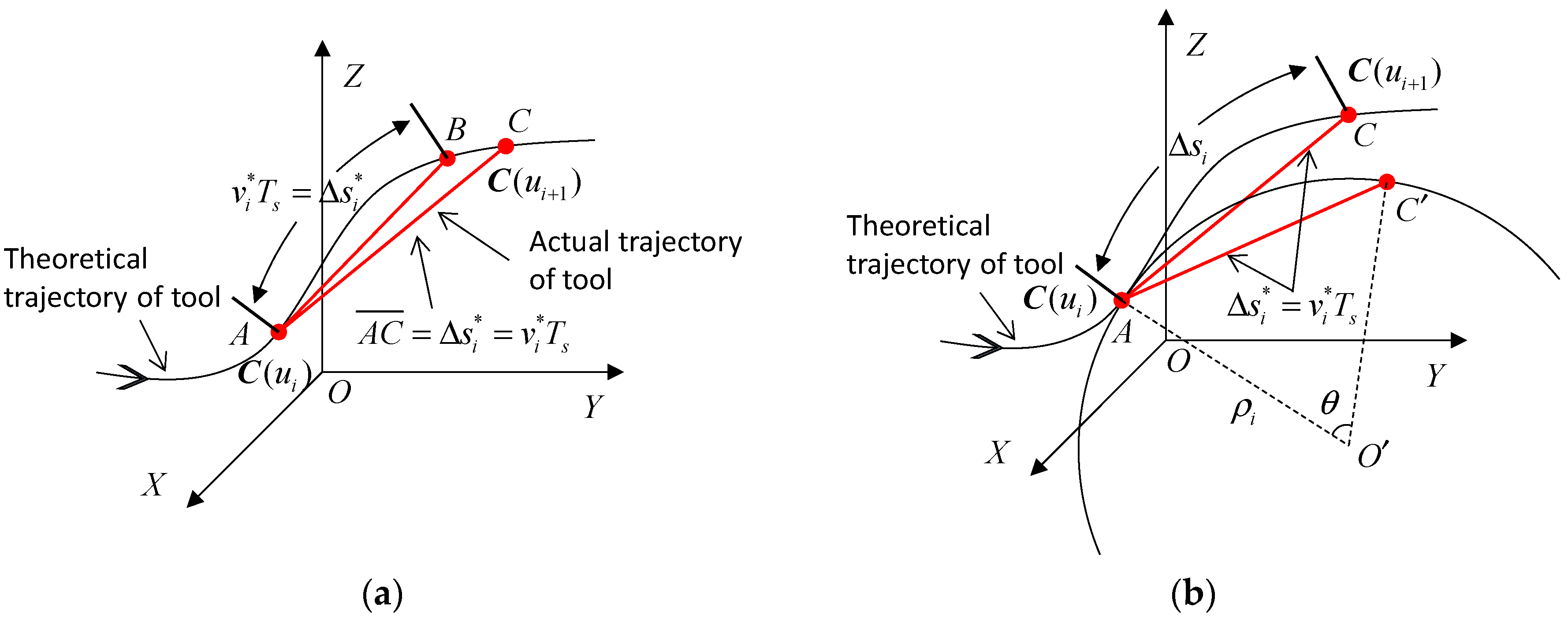
3.1. Compensation of Arc Length in the NURBS Tool Path Interpolation
3.2. Feedrate Fluctuation Restriction Based on the Newton Iteration Method
- Step 1:
- The arc length of the NURBS tool path at the current interpolation point is represented by si = sN × g(ui), where sN is the total arc length of the NURBS tool path.
- Step 2:
- The theoretical step length of the current interpolation cycle is calculated by ∆ = Ts.
- Step 3:
- Then, calculate the curvature radius of the NURBS tool path at the current interpolation point ui using the equation ρi = 1/ki = 1/φ(ui). The approximate interpolation arc length along the tool path is calculated by ∆si ≈ Ts + (Ts)3/24 using the arc length compensation method.
- Step 4:
- Then, calculate the next interpolation parameter point = f((si + ∆si)/sN) corresponding to the arc length increment ∆si.
- Step 5:
- Based on the initial value , the Newton iteration method is used to calculate the next interpolation point ui+1, at which the feedrate fluctuation is limited to a predetermined threshold εmax.
- Step 6:
- If ui+1 ≥ 1, the interpolation process terminates; otherwise, i = i+1, and go to step 1.
4. Implementations
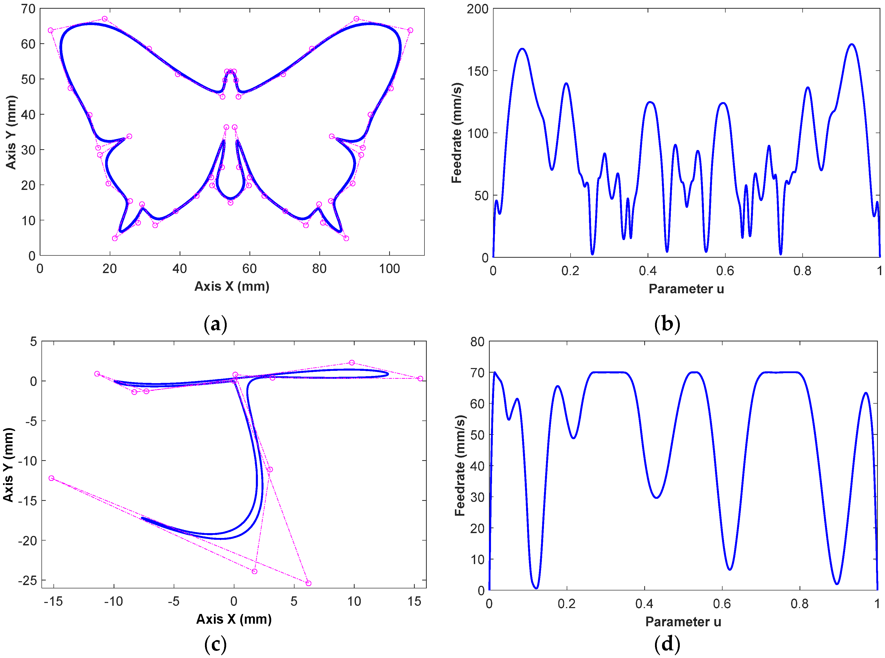
4.1. Case I
4.2. Case II
4.3. Case III
5. Conclusions
- (1)
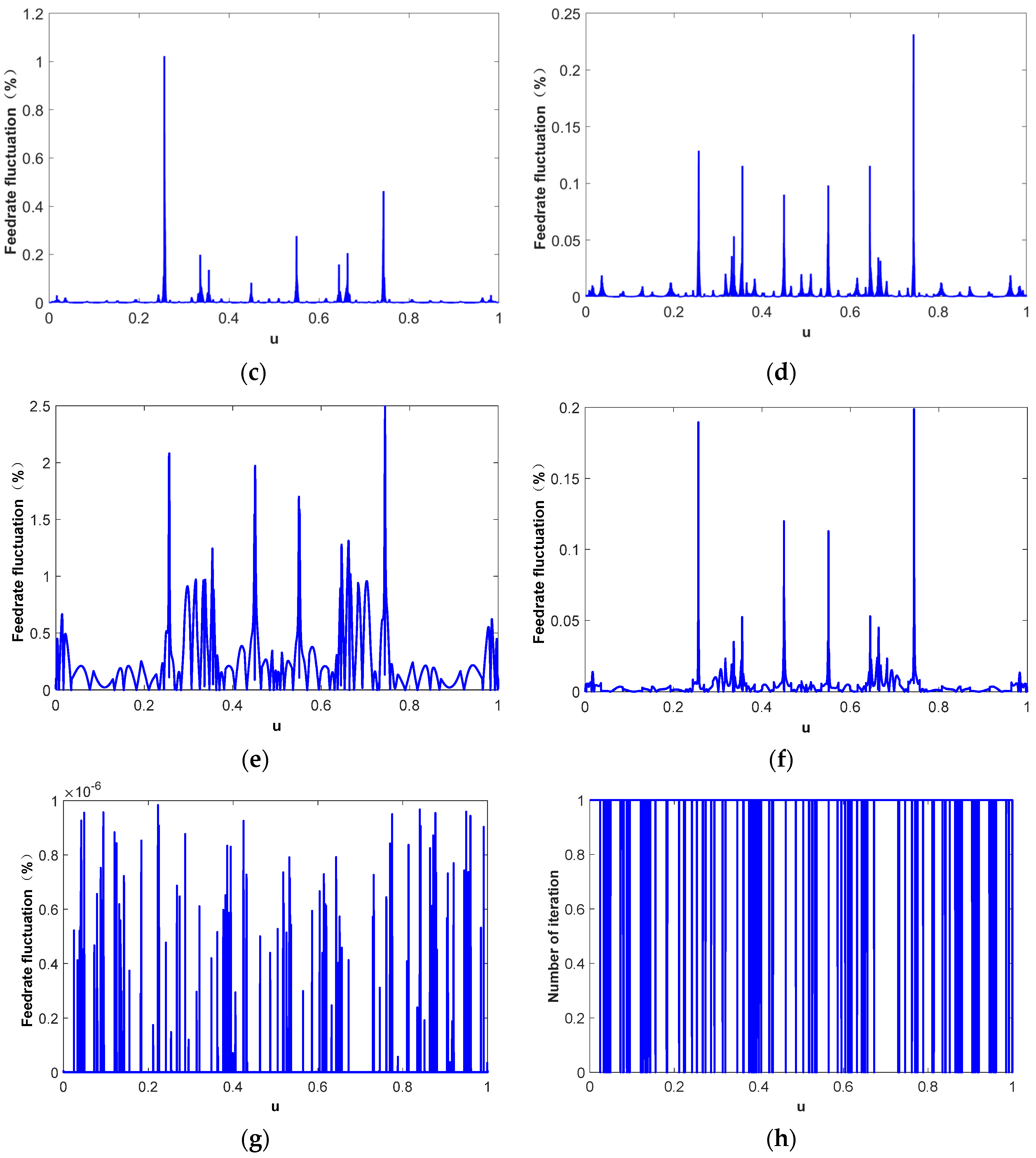
- An effective and computationally efficient arc length compensation method combined with Newton iteration is proposed to reduce the feedrate fluctuation.
- (2)
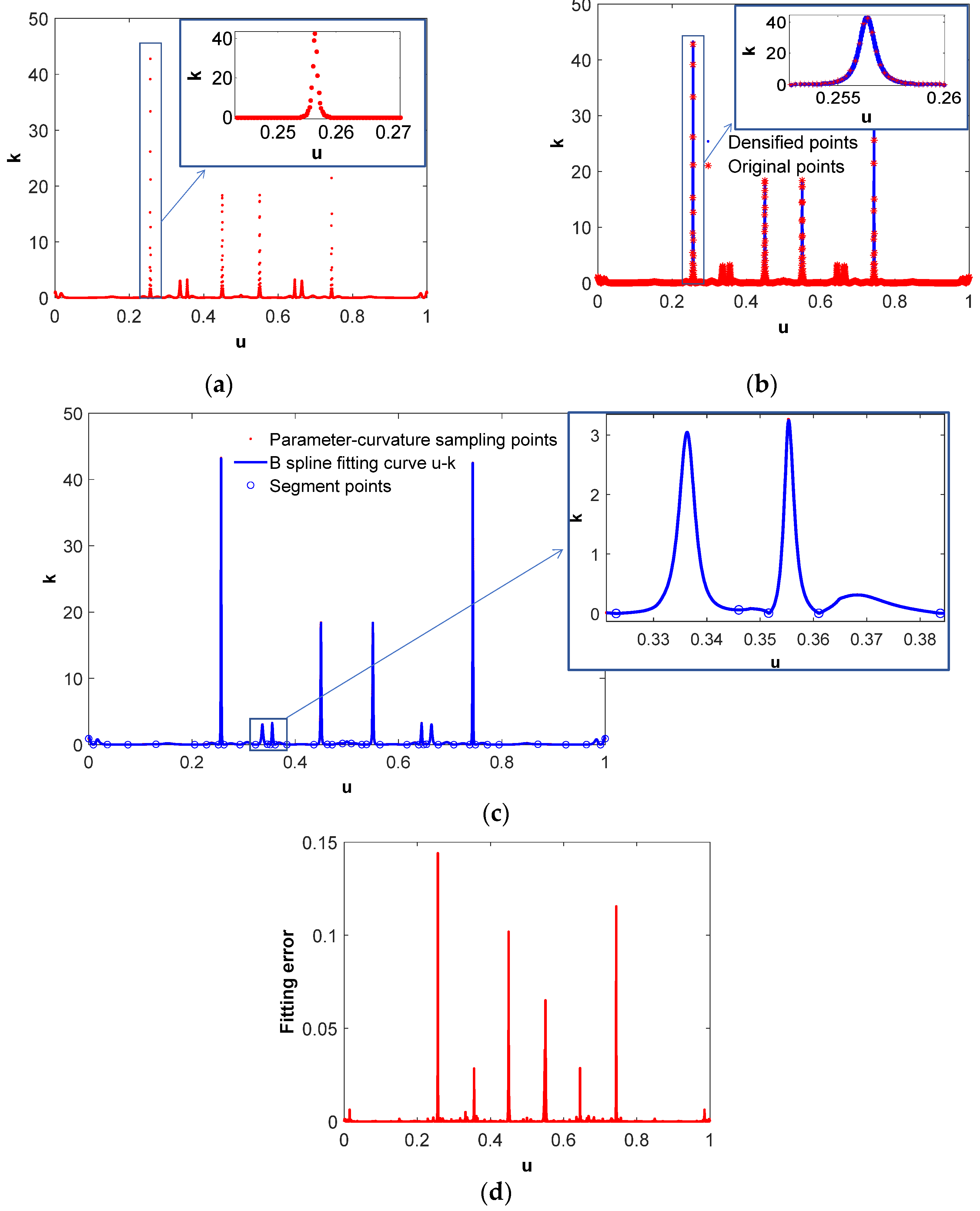
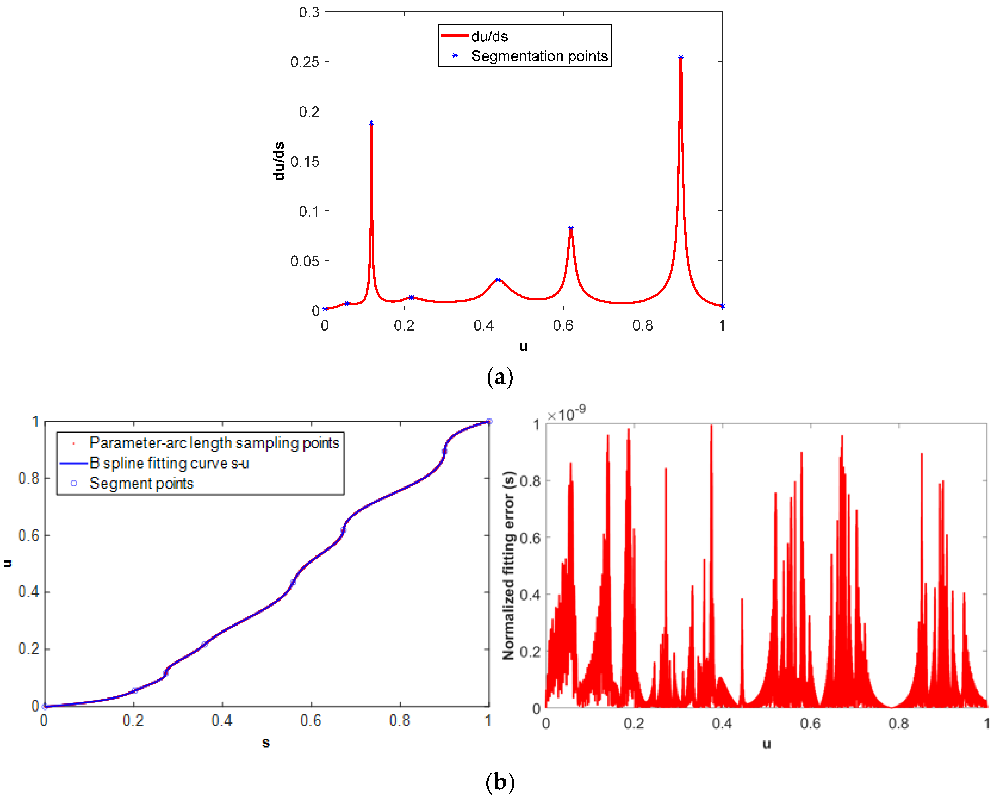
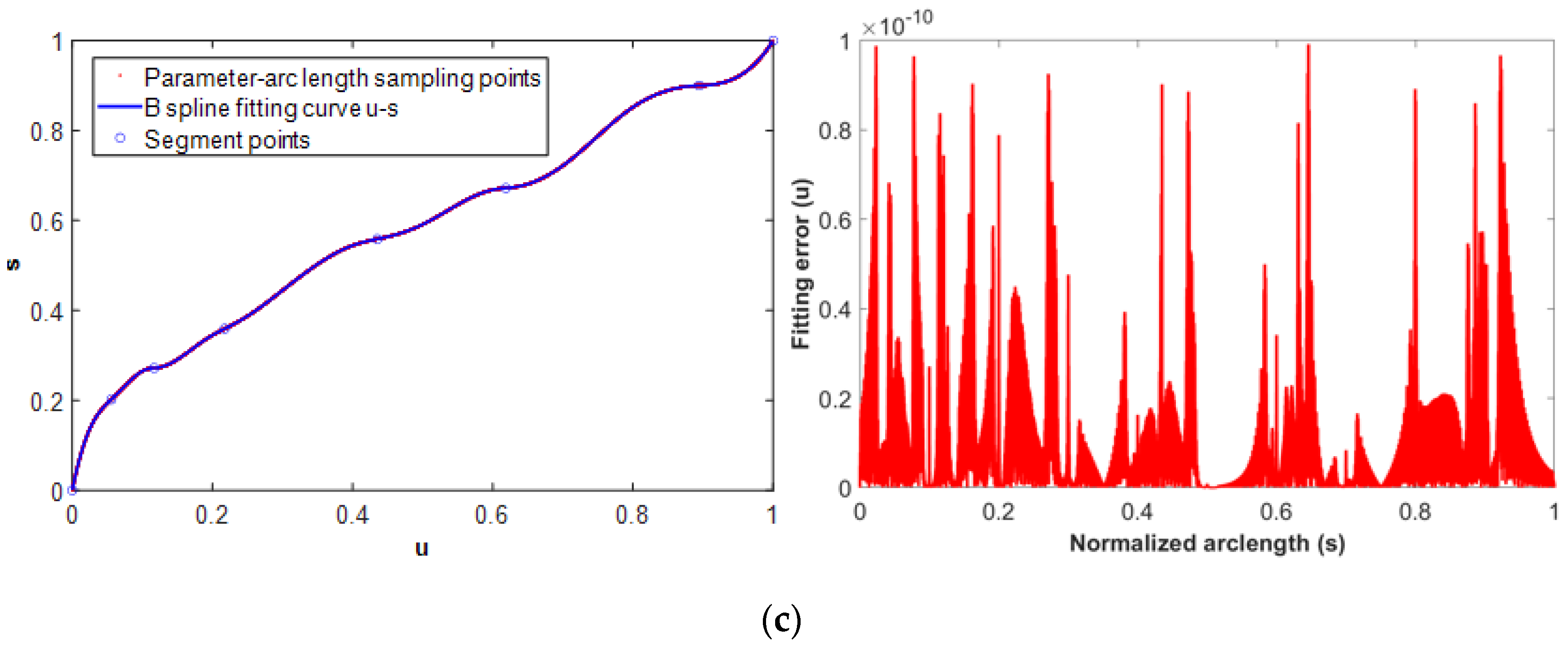
- The high-precision s-u-, u-s-, and u-k-segmented B-spline fitting method is employed to obtain the arc length increment corresponding to the parameter increment and the curvature of tool path at the interpolation points with a small calculation amount.
- (3)
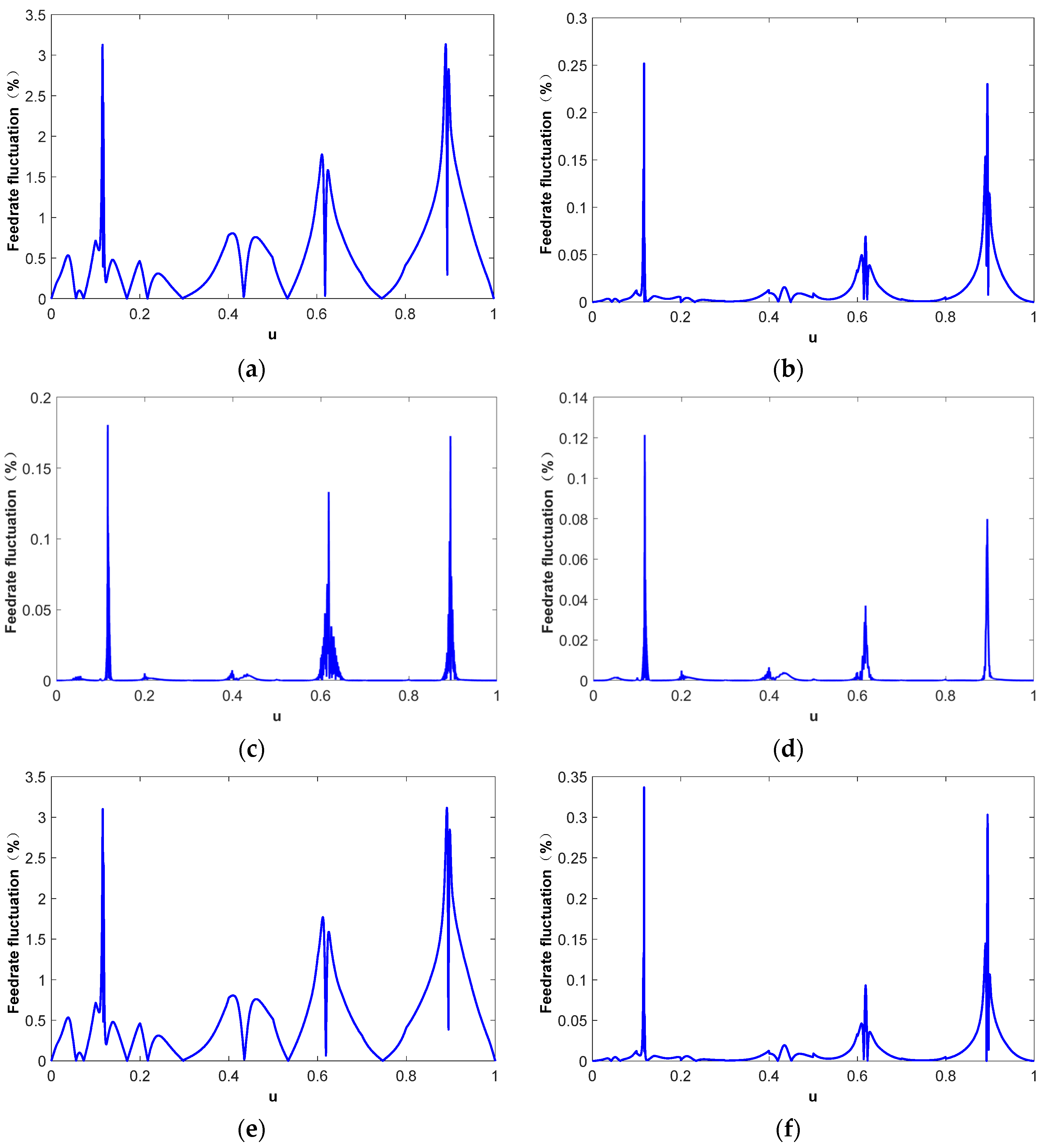
- A comparison with different parametric interpolation methods verifies the superiority of the proposed feedrate fluctuation restriction method.
- (4)
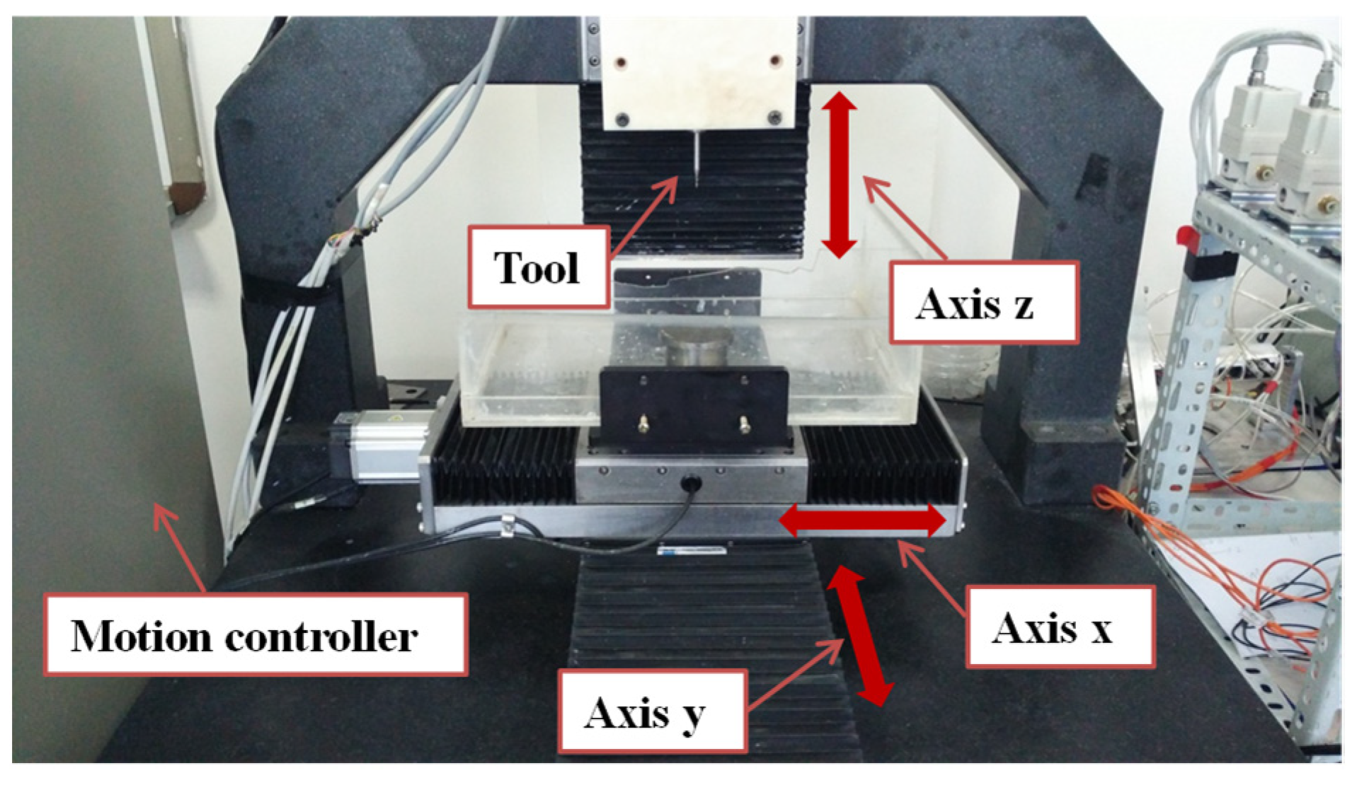
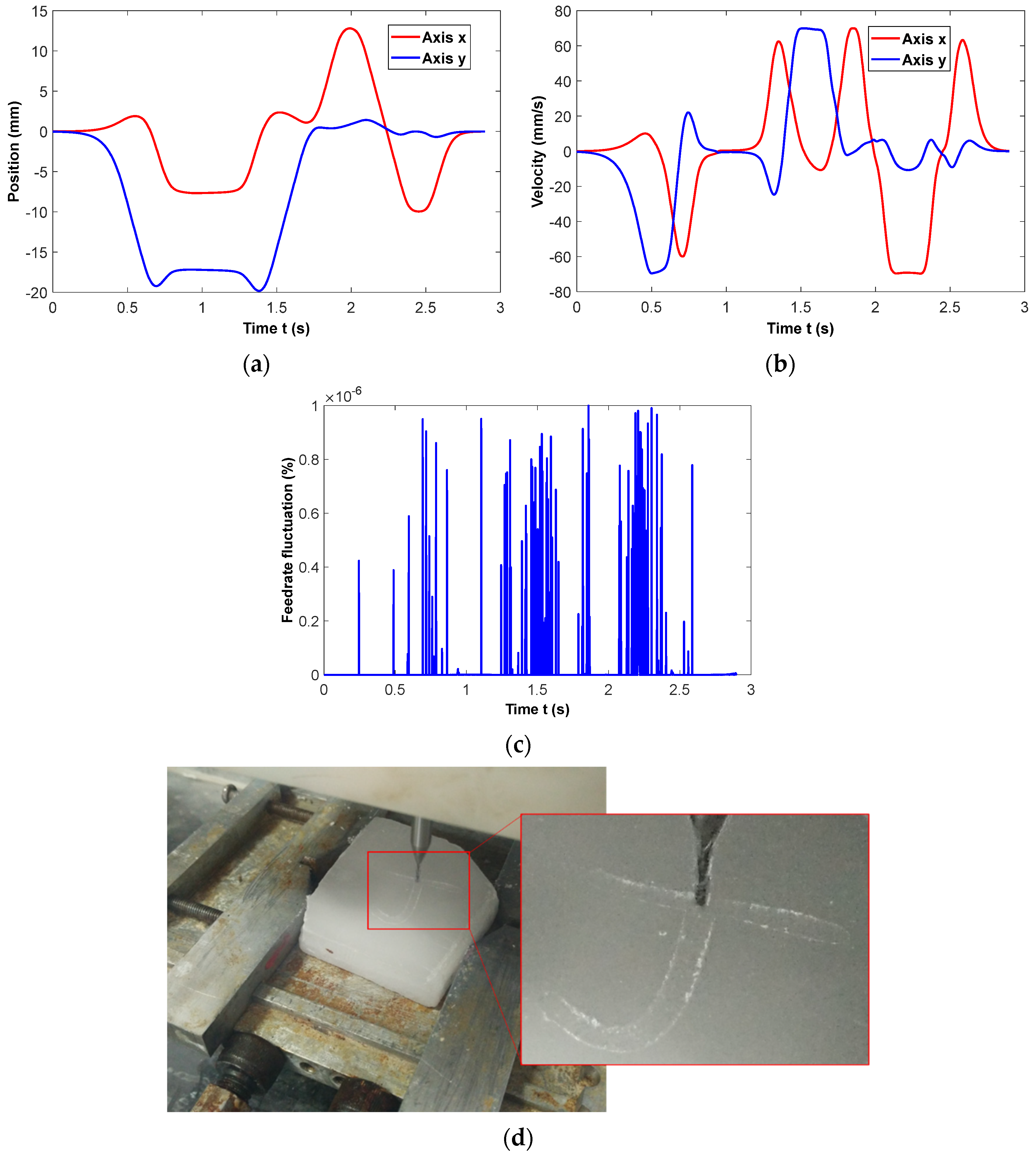
- The milling experiment results demonstrate that the effective restriction of feedrate fluctuation is conducive to obtain a smooth machining process.
Author Contributions
Funding
Data Availability Statement
Acknowledgments
Conflicts of Interest
Abbreviations
| CNC | Computer Numerical Control |
| NURBS | Non-Uniform Rational B-Splines |
| CTD | Co-lateral triangle deviation |
| ILF | Inverse arc length function |
| PMAC | Programmable multi-axes controller |
Appendix A
Appendix A.1. B-Spline Fitting for Parameter–Arc Length of NURBS Tool Path
- Arc Length Calculation of NURBS Tool Path
- B-spline Fitting on the Discrete Parameter–Arc Length Points for u-s and s-u Curves
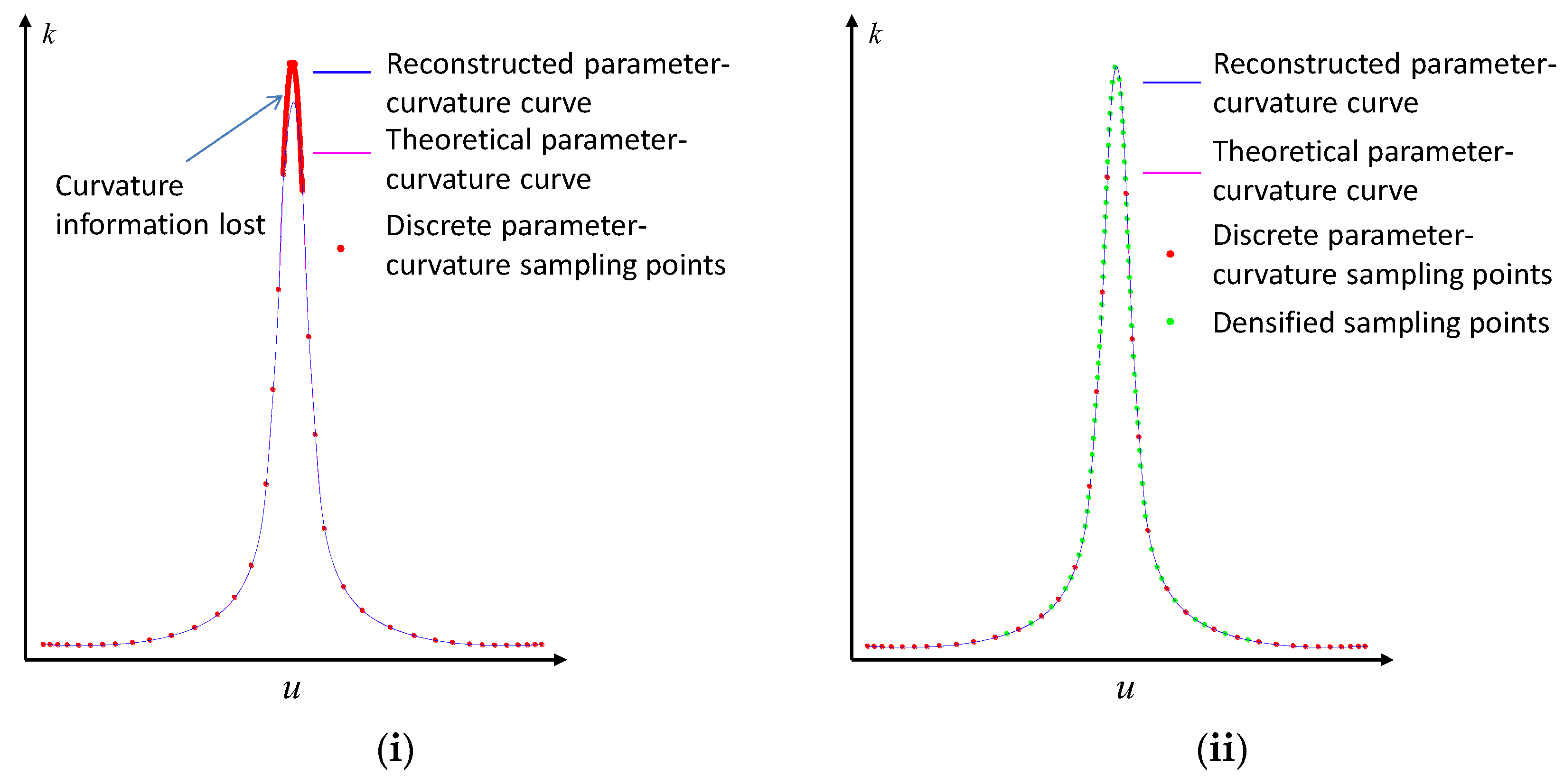
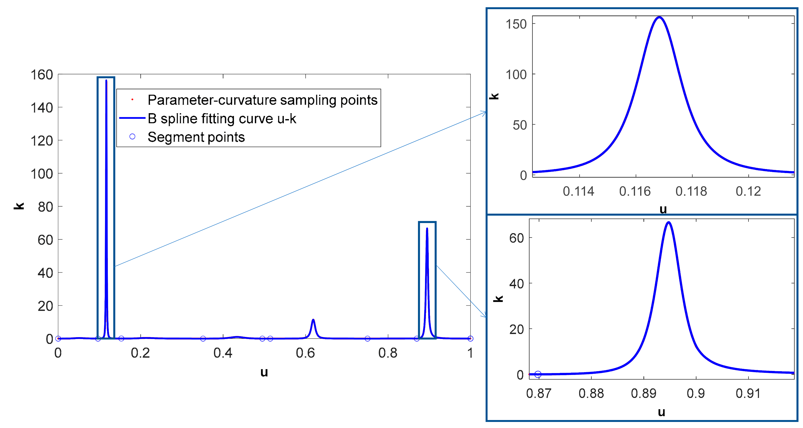
Appendix A.2. B-Spline Fitting for Parameter-Curvature of NURBS Tool Path
- Discrete Parameter-Curvature Points Sampling for NURBS Tool Path
References
- Wang, Y.; Zhou, T.; Zhou, J.; Li, M.; Liang, Z.; Wang, X. Precision milling of integrated turbine based on a non-contact on-machine measurement system. Nanomanufacturing Metrol. 2022, 5, 394–402. [Google Scholar]
- Yuan, Y.J.; Yu, K.K.; Zhang, C.; Chen, Q.; Yang, W.X. Generation of Textured Surfaces by Vibration-Assisted Ball-End Milling. Nanomanufacturing Metrol. 2023, 6, 19. [Google Scholar] [CrossRef]
- Liang, F.S.; Kang, C.W.; Lu, Z.Y.; Fang, F.Z. Iso-scallop tool path planning for triangular mesh surfaces in multi-axis machining. Robot. Comput. Integr. Manuf. 2021, 72, 102206. [Google Scholar]
- Li, C.; Wang, K.; Zakharov, O.; Cui, H.; Wu, M.; Zhao, T.; Yan, Y.; Geng, Y. Damage evolution mechanism and low-damage grinding technology of silicon carbide ceramics. Int. J. Extrem. Manuf. 2025, 7, 022015. [Google Scholar]
- Liang, F.S.; Yan, G.P.; Fang, F.Z. Global time-optimal B-spline feedrate scheduling for a two-turret multi-axis NC machine tool based on optimization with genetic algorithm. Robot. Comput. Integr. Manuf. 2022, 75, 102308. [Google Scholar] [CrossRef]
- Xu, J.T.; Zhang, D.Y.; Sun, Y.W. Kinematics performance oriented smoothing method to plan tool orientations for 5-axis ball-end CNC machining. Int. J. Mech. Sci. 2019, 157–158, 293–303. [Google Scholar]
- Yang, J.; Hu, Q.; Ding, H. A two-stage CNC interpolation algorithm for corner smoothing trajectories with geometric error and dynamics constraints. Procedia CIRP 2016, 56, 306–310. [Google Scholar]
- Bartoň, M.; Bizzarri, M.; Rist, F.; Sliusarenko, O.; Pottmann, H. Geometry and Tool Motion Planning for Curvature Adapted CNC Machining; ACM: New York, NY, USA, 2021. [Google Scholar]
- Dong, J.; Ferreira, P.M.; Stori, J.A. Feed-rate optimization with jerk constraints for generating minimum-time trajectories. Int. J. Mach. Tools Manuf. 2007, 47, 1941–1955. [Google Scholar]
- Heng, M.; Erkorkmaz, K. Design of a NURBS interpolator with minimal feed fluctuation and continuous feed modulation capability. Int. J. Mach. Tools Manuf. 2010, 50, 281–293. [Google Scholar]
- Huang, X.Y.; Zhao, F.; Tao, T.; Mei, X.S. A newly developed corner smoothing methodology based on clothoid splines for high speed machine tools. Robot. Comput. Integr. Manuf. 2021, 70, 102106. [Google Scholar]
- Liu, H.; Liu, Q.; Sun, P.P.; Liu, Q.T.; Yuan, S.M. A polynomial equation-based interpolation method of NURBS tool path with minimal feed fluctuation for high-quality machining. Int. J. Adv. Manuf. Technol. 2017, 90, 2751–2759. [Google Scholar] [CrossRef]
- Wang, T.Y.; Zhang, Y.B.; Dong, J.C.; Ke, R.J.; Ding, Y.Y. NURBS interpolator with adaptive smooth feedrate scheduling and minimal feedrate fluctuation. Int. J. Precis. Eng. Manuf. 2020, 21, 273–290. [Google Scholar] [CrossRef]
- Baek, D.K.; Yang, S.H.; Ko, T.J. Precision NURBS interpolator based on recursive characteristics of NURBS. Int. J. Adv. Manuf. Technol. 2013, 65, 403–410. [Google Scholar] [CrossRef]
- Hu, Y.F.; Jiang, X.; Huo, G.Y.; Su, C.; Li, H.X.; Zheng, Z.M. A novel method for calculating interpolation points of NURBS curves based on chord length-parameter ratio. Int. J. Adv. Manuf. Technol. 2023, 129, 2843–2860. [Google Scholar] [CrossRef]
- Jia, Z.Y.; Song, D.N.; Ma, J.W.; Hu, G.Q.; Su, W.W. A NURBS interpolator with constant speed at feedrate-sensitive regions under drive and contour-error constraints. Int. J. Mach. Tools Manuf. 2017, 116, 1–17. [Google Scholar] [CrossRef]
- Song, D.N.; Jia, Z.Y.; Ma, J.W.; Zhang, N.; Si, L.K. A precise direct parametric interpolation method for NURBS-toolpath generation. Int. J. Ind. Syst. Eng. 2019, 31, 278–286. [Google Scholar] [CrossRef]
- Xu, B.; Ding, Y.; Ji, W. An interpolation method based on adaptive smooth feedrate scheduling and parameter increment compensation for NURBS curve. ISA Trans. 2022, 128, 633–645. [Google Scholar] [CrossRef]
- Zhang, G.X.; Gao, J.; Zhang, L.Y.; Wang, X.D.; Luo, Y.H.; Chen, X. Generalised NURBS interpolator with nonlinear feedrate scheduling and interpolation error compensation. Int. J. Mach. Tools Manuf. 2022, 183, 103956. [Google Scholar] [CrossRef]
- Ni, H.P.; Zhang, C.R.; Chen, C.; Hu, T.L.; Liu, Y.N. A parametric interpolation method based on prediction and iterative compensation. Int. J. Adv. Robot. Syst. 2019, 16, 1729881419828188. [Google Scholar] [CrossRef]
- Jiang, J.L.; Lin, F.Y.; Zhang, Y.; Zhang, H.; Ye, P.Q. A real-time feedrate planning method and efficient interpolator with minimal feedrate fluctuation for parametric toolpath. IEEE Access 2019, 7, 112953–112962. [Google Scholar] [CrossRef]
- Chen, M.S.; Sun, Y.W. Contour error–bounded parametric interpolator with minimum feedrate fluctuation for five-axis CNC machine tools. Int. J. Adv. Manuf. Technol. 2019, 103, 567–584. [Google Scholar] [CrossRef]
- Nie, M.X.; Zhu, T.; Li, Y. NURBS interpolator with minimum feedrate fluctuation based on two-level parameter compensation. Sensors 2023, 23, 3789. [Google Scholar] [CrossRef] [PubMed]
- Erkorkmaz, K.; Altintas, Y. Quintic Spline Interpolation with Minimal Feed Fluctuation. Mach. Electron. 2007, 127, 523–531. [Google Scholar]
- Han, X.T.; Zhu, K.F.; Wang, X.B. A hash approach to refine CNC computation of arc length and parameter of NURBS with high efficiency and precision. Int. J. Precis. Eng. Manuf. 2024, 25, 1243–1256. [Google Scholar] [CrossRef]
- Lei, W.T.; Sung, M.P.; Lin, L.Y.; Huang, J.J. Fast real-time NURBS path interpolation for CNC machine tools. Int. J. Mach. Tools Manuf. 2007, 47, 1530–1541. [Google Scholar] [CrossRef]
- Liu, H.; Liu, Q.; Zhou, S.K.; Li, C.J.; Yuan, S.M. A NURBS interpolation method with minimal feedrate fluctuation for CNC machine tools. Int. J. Adv. Manuf. Technol. 2015, 78, 1241–1250. [Google Scholar] [CrossRef]
- Wu, J.C.; Zhou, H.C.; Tang, X.Q.; Chen, J.H. A NURBS interpolation algorithm with continuous feedrate. Int. J. Adv. Manuf. Technol. 2012, 59, 623–632. [Google Scholar] [CrossRef]
- Liu, M.; Huang, Y.; Yin, L.; Guo, J.W.; Shao, X.Y.; Zhang, G.J. Development and implementation of a NURBS interpolator with smooth feedrate scheduling for CNC machine tools. Int. J. Mach. Tools Manuf. 2014, 87, 1–15. [Google Scholar] [CrossRef]
- Jeong, S.Y.; Yun, J.C.; Park, P.G. Parametric interpolation using sampled data. Comput. Aided Des. 2006, 38, 39–47. [Google Scholar] [CrossRef]
- Lu, L.; Zhang, L.; Gu, Y.; Zhao, J. Fast parametric curve interpolation with minimal feedrate fluctuation by cubic B-spline. Proc. Inst. Mech. Eng. Part B J. Eng. Manuf. 2016, 232, 1642–1652. [Google Scholar] [CrossRef]
- Du, X.; Huang, J.; Zhu, L.M. A complete S-shape feed rate scheduling approach for NURBS interpolator. J. Comput. Des. Eng. 2015, 2, 206–217. [Google Scholar] [CrossRef]
- Zhang, Y.B.; Wang, T.Y.; Peng, P.; Dong, J.C.; Cao, L.B.; Tian, C. Feedrate blending method for five-axis linear tool path under geometric and kinematic constraints. Int. J. Mech. Sci. 2021, 195, 106262. [Google Scholar]
- Sun, S.J.; Zhao, P.; Zhang, T.; Li, B.B.; Yu, D. Smoothing interpolation of five-axis tool path with less feedrate fluctuation and higher computation efficiency. J. Manuf. Process. 2024, 109, 669–693. [Google Scholar] [CrossRef]
- Liang, F.S.; Zhao, J.; Ji, S.J. An iterative feed rate scheduling method with confined high-order constraints in parametric interpolation. Int. J. Adv. Manuf. Technol. 2017, 92, 2001–2015. [Google Scholar] [CrossRef]
- Min, K.; Sun, Y.; Lee, C.-H.; Hu, P.; He, S. An improved b-spline fitting method with arc-length parameterization, g 2-continuous blending, and quality refinement. Int. J. Precis. Eng. Manuf. 2019, 20, 1939–1955. [Google Scholar]
- Yang, Z.; Shen, L.-Y.; Yuan, C.-M.; Gao, X.-S. Curve fitting and optimal interpolation for CNC machining under confined error using quadratic B-splines. Comput. Aided Des. 2015, 66, 62–72. [Google Scholar]
- Liang, F.S.; Zhao, J.; Ji, S.J.; Fan, C.; Zhang, B. A novel knot selection method for the error-bounded B-spline curve fitting of sampling points in the measuring process. Meas. Sci. Technol. 2017, 28, 14. [Google Scholar]


| Parametric Interpolation Methods | Feedrate Fluctuation | ||
|---|---|---|---|
| Maximum | Mean | MSE | |
| First-order Taylor expansion | 2.47 | 0.345 | 0.348 |
| Second-order Taylor expansion | 0.149 | 5.81 × 10⁻³ | 9.75 × 10⁻³ |
| s-u fitting curve | 4.83 × 10⁻² | 7.74 × 10⁻⁴ | 2.95 × 10⁻³ |
| s-u fitting curve and arc length compensation | 5.32 × 10⁻³ | 1.77 × 10⁻⁴ | 3.12 × 10⁻⁴ |
| Arc length compensation-based first-order Taylor expansion | 2.49 | 0.345 | 0.348 |
| Arc length compensation-based second-order Taylor expansion | 0.199 | 6.01 × 10⁻³ | 1.13 × 10⁻² |
| Newton iteration method based on the initial value derived from s-u fitting curve and arc length compensation (threshold 10−6%) | 9.83 × 10⁻⁷ | 1.32 × 10⁻⁸ | 8.99 × 10⁻⁸ |
| Parametric Interpolation Methods | Feedrate Fluctuation | ||
|---|---|---|---|
| Maximum | Mean | MSE | |
| First-order Taylor expansion | 3.13 | 0.408 | 0.507 |
| Second-order Taylor expansion | 0.252 | 8.42 × 10⁻³ | 2.04 × 10⁻² |
| s-u fitting curve | 8.59 × 10⁻² | 9.07 × 10⁻⁴ | 5.36 × 10⁻³ |
| s-u fitting curve and arc length compensation | 9.39 × 10⁻³ | 1.39 × 10⁻⁴ | 5.62 × 10⁻⁴ |
| Arc length compensation-based first-order Taylor expansion | 3.116 | 0.408 | 0.507 |
| Arc length compensation-based second-order Taylor expansion | 0.337 | 8.61 × 10⁻³ | 2.26 × 10⁻² |
| Newton iteration method based on the initial value derived from s-u fitting curve and arc length compensation (threshold 10−6%) | 9.99 × 10⁻⁷ | 2.25 × 10⁻⁸ | 1.19 × 10⁻⁷ |
Disclaimer/Publisher’s Note: The statements, opinions and data contained in all publications are solely those of the individual author(s) and contributor(s) and not of MDPI and/or the editor(s). MDPI and/or the editor(s) disclaim responsibility for any injury to people or property resulting from any ideas, methods, instructions or products referred to in the content. |
© 2025 by the authors. Licensee MDPI, Basel, Switzerland. This article is an open access article distributed under the terms and conditions of the Creative Commons Attribution (CC BY) license (https://creativecommons.org/licenses/by/4.0/).
Share and Cite
Liu, X.; Yu, P.; Chen, H.; Peng, B.; Wang, Z.; Liang, F. Feedrate Fluctuation Minimization for NURBS Tool Path Interpolation Based on Arc Length Compensation and Iteration. Micromachines 2025, 16, 402. https://doi.org/10.3390/mi16040402
Liu X, Yu P, Chen H, Peng B, Wang Z, Liang F. Feedrate Fluctuation Minimization for NURBS Tool Path Interpolation Based on Arc Length Compensation and Iteration. Micromachines. 2025; 16(4):402. https://doi.org/10.3390/mi16040402
Chicago/Turabian StyleLiu, Xing, Pengxin Yu, Haiduo Chen, Bihui Peng, Zhao Wang, and Fusheng Liang. 2025. "Feedrate Fluctuation Minimization for NURBS Tool Path Interpolation Based on Arc Length Compensation and Iteration" Micromachines 16, no. 4: 402. https://doi.org/10.3390/mi16040402
APA StyleLiu, X., Yu, P., Chen, H., Peng, B., Wang, Z., & Liang, F. (2025). Feedrate Fluctuation Minimization for NURBS Tool Path Interpolation Based on Arc Length Compensation and Iteration. Micromachines, 16(4), 402. https://doi.org/10.3390/mi16040402