Abstract
Emerging applications including advanced industrial manufacturing, cutting-edge scientific research and medical equipment demand AlGaN/GaN HEMTs possessing both high-frequency and high-voltage characteristics. However, a persistent trade-off remains between the frequency characteristics and breakdown characteristics of these devices. In this study, we employed localized electric field tailoring (LEFT) by introducing materials with different dielectric constants to construct a non-uniform composite gate dielectric layer, aiming to balance the breakdown voltage and cut-off frequency of the device. Device models were developed using APSYS-2018 software and their reliability was experimentally validated. Research data indicates that, compared to traditional uniform high-k (typically with dielectric constants k > 10, such as HfO2 and HfZrO) gate dielectrics, the non-uniform composite gate dielectric structure demonstrates superior transconductance, saturation current density and cut-off frequency, with minimal degradation in breakdown voltage. Specifically, relative to HfO2 and HfZrO uniform devices, the Al2O3/HfO2 and Al2O3/HfZrO non-uniform HEMTs achieved 20.0% and 35.2% increases in cut-off frequency, respectively. Meanwhile, breakdown voltage remained above 97% of their uniform counterparts, saturation current density and transconductance increased by approximately 5%. Therefore, this non-uniform composite gate dielectric layer structure of AlGaN/GaN HEMT with LEFT holds great potential for industrial plasma generators, magnetic resonance imaging systems and biomedical radiofrequency hyperthermia devices.
1. Introduction
AlGaN/GaN heterojunction exhibits stronger spontaneous and piezoelectric polarization effects [1,2] compared to other III-V heterojunctions, generating a two-dimensional electron gas (2DEG) [3] at the interface. Consequently, AlGaN/GaN HEMTs demonstrate superior electrical characteristics, including high carrier concentration, mobility, and breakdown field [4,5,6], coupled with low on-resistance [7] and high switching speed [8]. Given the aforementioned advantages of AlGaN/GaN HEMTs and the inefficiency of Si-based devices at MHz frequencies, HEMTs integrating both high-frequency and high-voltage capabilities therefore demonstrate application prospects in emerging fields, including industrial plasma generators (e.g., PECVD devices), medical and scientific equipment (e.g., magnetic resonance imaging systems), and biomedical radiofrequency hyperthermia (e.g., 13.56 MHz tumor ablation systems).
However, the high-frequency performance and voltage withstand characteristics of AlGaN/GaN HEMTs are inherently trade-offs, posing significant challenges for co-optimization. Current breakdown voltage enhancement strategies include gate-drain spacing extension [9], gate lengthening [10], and MOS-structure integration [11]. Since dimensional scaling substantially increases on-resistance (Ron), degrading power density and high-frequency characteristics, we implement MOS architectures for balanced performance. This approach deposits high-k gate dielectrics between metal and semiconductor interfaces [12], including hafnium-based oxides (e.g., HfO2 [13], HfSiOx [14], HfZrOx [15]), aluminum-based oxides (Al2O3 [16]), and zirconium-based oxides (ZrO2 [17]). In this context, “high-k” refers to dielectric materials with relative permittivity significantly higher than that of SiO2 (k ≈ 3.9), typically exceeding 10, such as HfO2 (k ≈ 25) and HfZrO (k ≈ 30). Al2O3 (k ≈ 9) is considered a moderate-to-high-k material. Although improving breakdown robustness, these high-k layers inevitably impose cut-off frequency penalties [18]. Notably, breakdown is typically localized, whereas frequency characteristics are uniform and holistic. This difference arises from non-uniform electric field distribution within the device: electric field concentration at the gate edge amplifies impact ionization, ultimately triggering localized avalanche breakdown. Conversely, the homogeneity of frequency characteristics relies on holistic carrier transport throughout the channel, which is governed by the statistically averaged properties of carriers (e.g., density, mobility, and velocity distribution) rather than local electric field peaks. Therefore, we propose localized reinforcement to enhance the device’s cut-off frequency while maintaining high breakdown voltage. Localized reinforcement refers to depositing the high-k dielectric layer at the drain-side gate edge where electric field crowding induces breakdown, while lower-k materials occupy low-field regions to minimize equivalent gate capacitance.
This study implements localized electric field tailoring (LEFT) through non-uniform composite gate dielectrics. High-k material at the gate-drain side enhances breakdown voltage, while lower-k material on the gate-source side improves cut-off frequency. This structure balances breakdown and frequency characteristics. Conventional uniform Al2O3 devices were fabricated for experimental validation, confirming model reliability. Additional devices incorporating HfO2 and HfZrO were systematically characterized. Compared to uniform high-k gate dielectrics, the proposed non-uniform composite structure effectively optimized electric field distribution while maintaining comparable breakdown voltage. More impressively, the cut-off frequency was significantly enhanced. These results demonstrate LEFT-enabled non-uniform gate dielectrics’ strong potential for practical applications.
2. Materials and Methods
Device models were developed using the APSYS platform, and corresponding devices were fabricated. Figure 1a illustrates the cross-sectional structure of the simulated device, with key geometric parameters provided in Table 1.
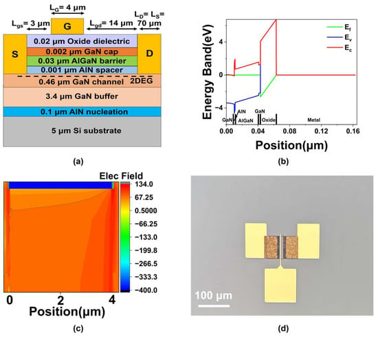
Figure 1.
(a) The cross-section schematic of the AlGaN/GaN MOS-HEMT. (b) Band diagram of the MOS structure. (c) Two-dimensional electric field distribution under the gate in Al2O3 MOS-HEMT. (d) A micrograph of the Al2O3 MOS-HEMT.

Table 1.
Specific geometric parameters of the AlGaN/GaN MOS-HEMT.
After device modeling, appropriate physical models and simulation parameters were applied to predict device behavior. Self-heating effects were simulated via an integrated thermal module, and breakdown characteristics were evaluated using an impact ionization model. The AlGaN/GaN heterojunction interface was treated with a polarization charge model. Besides the aforementioned physical models, the modified transferred-electron mobility model was also employed to accurately describe the current transport process. This model effectively hybridizes MTE and Canali models [19], as shown in Equations (1)–(3):
where V(E) denotes the electron drift velocity, while VMTE(E) and VC(E) represent the electron drift velocities described by the MTE and Canali models, respectively. As shown, Equation (1) reduces to the MTE model when x = 1, and approaches the Canali model as x tends to 0. For the intermediate case of x = 0.5, Equation (1) incorporates an equal weighting of 50% from both the MTE and Canali models. The function F(E) is to imitate the kink in the low-field region, Vsat denotes the saturation velocity, E represents the electric field, EMT is a fixed field value, μlow is the low-field mobility, and βT and βC correspond to the values of parameters beta_mte and beta_n in the model.
Another important effect is the impurity dependence of the low field mobility, as shown in Equations (4) and (5):
where μ0n and μ0p are the low-field electron and hole mobilities, respectively; μ1n and μ1p are the carrier mobilities at high impurity concentration; μ2n and μ2p denote the carrier mobilities at low impurity concentration; ND and NA are the donor and acceptor concentrations; ΣjNtj is the total density of trap/defect levels summed over all considered trap types j; Nrn and Nrp are the empirical reference impurity concentrations; and αn and αp are empirical fitting exponents that determine how rapidly the mobility transitions with increasing total charged/neutral defect concentration for electrons and holes.
A drift-diffusion model was used to govern the electrical behavior of the device. Fermi–Dirac statistics were employed to accurately calculate the carrier distribution of the high-concentration 2DEG, as shown in Equations (6)–(8):
where n and p are the electron and hole concentrations; NC and NV are the effective density of states in the conduction and valence bands; Efn and Efp are the quasi-Fermi levels for electrons and holes; EC and EV are the conduction and valence band edges; k is the Boltzmann constant; T is the absolute temperature; F1/2 is the Fermi integral of order one-half; and ξ(x) is a correction function used in the approximate form of the Fermi integral.
The Shockley–Read–Hall recombination model was utilized to simulate the carrier recombination process via defect levels in the material:
where and denote the electron and hole recombination rates via the j-th trap level; cnj and cpj are the capture coefficients for electrons and holes; n and p represent the free electron and hole concentrations; n1j and p1j are the carrier concentrations when the trap level equals the Fermi level; Ntj is the trap density; and J is the trap occupancy probability.
The capture coefficients can be further expressed as follows:
where σnj and σpj are the capture cross-sections for electrons and holes; and are the average thermal velocities of electrons and holes; mn and mp represent the effective masses of electrons and holes. The trap or recombination center is completely specified by its density Ntj, capture cross-sections σnj and σpj, and energy level Etj. The numerical values of the relevant physical parameters in Equations (1)–(12) are presented in Table 2. Figure 1b shows the energy band diagram of the MOS structure in Al2O3 MOS-HEMT. The conduction band of GaN on the left side contacts the Fermi level due to strong spontaneous and piezoelectric polarization effects. These effects lead to a high electron concentration in the channel layer, driving it into a degenerate state and forming a conductive channel. A two-dimensional electron gas is present at the interface between the Fermi level and the triangular quantum well. Figure 1c shows the two-dimensional electric field distribution under the gate in Al2O3 MOS-HEMT. The electric field is uniformly distributed, and the scale is calculated based on the actual electric field value of the formula 20log10.

Table 2.
Relevant physical parameters in Equations (1)–(12).
To validate the simulation model, conventional Al2O3 gate dielectric HEMTs were fabricated. The process began with mesa isolation by ICP etching using a Cl2/BCl3/Ar mixture (10/25/5 sccm). Source and drain electrodes were formed via electron-beam deposition of Ti/Al/Ni/Au (20/120/45/55 nm), followed by rapid thermal annealing at 850 °C for 30 s in N2 to achieve ohmic contacts. A 20 nm Al2O3 gate dielectric was deposited by ALD at 160 °C, and Ni/Au (80/50 nm) was evaporated to form the Schottky gate. A micrograph of the completed Al2O3 MOS-HEMT is shown in Figure 1d.
3. Results
3.1. Matching Simulated and Measured Data for the MOS-HEMT
Following fabrication, the DC output performance and transfer characteristics of the devices were characterized using a semiconductor analyzer and compared with simulation data for accuracy validation. As shown in Figure 2a, the measured and simulated maximum drain current density (Ids,max) values were 292.6 and 290.6 mA/mm, respectively, representing a difference of 0.7%. Figure 2b presents the transfer characteristics, with maximum transconductance (gm,max) values of 65.32 and 65.12 mS/mm, and threshold voltage (Vth) values of −4.80 and −4.77 V, showing a 0.3% and 0.6% discrepancy, respectively. To quantitatively verify the simulation accuracy, Table 3 compares the electrical characteristics extracted from the simulation and experiment, showing excellent consistency with deviations below 1%. These results demonstrate good agreement between measurement and simulation, confirming the reliability of the models.
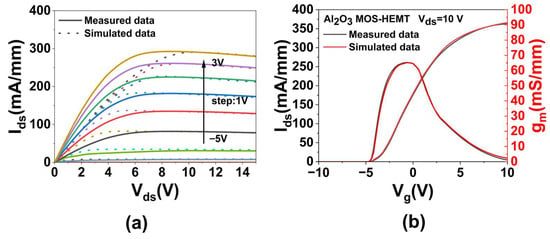
Figure 2.
Measured and simulated results of the Al2O3 MOS-HEMT: (a) DC output performance, (b) transfer characteristics.

Table 3.
Comparison between simulated and measured characteristics.
3.2. Mechanism of Localized Electric Field Tailoring by Non-Uniform Composite Gate Dielectrics
The schematic diagram of the non-uniform composite gate dielectric structure and the electric field distribution of Al2O3, HfO2, and Al2O3/HfO2 MOS-HEMTs are shown in Figure 3. Figure 3a presents the schematic of the non-uniform composite gate structure, incorporating high-k dielectrics (e.g., HfO2 and HfZrO) on the gate-drain side and a lower-k dielectric (e.g., Al2O3) on the gate-source side. Figure 3b displays the two-dimensional electric field distribution under the gate in the Al2O3/HfO2 MOS-HEMT, showing a peak at the 2 μm interface between the two dielectrics. Correspondingly, Figure 3c illustrates the transverse electric field profiles under the gate for Al2O3, HfO2, and Al2O3/HfO2 MOS-HEMTs. While the fields are uniform in the single-dielectric devices, a peak occurs at the dielectric interface in the composite structure, consistent with the observation in Figure 3b. This field discontinuity arises from the permittivity difference between HfO2 and Al2O3; the potential is continuous in the direction perpendicular to the interface, leading to a discontinuous jump in electric field strength. According to Gauss’s law, the electric fields perpendicular to the interface satisfy [20]
where ε1 and ε2 denote the dielectric constants of HfO2 and Al2O3, respectively, and E1 and E2 are the corresponding perpendicular electric fields. This field jump introduces a transverse electric field peak, enabling LEFT via regional control of dielectric constants. Figure 3d compares the transverse electric field at the drain-side gate edge for the three configurations, with values of 4.33, 4.30, and 4.24 MV/cm, respectively. The reduced field in the composite structure alleviates drain-edge field crowding and suppresses the hot electron effect, thereby enhancing reliability.
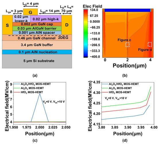
Figure 3.
(a) The schematic of the non-uniform composite gate dielectric structure. (b) Two-dimensional electric field distribution under the gate in Al2O3/HfO2 MOS-HEMT. The transverse electric field distribution in the channel (c) directly under the gate dielectric layer, (d) at the drain-side gate edge of Al2O3, HfO2, and Al2O3/HfO2 MOS-HEMTs.
3.3. Analysis of Simulation Results
The DC output characteristics of the MOS-HEMTs are shown in Figure 4. As shown in Figure 4a, the Al2O3 MOS-HEMT operates under a gate voltage ranging from −5 V to 3 V and achieves an Ids,max of 291 mA/mm. Beyond the saturation region, a discernible current reduction occurs, attributed to self-heating that elevates the heterojunction temperature and degrades output performance [21]. In contrast, the HfO2 MOS-HEMT (Figure 4b) is biased from −1 V to 6 V due to its higher Vth and positive bias stability, delivering an Ids,max of 354 mA/mm without significant current decrease. This represents a 22% improvement over the Al2O3 device, resulting from the higher dielectric constant of HfO2, which reduces the depletion region width and source–drain resistance, thereby enhancing channel conductivity [22]. Moreover, analysis based on interface and trap models indicates that the increased permittivity also mitigates surface scattering and carrier trapping [23] at the metal/AlGaN junction, which in turn increases channel carrier concentration [24]. Figure 4c shows the Al2O3/HfO2 MOS-HEMT, gated from −2 V to 5 V with Vth and positive bias stability intermediate between the single-dielectric devices. It exhibits an Ids,max of 371 mA/mm and minimal current degradation. The improved current stability in both HfO2 and Al2O3/HfO2 stems from the stronger electric field shielding under the gate, which reduces surface field intensity [25] and suppresses dynamic charge trapping/detrapping. The high-k dielectric also alleviates self-heating, enhancing reliability [26]. Finally, as summarized in Figure 4d, the simulated Ids,max of nine devices confirms that composite gate dielectrics achieve better performance compared to uniform higher-k layers, demonstrating that non-uniform composite gate dielectric devices with LEFT can deliver enhanced output characteristics.
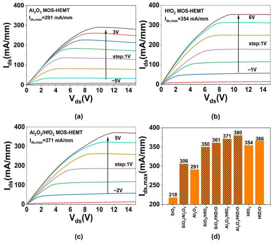
Figure 4.
The DC output performances (Ids-Vds) of the (a) Al2O3, (b) HfO2, (c) Al2O3/HfO2 MOS-HEMT. (d) The Ids,max of all the devices.
Figure 5a presents the transfer characteristics of the Al2O3 MOS-HEMT at Vds = 10 V and Vg swept from −10 V to 10 V, yielding a gm,max of 65.1 mS/mm and a Vth of −4.77 V. For the HfO2 MOS-HEMT (Figure 5b), gm,max reaches 74.5 mS/mm and Vth is −0.85 V. The 14.4% improvement in gm,max is attributed to the higher dielectric constant, which enhances gate control capability [27,28]. The positive shift in Vth also results from the increased permittivity [29]. As shown in Figure 5c, the Al2O3/HfO2 MOS-HEMT achieves a gm,max of 78.7 mS/mm and Vth of −1.96 V. The further 5.6% increase in gm,max over the HfO2 MOS-HEMT arises from LEFT, which optimizes field distribution and improves electron transport efficiency. The negative Vth shift relative to the HfO2 device is due to the reduced unit-area gate capacitance caused by the incorporation of the lower-k material. Based on the parallel-plate capacitance formula [30]:
where C represents the gate capacitance, ε denotes the absolute permittivity of dielectric layer (ε = ε0εr), S is the gate area, k is the Coulomb’s constant, and d represents the thickness of the gate dielectric layer. The threshold voltage can be expressed as follows [31]:
where VT represents the threshold voltage, εs denotes the semiconductor permittivity, q is the elementary charge, NA is the acceptor concentration, ψB is the bulk potential, and C0 is the unit-area gate capacitance derived from Equation (14). The numerical values of the relevant physical parameters in Equations (14) and (15) are presented in Table 4. As the gate capacitance decreases, the absolute value of Vth increases accordingly. Figure 5d,e summarize Vth and gm,max across nine devices. The composite dielectric devices exhibit slightly higher gm,max than their uniform high-k counterparts, consistent with previous trends. Figure 5f compares the gate voltage swing (GVS), defined as the Vg variation range where gm,max remains within 90% of its peak. GVS generally decreases with increasing dielectric constant, though composite dielectrics show improved GVS over uniform high-k layers. A higher GVS indicates enhanced linearity, which helps reduce phase noise, intermodulation distortion, and extends dynamic range in practical applications [32].
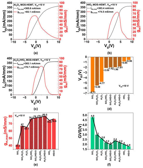
Figure 5.
The transfer characteristics of (a) Al2O3, (b) HfO2 and (c) Al2O3/HfO2 MOS-HEMT. The (d) Vth, (e) gm,max and (f) GVS values of all devices.

Table 4.
Representative physical parameters in Equations (14) and (15).
The breakdown voltage (Vbd) is defined as the Vds at which Vbd exceeds 1 mA/mm while Vg is held at −7 V to maintain the off-state. Figure 6a shows the Vbd of four uniform gate dielectric devices. With increasing dielectric constant, Vbd rises significantly [33]. Similarly, Figure 6b presents Vbd for five composite dielectric devices, where Vbd also increases with equivalent permittivity. Figure 6c compares Vbd among Al2O3, HfO2, and Al2O3/HfO2 MOS-HEMTs. The Al2O3/HfO2 MOS-HEMT exhibits Vbd nearly identical to the HfO2 device, with only a 1.7% reduction, attributable to non-uniform field distribution leading to localized breakdown near the gate-drain side [34], rather than uniform breakdown. Figure 6d summarizes Vbd across all nine devices. Vbd increases consistently with dielectric constant from left to right. Moreover, the breakdown voltages of SiO2/Al2O3, Al2O3/HfO2, and Al2O3/HfZrO MOS-HEMTs closely match those of their uniform higher-k counterparts, confirming the feasibility and effectiveness of LEFT in improving breakdown performance and device reliability.
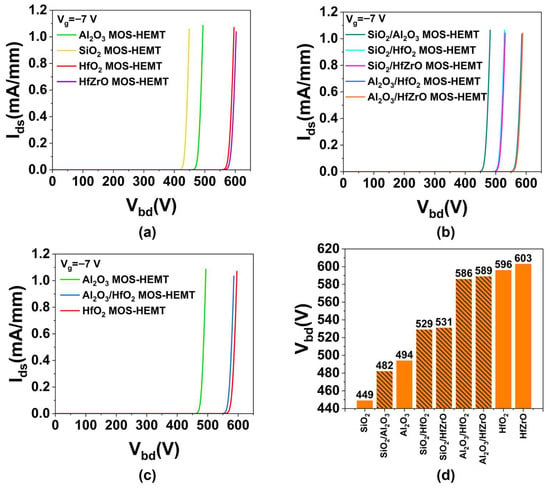
Figure 6.
The Vbd of MOS-HEMTs with (a) uniform gate dielectrics, (b) non-uniform composite gate dielectrics and (c) Al2O3, HfO2, Al2O3/HfO2 gate dielectrics. (d) The Vbd values of all devices.
The device’s gate capacitance and cut-off frequency are shown in Figure 7. Figure 7a presents the Cg-Vg characteristics of Al2O3, HfO2, and Al2O3/HfO2 MOS-HEMTs at Vds = 10 V. As Vg increases, Cg rises slowly initially, increases rapidly in the linear region, and flattens out in the saturation region, reaching a maximum at Vg = 3 V. The Cg values are 396, 474, and 428 pF/mm, respectively, differing mainly due to the dielectric constants of the materials [35]. Figure 7b summarizes the simulated Cg for nine devices, showing a positive correlation with dielectric constant. Figure 7c presents the fT-Vg curves for the three devices. The Al2O3 MOS-HEMT peaks at fT = 36.5 MHz (Vg = −1.4 V), while the HfO2 and Al2O3/HfO2 devices peak at 24.5 MHz (Vg = 2.8 V) and 29.4 MHz (Vg = 2.2 V), respectively. Based on the approximation [36]:
the increase in fT is mainly due to reduced Cg, with a minor contribution from increased gm. As shown in Figure 7d, fT generally decreases with higher dielectric constant [37]. Compared to their uniform higher-k counterparts, the Al2O3/HfZrO, SiO2/Al2O3, SiO2/HfO2, and SiO2/HfZrO MOS-HEMTs show fT improvements of 35.2%, 8.2%, 28.2%, and 44.4%, respectively. These results demonstrate that composite gate dielectrics with LEFT effectively alleviate the fT degradation typical of high-k devices, enabling balanced frequency performance.
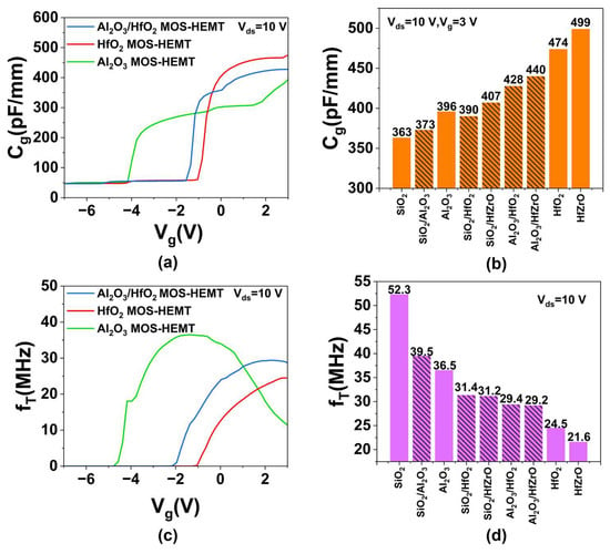
Figure 7.
(a) The Cg-Vg characteristics of Al2O3, HfO2, and Al2O3/HfO2 MOS-HEMT. (b) The Cg values of all devices. (c) The fT-Vg characteristics of Al2O3, HfO2, and Al2O3/HfO2 MOS-HEMT. (d) The maximum fT values of all devices.
4. Discussion
This study simulates and analyzes the electrical characteristics of various gate dielectric structures. The data indicates that the non-uniform composite gate dielectric device with LEFT exhibits Vbd on par with that of uniform higher-k devices, while simultaneously delivering superior gm,max, Ids,max and fT. Specifically, compared to HfO2 and HfZrO MOS-HEMTs, the Al2O3/HfO2 and Al2O3/HfZrO structures show fT improvements of 20.0% and 35.2%, respectively, with only marginal Vbd reductions of 1.7% and 2.3%, as summarized in Figure 8.
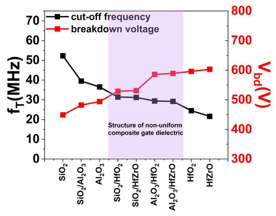
Figure 8.
A summary of breakdown voltage and cut-off frequency of nine different dielectric passivation structures for AlGaN/GaN MOS-HEMT.
5. Conclusions
In summary, we propose a LEFT technique and develop corresponding device structures and TCAD models for both conventional uniform and non-uniform composite gate dielectrics. The simulation models were validated against experimental measurements. The LEFT technique retains a high-k dielectric on the gate-drain side while introducing a lower-k material on the gate-source side. This configuration modulates the electric field distribution, improves channel transport efficiency, and achieves an optimal trade-off between the two critical yet competing metrics: breakdown voltage and cut-off frequency. The core advantage of a non-uniform composite gate dielectric structure lies in its functional zoning. This provides a new approach to resolving the inherent contradictions in HEMTs. The AlGaN/GaN MOS-HEMT with a non-uniform composite gate dielectric structure, shows significant potential for high-voltage and high-frequency applications, such as industrial plasma generators, magnetic resonance imaging systems and biomedical radiofrequency hyperthermia devices.
Author Contributions
Conceptualization, W.H.; methodology, Y.W., J.W., P.T., Z.D., Y.L.; software, Y.W. and Z.D.; validation, W.H., Y.W. and J.W.; formal analysis, Y.W. and J.W.; investigation, Y.W.; resources, W.H., J.Z. and J.W.; data curation, Y.W.; writing—original draft preparation, Y.W.; writing—review and editing, W.H. and J.W.; visualization, Y.W. and J.W.; supervision, W.H. and J.Z.; project administration, W.H. and J.Z.; funding acquisition, W.H. All authors have read and agreed to the published version of the manuscript.
Funding
This research was funded by the Beijing Natural Science Foundation, grant number Z230024; the National Natural Science Foundation of China, grant number 52173298 and 52192611; the National Key R & D Project from the Minister of Science and Technology, grant number 2021YFA1201603.
Data Availability Statement
The raw data supporting the conclusions of this article will be made available by the authors on request.
Conflicts of Interest
The authors declare no conflicts of interest.
References
- van Deurzen, L.; Kim, E.; Pieczulewski, N.; Zhang, Z.; Feduniewicz-Zmuda, A.; Chlipala, M.; Siekacz, M.; Muller, D.; Xing, H.G.; Jena, D.; et al. Using both faces of polar semiconductor wafers for functional devices. Nature 2024, 634, 334–340. [Google Scholar] [CrossRef] [PubMed]
- Chen, C.; Yu, Q.; Liu, S.; Qin, Y. Piezotronic transistors based on GaN wafer for highly sensitive pressure sensing with high linearity and high stability. ACS Nano 2024, 18, 13607–13617. [Google Scholar] [CrossRef] [PubMed]
- Huang, F.; Chen, J.; Ding, Y.; Huang, W. Piezotronic effect on two-dimensional electron gas in AlGaN/GaN heterostructure. Nano Energy 2022, 96, 107098. [Google Scholar] [CrossRef]
- Cong, Z.; Lu, X.; He, Y.; Cai, M.; Wang, X.; Wang, Y.; Ma, X.; Hao, Y. Ferroelectric passivation layer derived high performance AlGaN/GaN heterojunction field-effect transistor. Appl. Phys. Lett. 2023, 123, 212104. [Google Scholar] [CrossRef]
- Hospodková, A.; Hájek, F.; Hubáček, T.; Gedeonová, Z.; Hubík, P.; Hývl, M.; Pangrác, J.; Dominec, F.; Košutová, T. Electron transport properties in high electron mobility transistor structures improved by V-pit formation on the AlGaN/GaN interface. ACS Appl. Mater. Interfaces 2023, 15, 19646–19652. [Google Scholar] [CrossRef]
- Cao, Y.; Pomeroy, J.W.; Uren, M.J.; Yang, F.; Kuball, M. Electric field mapping of wide-bandgap semiconductor devices at a submicrometre resolution. Nat. Electron. 2021, 4, 478–485. [Google Scholar] [CrossRef]
- Nela, L.; Ma, J.; Erine, C.; Xiang, P.; Shen, T.H.; Tileli, V.; Wang, T.; Cheng, K.; Matioli, E. Multi-channel nanowire devices for efficient power conversion. Nat. Electron. 2021, 4, 284–290. [Google Scholar] [CrossRef]
- Shu, J.; Sun, J.; Wu, X.; Chen, K.J. A dynamic two-stage gate driver for unlocking the fast-switching potential of GaN HEMT. IEEE Trans. Power Electron. 2025, 40, 4752–4756. [Google Scholar] [CrossRef]
- Tomita, R.; Ueda, S.; Kawada, T.; Mitsuzono, H.; Horio, K. Analysis of dependence of breakdown voltage on gate-drain distance in AlGaN/GaN HEMTs with high-k passivation layer. IEEE Trans. Electron. Devices 2021, 68, 1550–1556. [Google Scholar] [CrossRef]
- Pharkphoumy, S.; Janardhanam, V.; Jang, T.H.; Park, J.; Shim, K.H.; Choi, C.J. Optimized device geometry of normally-on field-plate AlGaN/GaN high electron mobility transistors for high breakdown performance using TCAD simulation. Electronics 2021, 10, 2642. [Google Scholar] [CrossRef]
- Zeng, D.; Zhang, Z.; Xue, Z.; Zhang, M.; Chu, P.K.; Mei, Y.; Tian, Z.; Di, Z. Single-crystalline metal-oxide dielectrics for top-gate 2D transistors. Nature 2024, 632, 788–794. [Google Scholar] [CrossRef]
- Huang, J.K.; Wan, Y.; Shi, J.; Zhang, J.; Wang, Z.; Wang, W.; Yang, N.; Liu, Y.; Lin, C.H.; Guan, X.; et al. High-κ perovskite membranes as insulators for two-dimensional transistors. Nature 2022, 605, 262–267. [Google Scholar] [CrossRef]
- Schroeder, U.; Park, M.H.; Mikolajick, T.; Hwang, C.S. The fundamentals and applications of ferroelectric HfO2. Nat. Rev. Mater. 2022, 7, 653–669. [Google Scholar] [CrossRef]
- Li, S.; Hu, Q.; Wang, X.; Li, T.; Li, X.; Wu, Y. Improved interface properties and dielectric breakdown in recessed AlGaN/GaN MOS-HEMTs using HfSiOx as gate dielectric. IEEE Electron. Device Lett. 2019, 40, 295–298. [Google Scholar] [CrossRef]
- Li, Q.; Wang, S.; Li, Z.; Hu, X.; Liu, Y.; Yu, J.; Yang, Y.; Wang, T.; Meng, J.; Sun, Q.; et al. High-performance ferroelectric field-effect transistors with ultra-thin indium tin oxide channels for flexible and transparent electronics. Nat. Commun. 2024, 15, 2686. [Google Scholar] [CrossRef] [PubMed]
- Pal, B.; Dhar, B.; See, K.; Katz, H. Solution-deposited sodium beta-alumina gate dielectrics for low-voltage and transparent field-effect transistors. Nat. Mater. 2009, 8, 898–903. [Google Scholar] [CrossRef]
- Cheema, S.S.; Shanker, N.; Wang, L.C.; Hsu, C.H.; Hsu, S.L.; Liao, Y.H.; Jose, M.; Gomez, J.; Chakraborty, W.; Li, W.; et al. Ultrathin ferroic HfO2-ZrO2 superlattice gate stack for advanced transistors. Nature 2022, 604, 65–71. [Google Scholar] [CrossRef]
- Li, W.; Zhou, J.; Cai, S.; Yu, Z.; Zhang, J.; Fang, N.; Li, T.; Wu, Y.; Chen, T.; Xie, X.; et al. Uniform and ultrathin high-κ gate dielectrics for two-dimensional electronic devices. Nat. Electron. 2019, 2, 563–571. [Google Scholar] [CrossRef]
- Turin, V.O. A modified transferred-electron high-field mobility model for GaN devices simulation. Solid-State Electron. 2005, 49, 1678–1682. [Google Scholar] [CrossRef]
- Sze, S.M.; Ng, K.K. Physics of Semiconductor Devices, 3rd ed.; Wiley: Hoboken, NJ, USA, 2006; ISBN 978-0-4711-4323-9. [Google Scholar]
- Ranjan, K.; Arulkumaran, S.; Ng, G.I.; Sandupatla, A. Investigation of self-heating effect on DC and RF performances in AlGaN/GaN HEMTs on CVD-diamond. IEEE J. Electron. Devices Soc. 2019, 7, 1264–1269. [Google Scholar] [CrossRef]
- Heidelberger, G.; Bernát, J.; Fox, A.; Marso, M.; Lüth, H.; Gregušová, D.; Kordoš, P. Comparative study on unpassivated and passivated AlGaN/GaN HFETs and MOSHFETs. Phys. Stat. Sol. (A) 2006, 203, 1876–1881. [Google Scholar] [CrossRef]
- Cai, Y.; Wang, Y.; Liang, Y.; Zhang, Y.; Liu, W.; Wen, H.; Mitrovic, I.Z.; Zhao, C. Effect of high-k passivation layer on high voltage properties of GaN metal-insulator-semiconductor devices. IEEE Access 2020, 8, 95642–95649. [Google Scholar] [CrossRef]
- Wang, W.; Derluyn, J.; Germain, M.; Leys, M.; Degroote, S.; Schreurs, D.; Borghs, G. Effect of surface passivation on two-dimensional electron gas carrier density in AlGaN/GaN structures. Jpn. J. Appl. Phys. 2006, 45, 224–226. [Google Scholar] [CrossRef]
- Chowdhury, A.R.; Mauch, D.; Joshi, R.P.; Neuber, A.A.; Dickens, J. Contact extensions over a high-k dielectric layer for surface field mitigation in high power 4H-SiC photoconductive switches. IEEE Trans. Electron. Devices 2016, 63, 3171–3176. [Google Scholar] [CrossRef]
- Belkhiria, M.; Echouchene, F.; Jaba, N.; Bajahzar, A.; Belmabrouk, H. Impact of high-k gate dielectric on self-heating effects in PiFETs structure. IEEE Trans. Electron. Devices 2020, 67, 3522–3529. [Google Scholar] [CrossRef]
- Kaushal, V.; Íñiguez-de-la-Torre, I.; González, T.; Mateos, J.; Lee, B.; Misra, V.; Margala, M. Effects of a High-k Dielectric on the Performance of III–V Ballistic Deflection Transistors. IEEE Electron. Device Lett. 2012, 33, 1120–1122. [Google Scholar] [CrossRef]
- Hao, L.; Xu, K.; Guo, H.; Shao, P.; Ye, J.; Zhou, Y.; Liu, B.; Lu, H.; Zhang, R.; Zheng, Y.; et al. Enhanced performance of normally-off AlGaN/GaN MOS-HEMTs taking advantage of extreme-k BaTiO3 with prominent dielectric polarization. Appl. Phys. Lett. 2025, 127, 062103. [Google Scholar] [CrossRef]
- Hahn, H.; Benkhelifa, F.; Ambacher, O.; Brunner, F.; Noculak, A.; Kalisch, H.; Vescan, A. Threshold voltage engineering in GaN-based HFETs: A systematic study with the threshold voltage reaching more than 2 V. IEEE Trans. Electron. Devices 2015, 62, 538–545. [Google Scholar] [CrossRef]
- Palmer, H.B. The capacitance of a parallel-plate capacitor by the Schwartz-Christoffel transformation. Trans. Am. Inst. Electr. Eng. 1937, 56, 363–366. [Google Scholar] [CrossRef]
- Asllani, B.; Fayyaz, A.; Castellazzi, A.; Morel, H.; Planson, D. VTH subthreshold hysteresis technology and temperature dependence in commercial 4H-SiC MOSFETs. Microelectron. Reliab. 2018, 88–90, 604–609. [Google Scholar] [CrossRef]
- Murugapandiyan, P.; Revathy, A.; Ramkumar, N.; Kumar, R.S.; Mohanbabu, A. Comparative study of AlGaN/InGaN/β-Ga2O3 and InAlN/InGaN/β-Ga2O3 HEMTs for enhanced RF linearity. J. Electron. Mater. 2025, 54, 2340–2354. [Google Scholar] [CrossRef]
- Hanawa, H.; Satoh, Y.; Horio, K. Effects of buffer leakage current on breakdown characteristics in AlGaN/GaN HEMTs with a high-k passivation layer. Microelectron. Eng. 2015, 147, 96–99. [Google Scholar] [CrossRef]
- Western, N.J.; Perez-Wurfl, I.; Wenham, S.R.; Bremner, S.P. Point-contacting by localized dielectric breakdown with breakdown fields described by the Weibull distribution. IEEE Trans. Electron. Devices 2015, 62, 1826–1830. [Google Scholar] [CrossRef]
- Bothe, K.M.; von Hauff, P.A.; Afshar, A.; Foroughi-Abari, A.; Cadien, K.C.; Barlage, D.W. Electrical comparison of HfO2 and ZrO2 gate dielectrics on GaN. IEEE Trans. Electron. Devices 2013, 60, 4119–4124. [Google Scholar] [CrossRef]
- Singh, S.; Thakar, K.; Kaushik, N.; Muralidharan, B.; Lodha, S. Performance projections for two-dimensional materials in radio-frequency applications. Phys. Rev. Appl. 2018, 10, 014022. [Google Scholar] [CrossRef]
- Padhi, P.S.; Rai, S.K.; Srivastava, H.; Ajimsha, R.S.; Srivastava, A.K.; Misra, P. Maxwell-Wagner relaxation-driven high dielectric constant in Al2O3/TiO2 nanolaminates grown by pulsed laser deposition. ACS Appl. Mater. Interfaces 2022, 14, 12873–12882. [Google Scholar] [CrossRef]
Disclaimer/Publisher’s Note: The statements, opinions and data contained in all publications are solely those of the individual author(s) and contributor(s) and not of MDPI and/or the editor(s). MDPI and/or the editor(s) disclaim responsibility for any injury to people or property resulting from any ideas, methods, instructions or products referred to in the content. |
© 2025 by the authors. Licensee MDPI, Basel, Switzerland. This article is an open access article distributed under the terms and conditions of the Creative Commons Attribution (CC BY) license (https://creativecommons.org/licenses/by/4.0/).