1. Introduction
Micro-Electro-Mechanical Systems (MEMS) gyroscopes have emerged as a cornerstone technology for inertial sensing across a broad spectrum of applications, from consumer electronics to high-precision navigation and autonomous platforms, where stringent requirements on bias stability, scale-factor linearity, and long-term robustness must be satisfied [
1,
2,
3]. With performance specifications becoming increasingly stringent, parasitic coupling between drive and sense electrodes—commonly referred to as feedthrough—has become a major factor limiting attainable sensing accuracy and closed-loop control fidelity. Such feedthrough predominantly originates from fabrication- and layout-induced parasitics that give rise to capacitive coupling, which in turn introduces spurious components at the drive frequency into the sensing path, thereby distorting the frequency response and undermining scale-factor stability [
4,
5,
6,
7].
Several approaches have been investigated to mitigate feedthrough interference in MEMS gyroscopes. Structural and electrode optimization seeks to suppress mutual capacitance or geometrically cancel parasitic coupling through symmetric layouts, shielding structures, or modified electrode topologies. Representative implementations include differential comb geometries, grounded shielding layers, and electrode relocation to minimize direct capacitive paths [
8,
9]. While such methods can alleviate feedthrough during the design stage, they generally require substantial redesign effort and cannot fully eliminate residual coupling introduced by fabrication tolerances or environmental variations after deployment [
10,
11,
12].
2. MEMS Gyroscope Modeling
2.1. Basic Architecture of MEMS Gyroscopes
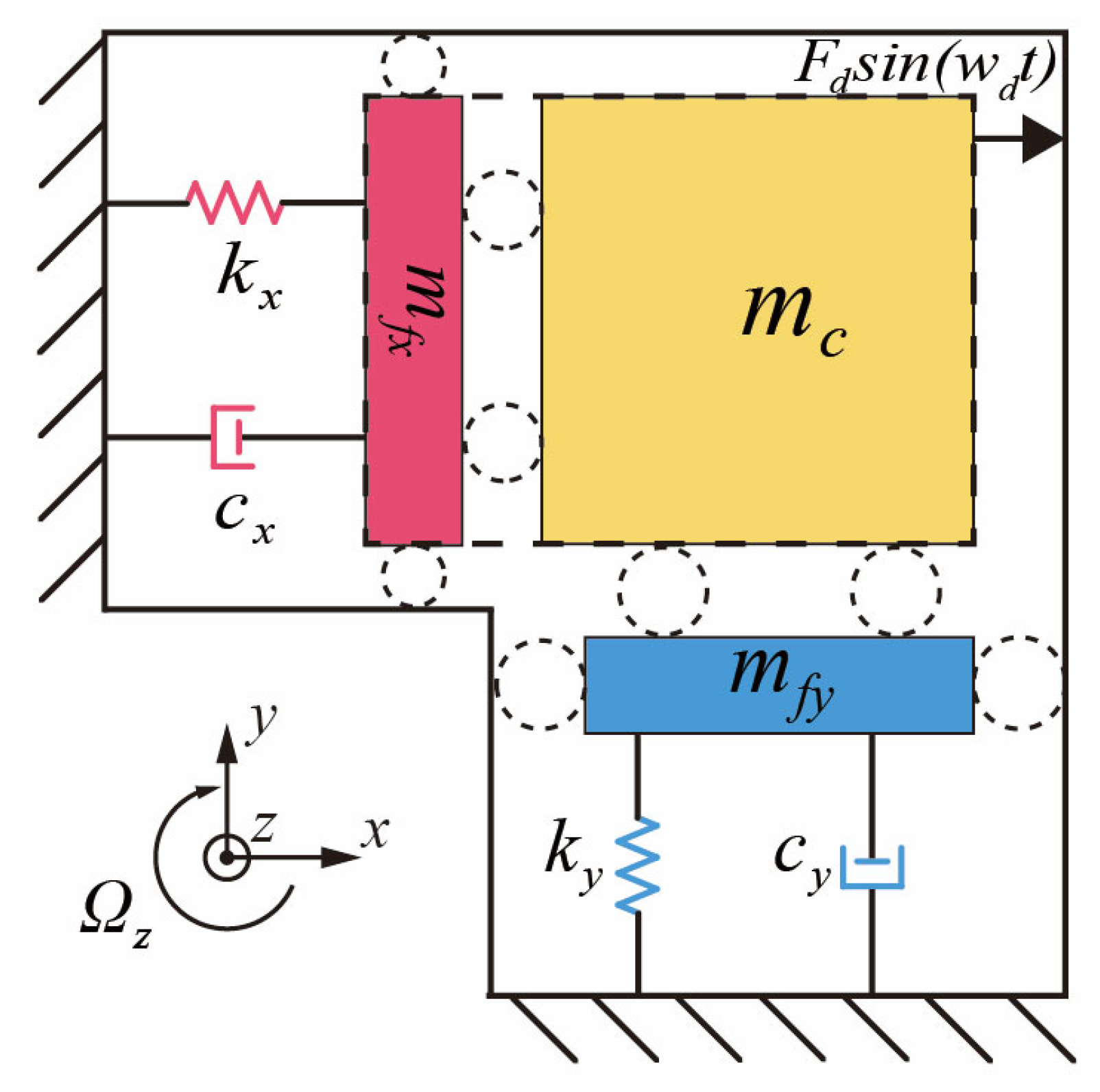
As depicted in
Figure 1, a basic MEMS vibratory gyroscope operates with uncoupled drive and sense modes, which can be modeled as a two-dimensional oscillator [
13]. According to Newton’s second law, simplified dynamics equations for the drive mode and sense mode of the MEMS gyroscope are obtained as follows [
14]:
where
and
denote the damping coefficients, and
and
the stiffness coefficients along the
x- and
y-axes, respectively. Here,
represents the equivalent mass of the Coriolis mass block, while the equivalent masses of the drive and sense modes are expressed as
and
, respectively.
corresponds to the driving force applied along the drive axis,
represents the Coriolis force generated by the angular velocity about the
z-axis during drive-mode operation, and
is the feedback force in force-balance mode, used to counteract the sense-mode vibration along the
y-axis.
An equivalent representation of Equation (1) is given by
where
and
denote the resonance frequencies of the drive and sense modes,
and
are the corresponding quality factors, and
represents the amplitude of the drive-mode vibration.
2.2. Capacitive Feedthrough Model
In MEMS gyroscopes, electrostatic excitation is a widely adopted actuation method, often realized through a differential push-pull configuration. This approach involves applying two sinusoidal signals, possessing identical amplitude and opposing phase, to the drive electrodes. The resulting feedback force
can be expressed as
where
denotes the capacitance of the drive combs in the sense mode,
refers to the DC voltage applied to the proof mass, and
signifies the amplitude of the AC excitation signal applied to the fixed electrodes.
Under electrostatic actuation and capacitive sensing, the drive signal can couple into the sensing path via parasitic capacitance between the drive and sense electrodes, thereby introducing interference into the readout. The parasitic capacitance topology has been thoroughly investigated in previous studies [
15,
16,
17]. As the dominant feedthrough originates from capacitive coupling between the drive and sense electrodes in the sense mode, the feedthrough capacitance model is accordingly simplified, as illustrated in
Figure 2.
Figure 2 illustrates the labeling convention used for feedthrough capacitances: the first subscript indicates the polarity of the drive electrode, and the second denotes that of the sense electrode (“1” represents the positive AC signal applied to the electrode, and “2” represents the negative AC signal). The differential excitation signals are defined as
, where
denotes the amplitude of the excitation signal, and
its angular frequency. These signals are applied to the gyroscope’s drive combs in an anti-phase configuration to realize push–pull actuation. The feedback resistor of the charge-sensitive amplifier (CSA) is denoted by
, and the resulting feedthrough voltage after differential amplification is represented by
. The transfer function of the charge-sensitive amplifier (CSA) is given by
The CSA feedback resistor and gain capacitor are designed to satisfy
, where ω denotes the frequency of variation in the sensing capacitance [
18]. Based on the equivalent circuit model [
19], the corresponding relationship between the feedthrough and drive signals is derived as
Equation (5) indicates that, under conventional excitation schemes, the feedthrough signal possesses the same frequency and phase as the excitation signal. This spectral coincidence prevents effective separation from the gyroscopic vibration response in the frequency domain, thereby posing a fundamental challenge to feedthrough suppression.
3. Feedthrough Suppression Scheme Based on Mixed-Frequency Excitation
3.1. Theoretical Analysis
This section presents a feedthrough suppression scheme based on mixed-frequency excitation, along with its underlying modulation principle. In this approach, a modulated signal is applied to drive the harmonic oscillation of the gyroscope, which concurrently shifts the feedthrough component to a higher frequency band. As a result, the desired signal and feedthrough interference become spectrally separable, facilitating subsequent suppression. The excitation signal is defined as follows:
where
is a chopper signal applied to modulate the excitation path. It has a 50% duty cycle, an amplitude of ±1, and a period of Tₛ [
20]. The bias injection signal b(t) shares the same periodicity. The definitions of q(t) and b(t) are given as follows:
Given that q
2(t) = 1, the corresponding electrostatic force on the drive combs is expressed as
For δ = 2, the electrostatic force produced by the mixed-frequency excitation signal is indistinguishable from that generated by the conventional excitation method. Under mixed-frequency excitation, both the closed-loop control input signals and the electrostatic forces from the drive electrodes remain the same as those in the conventional excitation scheme. As a result, the effective displacement response of the resonator remains unaltered, thereby confirming that the mixed-frequency excitation method theoretically maintains the linear characteristics inherent to the conventional excitation approach without necessitating additional demodulation circuitry [
21].
According to the feedthrough capacitance model depicted in
Figure 2, the feedthrough current
generated at the sense electrode under the mixed-frequency excitation scheme is given by
Expanding the square wave signals from Equation (10) into their Fourier series yields
where n = 1, 2, 3, …, ∞, and
= 2π/
denotes the angular frequency of the square wave. Equation (11) demonstrates that when a mixed-frequency excitation signal is employed, the resultant feedthrough current is modulated to the frequency bands of
and n
. If
is set to be significantly higher than the gyroscope’s operational frequency, the feedthrough signal and the desired signal can be effectively separated through filtering.
Equation (6) is expressed as follows:
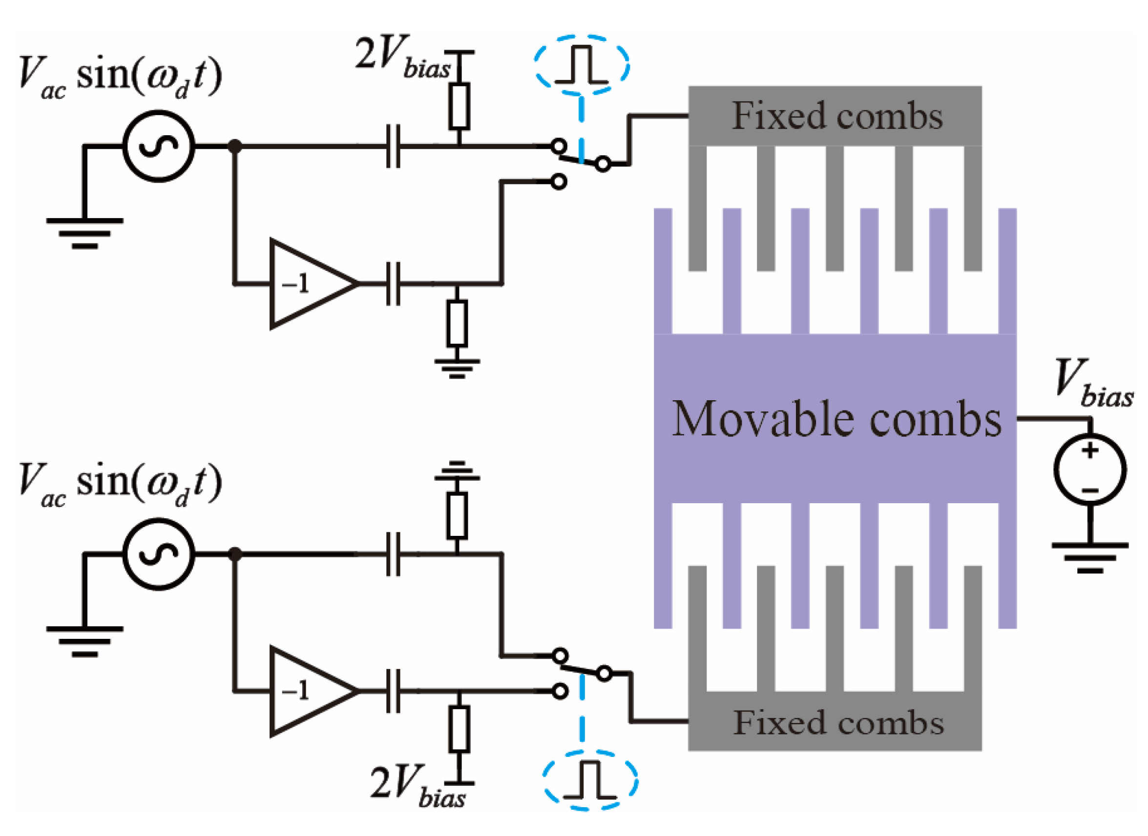
In conformity with Equations (12) and (13), the mixed-frequency excitation signal generation circuit is configured as depicted in
Figure 3. This circuit accepts a sinusoidal input signal at the gyroscope’s operational frequency [
22]. The input signal is subsequently divided into two differential paths, thereby enabling a mixing operation facilitated by single-pole double-throw (SPDT) analog switches. Both switches maintain an identical initial position and are governed by a common square wave signal. Prior to the chopping operation at the switch nodes, one of the sinusoidal paths is subjected to a DC bias, precisely twice the magnitude of the center plate voltage, applied via a pull-up resistor. Concurrently, a coupling capacitor is employed to preclude the leakage of this DC bias into the preceding circuitry.
3.2. Mixed-Frequency Excitation Structure and Control System
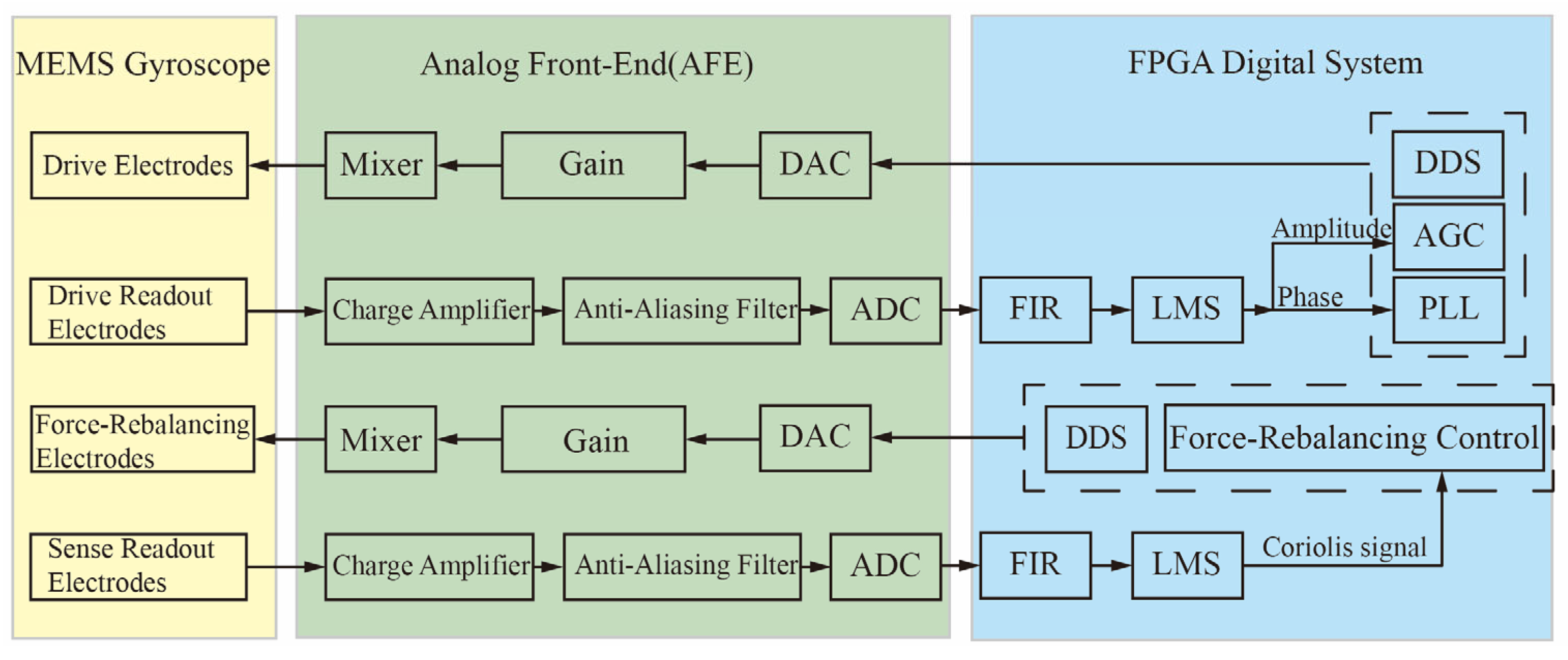
Figure 4 illustrates the Mixed-Frequency Excitation Structure and Control System constructed based on the mixed-frequency excitation signal generation circuit. A Phase-Locked Loop (PLL) and an Automatic Gain Control (AGC) scheme are employed to achieve closed-loop control of the gyroscope’s drive mode. Simultaneously, a force-rebalancing scheme is adopted to implement closed-loop sensing. A mixed-frequency module is integrated into the drive/force-rebalancing excitation signal generation circuit. In the readout path, an anti-aliasing low-pass filter is employed to preliminarily filter the mixed-frequency feedthrough signal, thereby ensuring its separation from the desired signal and precluding aliasing during ADC sampling. Upon its entry into the digital processing domain, the digitized signal is subjected to a Finite Impulse Response (FIR) bandpass filter for the further suppression of the feedthrough. Ultimately, a Least Mean Squares (LMS) demodulation algorithm is utilized to extract the control parameters for the drive and sense loops, with a Proportional-Integral (PI) controller executing the closed-loop control.
4. Analysis of Non-Idealities
The mixed-frequency signal generation circuit utilizes an op-amp based inverter to convert the sinusoidal signal into a differential signal. Stemming from non-idealities such as the operational amplifier’s gain-bandwidth product and the precision of the feedback resistor, the differential signal exhibits an amplitude mismatch of (1 − α) and a phase mismatch of β. This consequently degrades the quality of the mixed-frequency signal. The resulting non-ideal mixed-frequency excitation signal is thus defined as
First, we analyze the impact of these mismatches on the excitation performance. Based on the principle of electrostatic actuation, the electrostatic force generated by the excitation signal is given by
Its Fourier series expansion is given by
With a frequency counter, it was revealed that the differential signal’s phase mismatch (β) was approximately 2°, while the amplitude mismatch (1 − α) was about 1%. Under non-ideal conditions, the mixed-frequency excitation signal generates an electrostatic force that contains high-frequency components according to Equation (17). After normalization, the maximum amplitude was calculated to be −53.68 dB. Given that the gyroscope utilized in this study possesses a high quality factor of 200,000, its sensitivity to high-frequency components is minimal. As a result, the influence of these components can be reasonably neglected in subsequent analysis.
To further investigate the impact of non-ideal factors on the suppression of feedthrough interference, the non-ideal mixing excitation signal
is analyzed via Fourier decomposition.
Equation (18) shows that mismatch parameters introduce fundamental frequency residual. Based on the given parameter values, the cosine and sine components of the residual signal are calculated to be 0.017 and −0.005, respectively. After being coupled to the gyroscope readout end through the feedthrough capacitor, this residual cannot be effectively separated by the filtering circuit, thereby undermining the suppression of feedthrough interference.
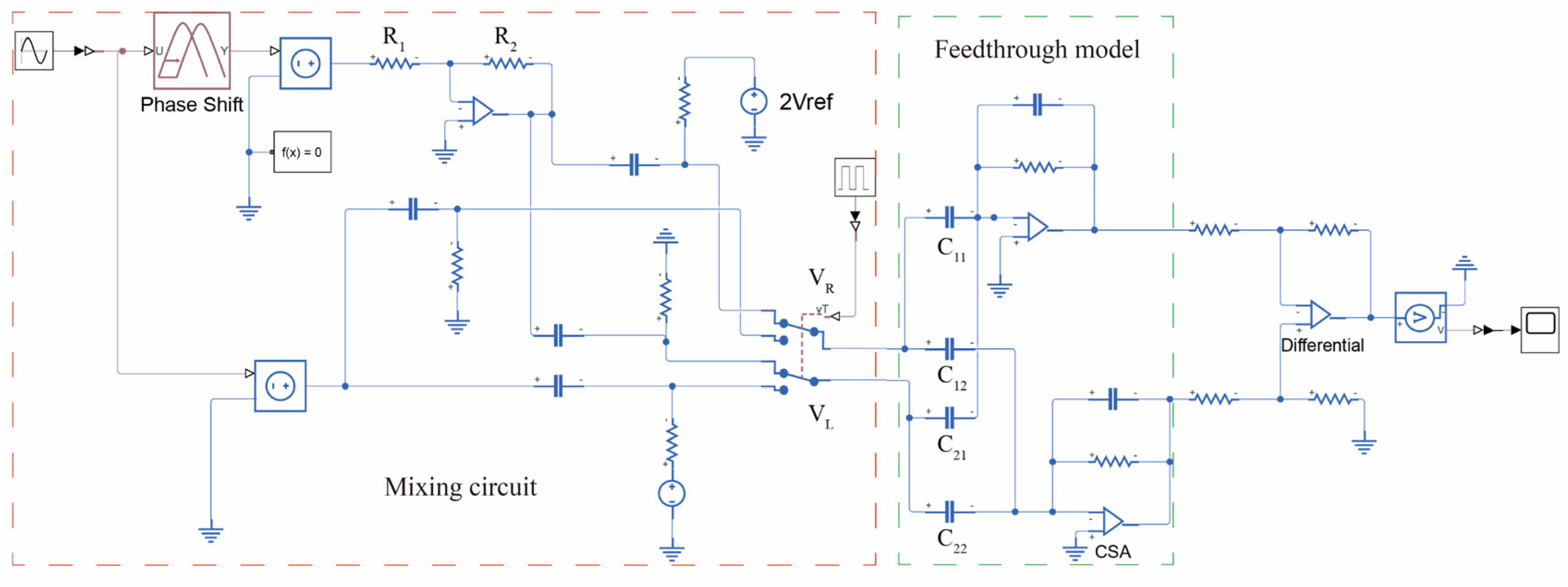
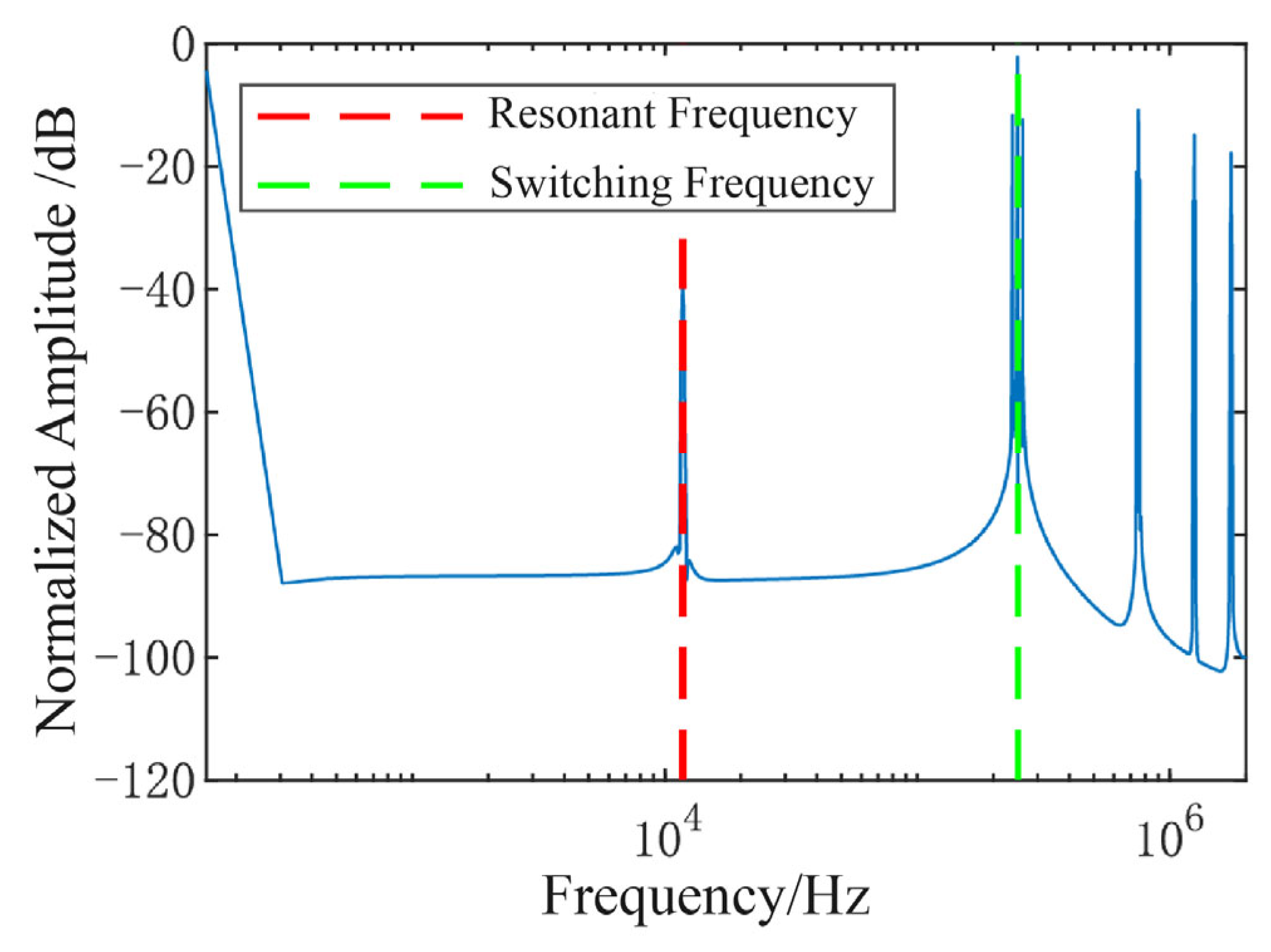
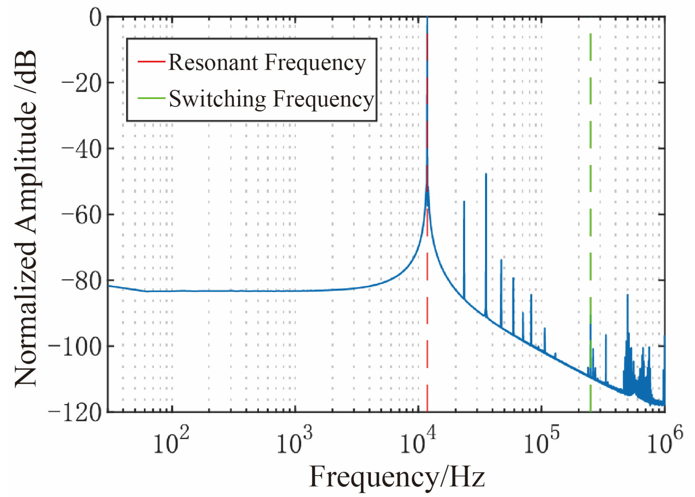
Figure 5 illustrates the simulation model of the mixed-frequency signal generation circuit under non-ideal conditions. Phase mismatch is implemented using a dedicated phase-shifting module, whereas amplitude mismatch is introduced by adjusting the resistance of R1 and R2. A sinusoidal signal with an amplitude of 1.5 V and a frequency matching the resonant frequency is then applied as the input. A Discrete Fourier Transform (DFT) analysis is performed on the mixed signal, with the resulting spectrum plot shown in
Figure 6.
Simulation results reveal that, in the presence of non-idealities, the mixed-frequency excitation signal suffers from two dominant interferences: high-frequency artifacts introduced by modulation and fundamental residual at the resonant frequency.
Under non-ideal conditions, the mismatch parameters of the excitation signals
and
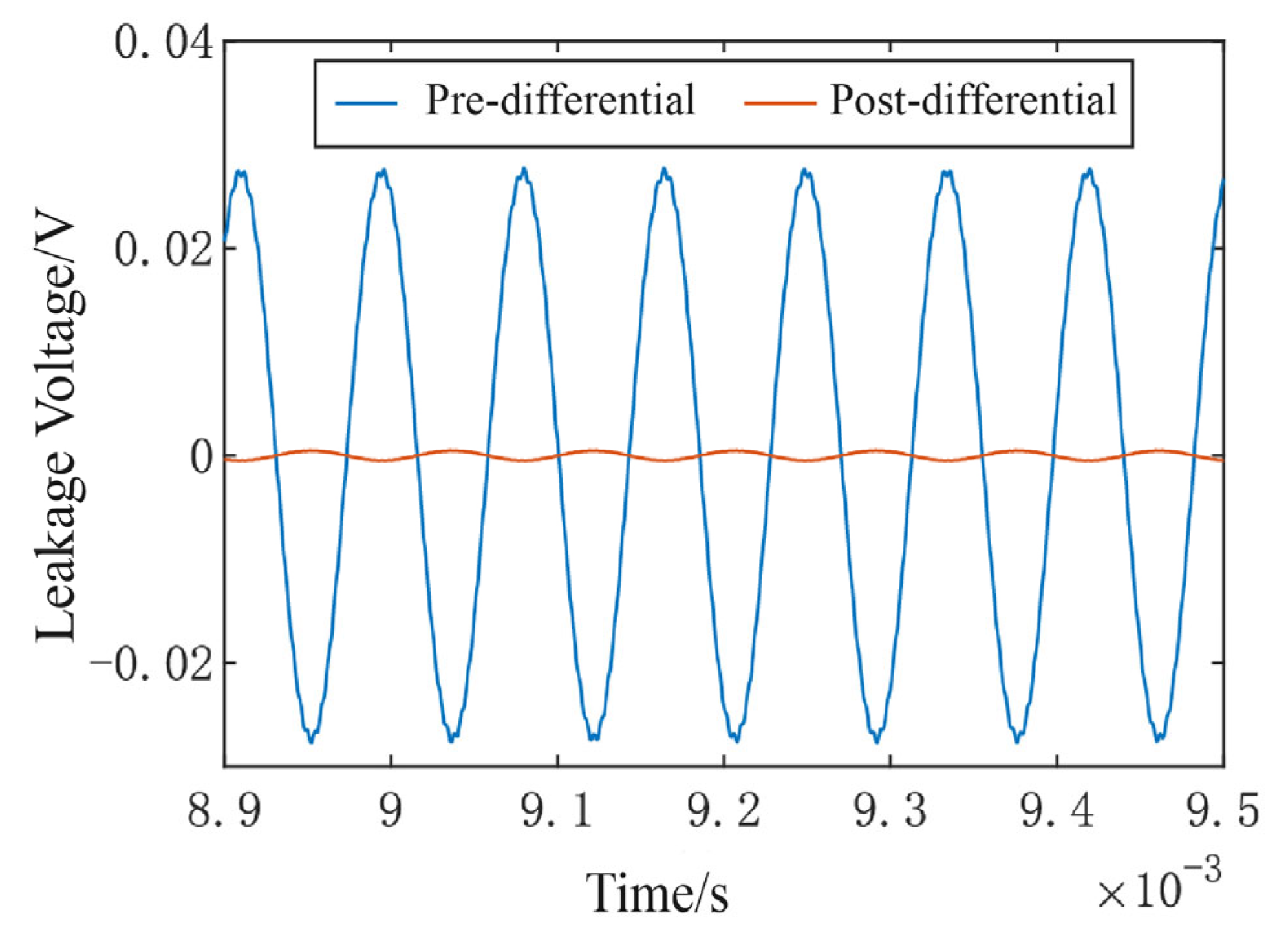
are assumed to be identical, leading to fundamental frequency residual that exhibits a common-mode characteristic. Consequently, such a residual can be effectively suppressed using differential circuit techniques. To verify this behavior, a non-ideal mixed-frequency excitation signal is applied to the feedthrough capacitance model. After passing through a low-pass filter to eliminate high-frequency components, the residual fundamental frequency is extracted and analyzed. The corresponding simulation results are illustrated in
Figure 7.
The results demonstrate that the differential circuit effectively suppresses fundamental frequency residuals caused by mismatches, reducing the amplitude of the feedthrough signal coupled into the readout path at the resonant frequency from 50 mV to less than 1 mV.
5. Experiments
To validate the feasibility of the mixed-frequency excitation approach, the measurement and control system outlined in
Section 3 was employed to realize closed-loop control of both the drive and sense modes of the gyroscope.
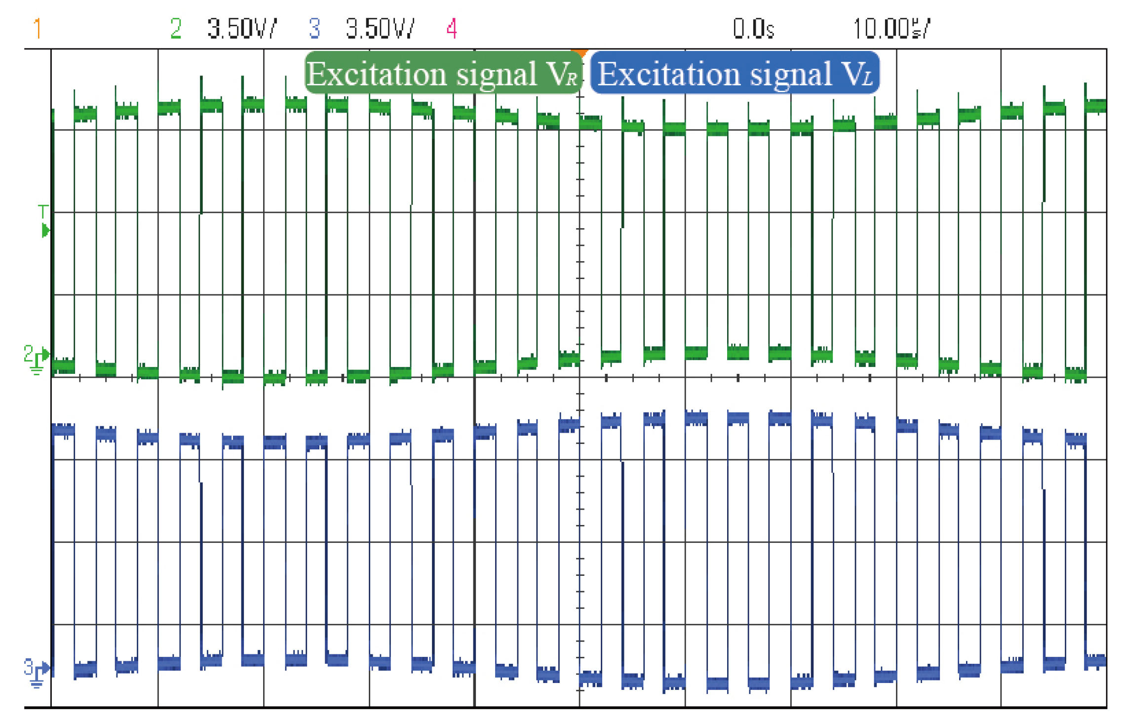
Figure 8 presents a photograph of the physical control circuit.
Figure 9 presents the oscilloscope-captured waveform of the mixed-frequency excitation signal. The mixed-frequency excitation signal exhibits an envelope modulation pattern, where the outer envelope shares the same frequency and amplitude as the input sinusoidal signal. The two mixed components are 180° out of phase in their envelope waveforms. Additionally, the square-wave carriers possess identical frequencies and maintain a 180° phase difference, in agreement with theoretical predictions.
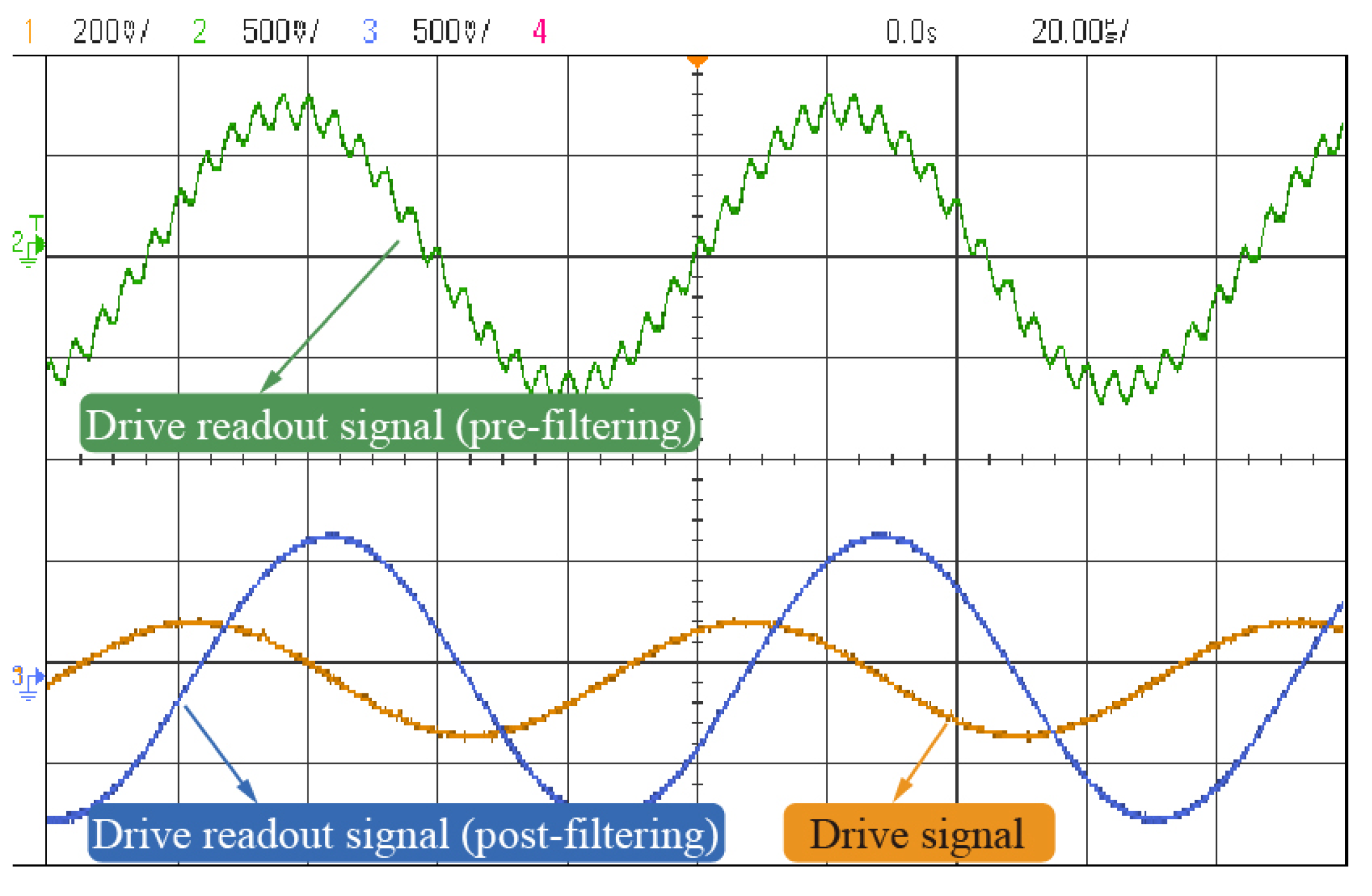
Figure 10 shows the waveform of the stabilized drive-mode signal before and after filtering. The comparison indicates that high-frequency feedthrough components are effectively suppressed. Additionally, the filtered readout signal exhibits a 90° phase shift with respect to the original drive signal, confirming that the gyroscope is operating at resonance.
The filtered drive-mode readout signal was sampled and analyzed via Discrete Fourier Transform (DFT), and the resulting frequency spectrum is presented in
Figure 11. The results indicate that high-frequency components are negligible, confirming the elimination of feedthrough interference and retention of the drive-mode signal.
Feedthrough interference adversely affects the resonant characteristics of MEMS gyroscopes, typically manifesting as an anti-resonant notch in the frequency response curve [
23,
24]. To validate the effectiveness of the proposed mixed-frequency excitation approach in suppressing feedthrough interference, open-loop frequency response measurements were carried out under both the conventional and mixed-frequency excitation conditions. During these experiments, the excitation amplitude was kept constant while the input frequency was linearly swept across a ±400 Hz range centered around the sense-mode resonant frequency. The corresponding frequency response curves are presented in
Figure 12.
The results reveal that, under conventional excitation, the gyroscope exhibits a resonant peak accompanied by an anti-resonant zero near 12,023 Hz, indicative of significant feedthrough effects. In contrast, when subjected to the proposed mixed-frequency excitation, the anti-resonant feature disappears, and the frequency response presents a well-defined resonant peak. This observation confirms, from a frequency-domain perspective, the efficacy of the proposed approach in suppressing feedthrough interference.
In the gyroscope’s force-balanced mode, feedthrough interference compromises the scale factor [
25,
26] by causing the closed-loop scale factor to vary with the mode frequency split; the more pronounced the interference, the greater the resulting deviation.
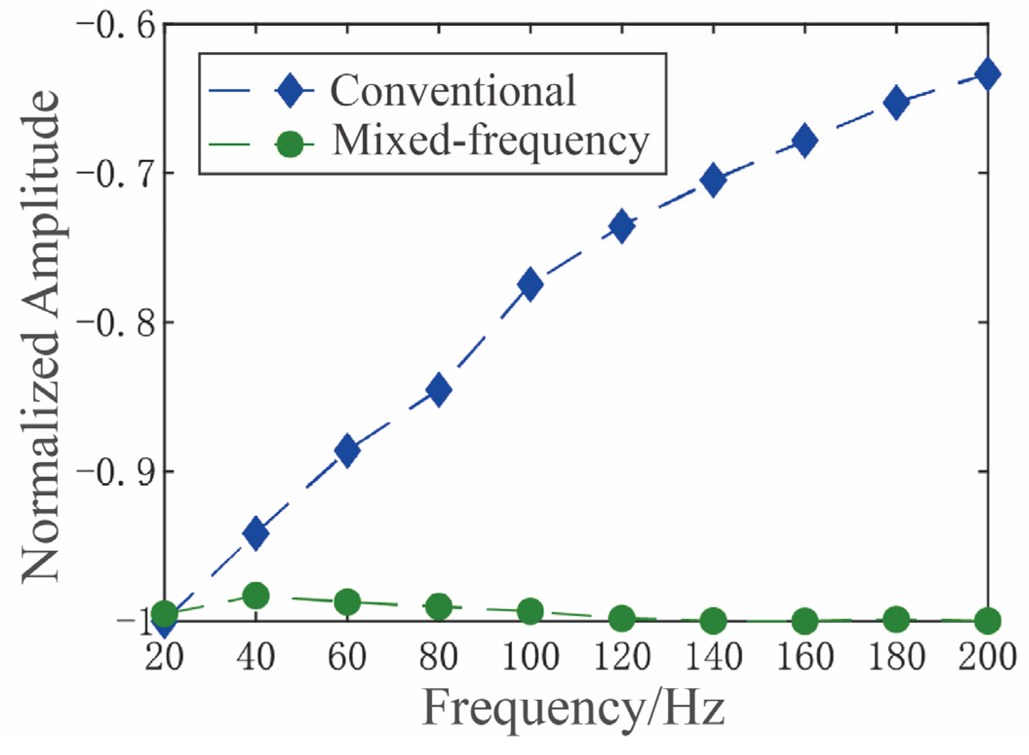
For the same MEMS gyroscope, both a conventional and a mixed-frequency excitation scheme were employed to implement force-balanced detection. The scale factor was then measured using a high-precision rate-position turntable under both control schemes, with the mode frequency split swept from 20 Hz to 200 Hz in 20 Hz increments. The resulting test data and the corresponding normalized scale factor variation curve are presented in
Table 1 and
Figure 13, respectively.
Under conventional excitation, the gyroscope’s scale factor decreased by 36.65% as the mode frequency split increased from 20 Hz to 200 Hz. In contrast, with the proposed mixed-frequency excitation, the maximum scale factor variation was limited to 1.7% over the same frequency split range—a 21-fold reduction in fluctuation. This demonstrates the effectiveness of the proposed approach in suppressing feedthrough interference from the perspective of scale factor stability.
The Zero-bias performance tests were conducted on MEMS gyroscopes under both a conventional and a mixed-frequency excitation approach. The tests yielded mean bias stability values of 0.2782
and 0.2731
for each approach, respectively, along with mean angular random walk values of 0.2757
and 0.2405
, respectively. The negligible difference in static performance between the two approaches indicates that the mixed-frequency excitation does not degrade the gyroscope’s static performance. The full test results are shown in
Table 2.
6. Conclusions
This study presents a comprehensive theoretical investigation of feedthrough interference in MEMS vibratory gyroscopes. An equivalent relationship between the feedthrough signal and the excitation signal is derived, forming the theoretical foundation for a novel suppression strategy based on mixed-frequency excitation. By exploiting the quadratic dependence of electrostatic force on the excitation signal, the proposed method employs a switching circuit to modulate the excitation, effectively shifting the feedthrough interference to higher frequencies. This modulation enables frequency-domain separation between the interference and the desired vibratory signal.
The efficacy of the proposed approach was validated through a series of experimental evaluations. Open-loop frequency response measurements confirmed that mixed-frequency excitation effectively eliminates the anti-resonant artifacts introduced by feedthrough interference. Additionally, scale factor characterization revealed that the proposed method reduces the maximum fluctuation in the closed-loop scale factor by a factor of 21 compared to conventional excitation, confirming significant feedthrough suppression from both frequency and scale-factor perspectives. Finally, static performance testing demonstrated a mean bias stability of 0.3118 and a mean angular random walk of 0.2443 , underscoring the approach’s potential for high-performance MEMS gyroscope applications.
In perspective, the proposed strategy effectively mitigates the scale factor instability of MEMS gyroscopes under frequency tuning conditions, thereby improving measurement accuracy. This enhanced stability not only strengthens the reliability of MEMS gyroscopes in laboratory evaluations, but also provides significant benefits for practical applications such as high-precision navigation, inertial measurement systems, and autonomous platforms, where long-term accuracy and robustness against environmental variations are critical.
Author Contributions
Conceptualization, H.L. (Hongsheng Li) and H.L. (Hongjie Lei); methodology, X.C. and Z.P.; validation, C.Z. and J.H.; formal analysis, X.C. and Z.P.; experiments, C.Z. and J.H.; resources Y.W.; writing—original draft preparation, X.C. and Z.P.; writing—review and editing C.Z.; supervision, J.H. All authors have read and agreed to the published version of the manuscript.
Funding
This research received no external funding.
Data Availability Statement
The original contributions presented in this study are included in the article. Further inquiries can be directed to the corresponding author.
Conflicts of Interest
The authors declare no conflict of interest. Hongjie Lei is a employee of Aviation Industry Corporation of China. The paper reflects the views of the scientists, and not the company.
References
- Shaeffer, D.K. MEMS inertial sensors: A tutorial overview. IEEE Commun. Mag. 2013, 51, 100–109. [Google Scholar] [CrossRef]
- Zhanshe, G.; Fucheng, C.; Boyu, L.; Le, C.; Chao, L.; Ke, S. Research development of silicon MEMS gyroscopes: A review. Microsyst. Technol. 2015, 21, 2053–2066. [Google Scholar] [CrossRef]
- Greiff, P.; Boxenhorn, B.; King, T.; Niles, L. Silicon monolithic micromechanical gyroscope. In Proceedings of the TRANSDUCERS’91: 1991 International Conference on Solid-State Sensors and Actuators, Digest of Technical Papers, San Francisco, CA, USA, 24–27 June 1991; pp. 966–968. [Google Scholar]
- Ding, X.; Xu, Q.; Ge, X.; Liu, X.; Zhao, L.; Li, H. Analysis and Compensation of Electrical Feedthrough Effect on Scale Factor of Force-to-Rebalanced MEMS Gyroscopes. IEEE Sensors J. 2024, 25, 301–312. [Google Scholar] [CrossRef]
- Askari, S.; Asadian, M.H.; Shkel, A.M. Performance of quad mass gyroscope in the angular rate mode. Micromachines 2021, 12, 266. [Google Scholar] [CrossRef] [PubMed]
- Endean, D.; Christ, K.; Duffy, P.; Freeman, E.; Glenn, M.; Gnerlich, M.; Johnson, B.; Weinmann, J. Near-Navigation Grade Tuning Fork MEMS Gyroscope. In Proceedings of the 2019 IEEE International Symposium on Inertial Sensors and Systems (INERTIAL), Naples, FL, USA, 1–5 April 2019; pp. 1–4. [Google Scholar]
- Yang, Y.; Chen, L.; Liu, C.; Zhang, X. Two-Parameter Frequency Tracker and Its Application of Semi-active Suspension with Inerter. J. Vib. Eng. Technol. 2023, 12, 3905–3917. [Google Scholar] [CrossRef]
- Alper, S.E.; Akin, T. A single-crystal silicon symmetrical and decoupled gyroscope on insulating substrate. In Proceedings of the TRANSDUCERS’03 12th International Conference on Solid-State Sensors, Actuators and Microsystems Digest of Technical Papers (Cat No 03TH8664), Boston, MA, USA, 8–12 June 2003; IEEE: New York, NY, USA, 2003. [Google Scholar]
- Xu, Y.; Lee, J.E.-Y. Single-device and on-chip feedthrough cancellation for hybrid MEMS resonators. IEEE Trans. Ind. Electron. 2011, 59, 4930–4937. [Google Scholar] [CrossRef]
- Di, Y.; Tang, H.; Zhou, Y.; Yu, Z.; Zhou, T.; Su, Y. Research on Closed-Loop Control Method of MEMS Disk Resonant Gyroscope Based on Dual-Modal Parametric Excitation. In Proceedings of the 2024 IEEE 7th Information Technology, Networking, Electronic and Automation Control Conference (ITNEC), Chongqing, China, 20–22 September 2024; pp. 1767–1771. [Google Scholar]
- Wang, Y.; Fu, Q.; Zhang, Y.; Zhang, W.; Chen, D.; Yin, L.; Liu, X. A Digital Closed-Loop Sense MEMS Disk Resonator Gyroscope Circuit Design Based on Integrated Analog Front-end. Sensors 2020, 20, 687. [Google Scholar] [CrossRef] [PubMed]
- Cao, H.; Li, H.; Liu, J.; Shi, Y.; Tang, J.; Shen, C. An improved interface and noise analysis of a turning fork micro gyroscope structure. Mech. Syst. Signal Process. 2016, 70, 1209–1220. [Google Scholar] [CrossRef]
- Kangul, M.; Aydin, E.; Gokce, F.; Zorlu, O.; Kulah, H. Analysis and elimination of the capacitive feedthrough current on electrostatically actuated and sensed resonance-based MEMS sensors. J. Microelectromech. Syst. 2017, 26, 1272–1278. [Google Scholar] [CrossRef]
- Cao, H.; Li, H.; Shao, X.; Liu, Z.; Kou, Z.; Shan, Y.; Shi, Y.; Shen, C.; Liu, J. Sensing mode coupling analysis for dual-mass MEMS gyroscope and bandwidth expansion within wide-temperature range. Mech. Syst. Signal Process. 2018, 98, 448–464. [Google Scholar] [CrossRef]
- Yang, Y.; Liu, C.; Chen, L.; Zhang, X.; Zuo, L. Semi-Active Suspension with Power Driven Inerter and Its Performance Evaluation. J. Vib. Eng. Technol. 2024, 12 (Suppl. S1), 307–319. [Google Scholar] [CrossRef]
- Yang, Y.; Liu, C.; Chen, L.; Zhang, X. Phase deviation of semi-active suspension control and its compensation with inertial suspension. Acta Mech. Sin. 2024, 40, 523367. [Google Scholar] [CrossRef]
- Cao, H.; Li, H.; Kou, Z.; Shi, Y.; Tang, J.; Ma, Z.; Shen, C.; Liu, J. Optimization and experimentation of dual-mass MEMS gyroscope quadrature error correction methods. Sensors 2016, 16, 71. [Google Scholar] [CrossRef] [PubMed]
- Zheng, X.; Wang, X.; Shen, Y.; Xia, C.; Tong, W.; Jin, Z.; Ma, Z. Identification and suppression of driving force misalignment angle for a MEMS gyroscope using parametric excitation. J. Micromech. Microeng. 2023, 33, 055002. [Google Scholar] [CrossRef]
- Vercier, N.; Chaumet, B.; Leverrier, B.; Bouyat, S. A new silicon axisymmetric gyroscope for aerospace applications. In Proceedings of the 2020 DGON Inertial Sensors and Systems (ISS), Braunschweig, Germany, 15–16 September 2020; pp. 1–18. [Google Scholar]
- Johnson, B.; Albrecht, C.; Braman, T.; Christ, K.; Duffy, P.; Endean, D.; Gnerlich, M.; Reinke, J. Development of a navigation-grade MEMS IMU. In Proceedings of the 2021 IEEE International Symposium on Inertial Sensors and Systems (INERTIAL), Kailua-Kona, HI, USA, 22–25 March 2021; pp. 1–4. [Google Scholar]
- Sharma, A.; Zaman, M.F.; Ayazi, F. A Sub-0.2°/hr Bias Drift Micromechanical Silicon Gyroscope with Automatic CMOS Mode-Matching. IEEE J. Solid-State Circuits 2009, 44, 1593–1608. [Google Scholar] [CrossRef]
- Norouzpour-Shirazi, A.; Zaman, M.F.; Ayazi, F. A Digital phase demodulation technique for resonant MEMS gyroscopes. IEEE Sensors J. 2014, 14, 3260–3266. [Google Scholar] [CrossRef]
- Froyum, K.; Goepfert, S.; Henrickson, J.; Thorland, J. Honeywell micro electro mechanical systems (MEMS) inertial measurement unit (IMU). In Proceedings of the 2012 IEEE/ION Position, Location and Navigation Symposium—PLANS 2012, Myrtle Beach, SC, USA, 23–26 April 2012; pp. 831–836. [Google Scholar]
- Parajuli, M.; Sobreviela-Falces, G.; Young, D.; MacCarthy, N.; Pili, C.; Baker, C.; Seshia, A. Closed-Loop Operation of a High-Q Silicon MEMS Quatrefoil Suspension Gyroscope. In Proceedings of the 2024 IEEE 37th International Conference on Micro Electro Mechanical Systems (MEMS), Austin, TX, USA, 21–25 January 2024; pp. 895–898. [Google Scholar]
- He, C.; Zhao, Q.; Huang, Q.; Liu, D.; Yang, Z.; Zhang, D.; Yan, G. A MEMS Vibratory Gyroscope With Real-Time Mode-Matching and Robust Control for the Sense Mode. IEEE Sensors J. 2014, 15, 2069–2077. [Google Scholar] [CrossRef]
- Yang, Y.; Liu, C.; Lai, S.-K.; Chen, Z.; Chen, L. Frequency-dependent equivalent impedance analysis for optimizing vehicle inertial suspensions. Nonlinear Dyn. 2024, 113, 9373–9398. [Google Scholar] [CrossRef]
| Disclaimer/Publisher’s Note: The statements, opinions and data contained in all publications are solely those of the individual author(s) and contributor(s) and not of MDPI and/or the editor(s). MDPI and/or the editor(s) disclaim responsibility for any injury to people or property resulting from any ideas, methods, instructions or products referred to in the content. |
© 2025 by the authors. Licensee MDPI, Basel, Switzerland. This article is an open access article distributed under the terms and conditions of the Creative Commons Attribution (CC BY) license (https://creativecommons.org/licenses/by/4.0/).
