
High-Performance Multi-Level Inverter with Symmetry and Simplification


Abstract
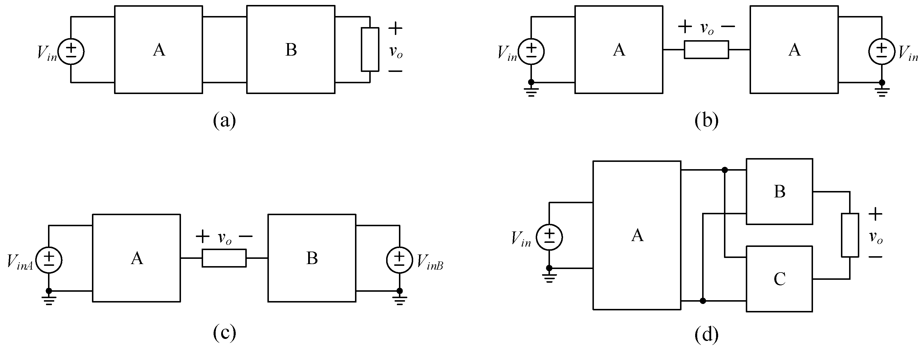
1. Introduction
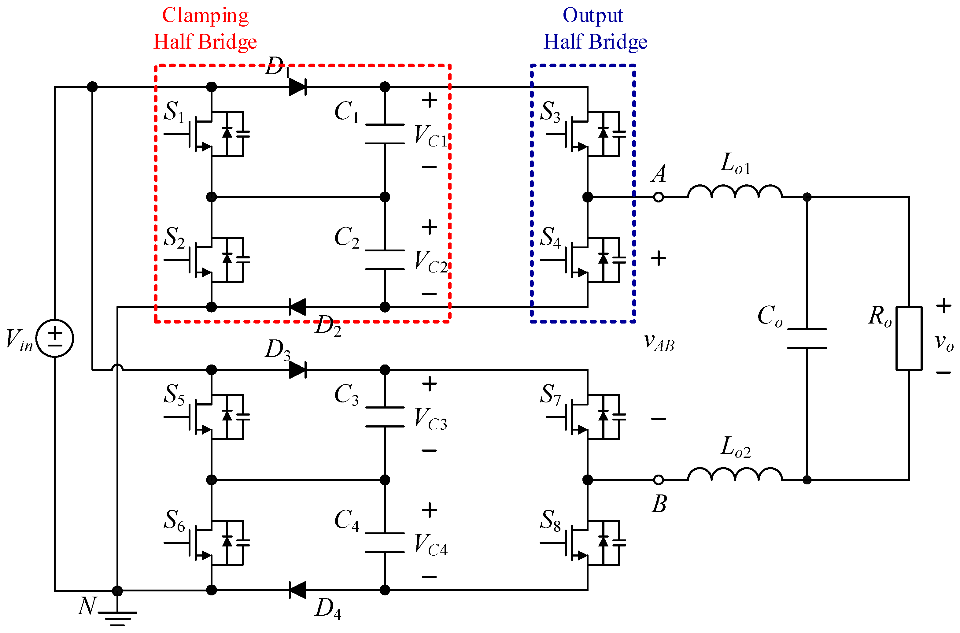
2. Introduction to the Proposed Circuit Structure
3. Operating Principle and Associated Analysis of the Proposed Inverter
3.1. Symbol Definitions and Assumptions
- (1)
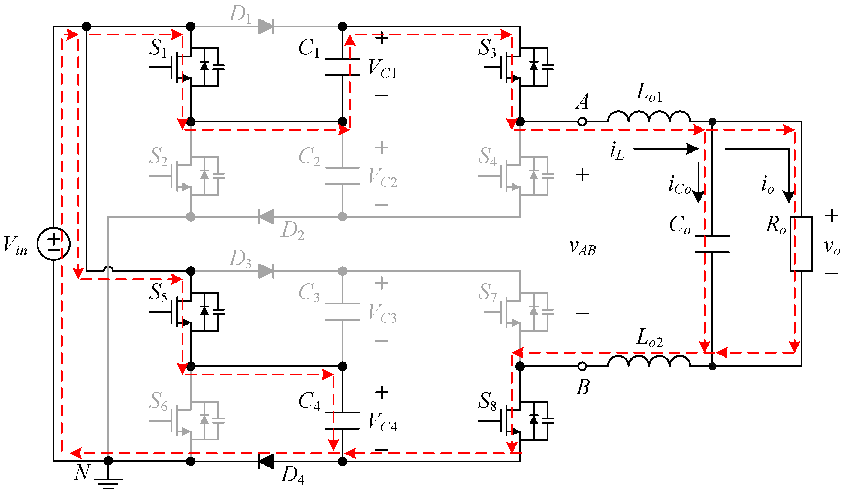
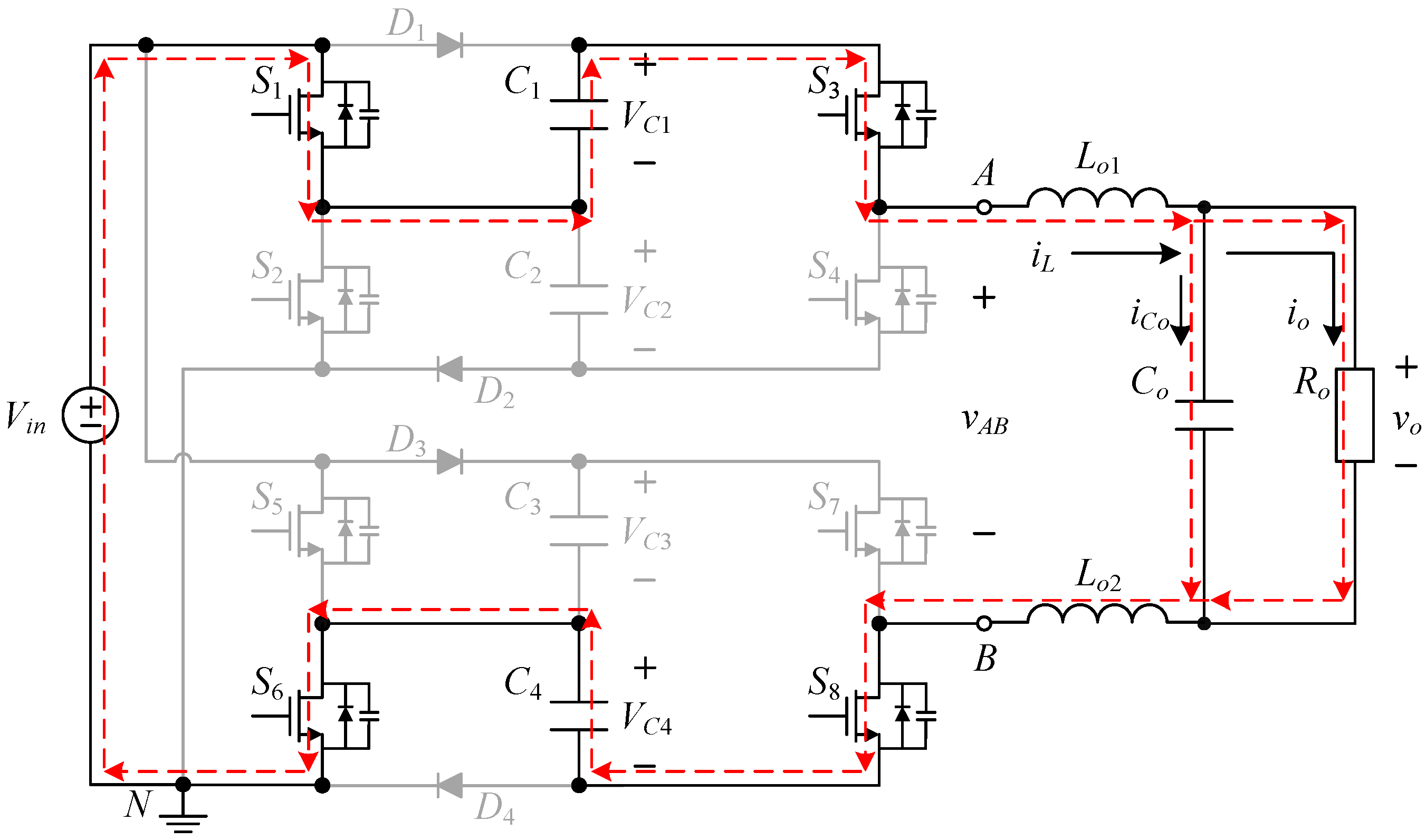
- Vin is the input voltage, vo is the output voltage, N is the reference point of zero potential, and Ro is the output resistor;
- (2)
- Lo1 and Lo2 are the filter inductors, Co is the filter capacitor, and C1 to C4 are the clamping capacitors;
- (3)
- iL is the current flowing through the filter inductors Lo1 and Lo2, iCo is the current flowing through the filter capacitor Co, and io is the output current;
- (4)
- S1 to S8 are the active switches and D1 to D4 are the passive switches;
- (5)
- By assuming that all the values of the clamping capacitors are large enough, the voltages across them can be viewed as constant, i.e., VC1 = VC2 = VC3 = VC4 = Vin;
- (6)
- It is assumed that all the components are regarded as ideal.
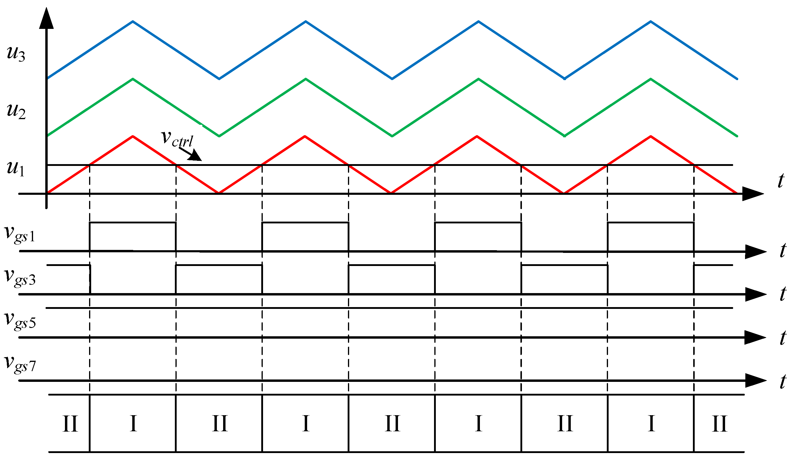
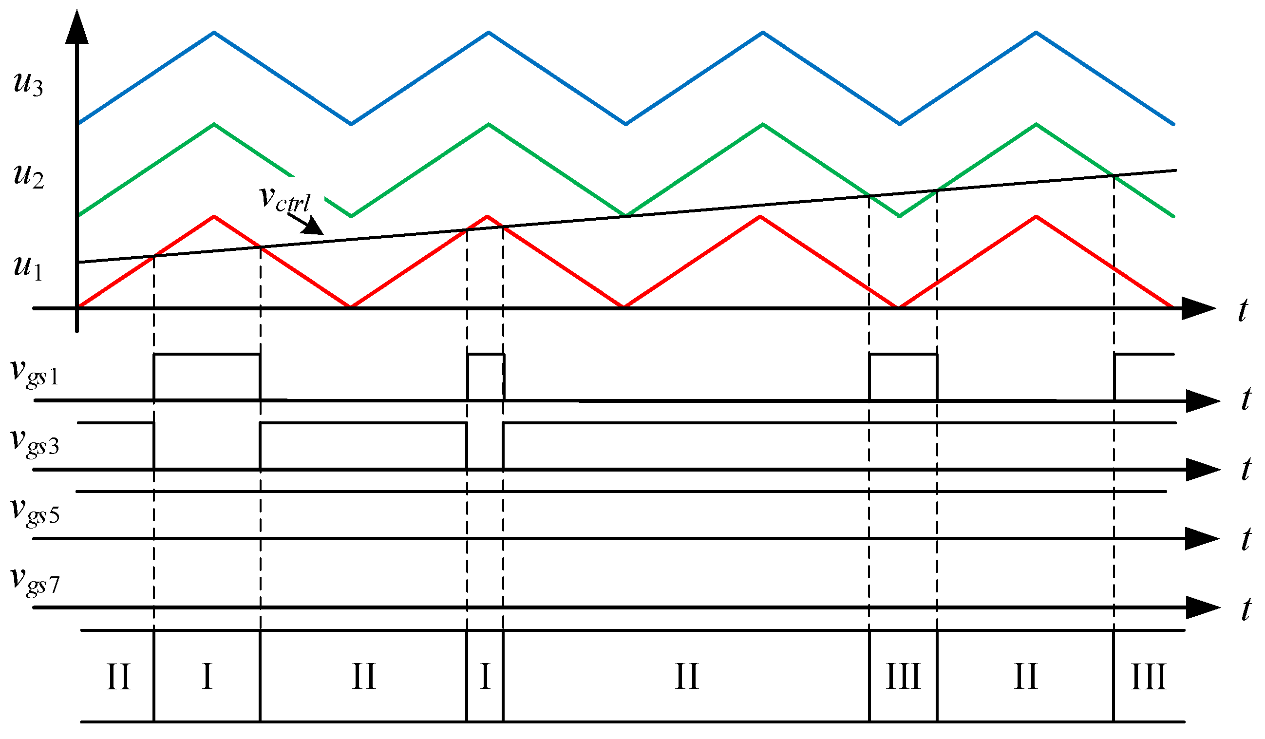
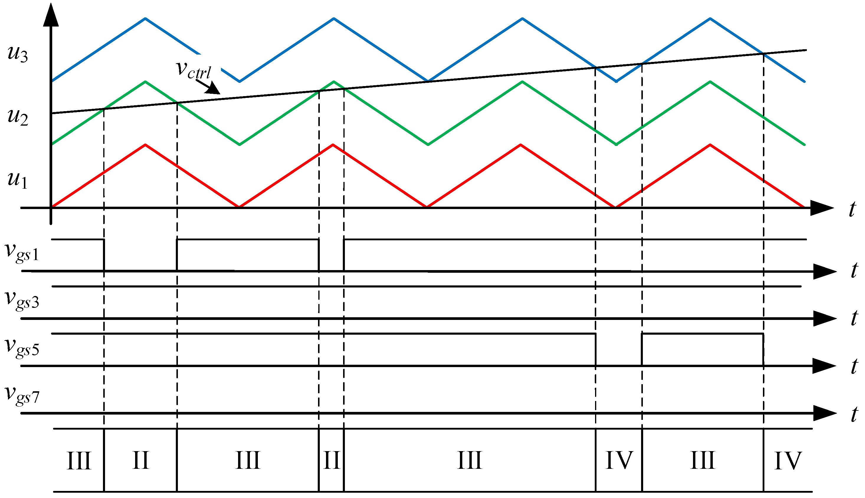
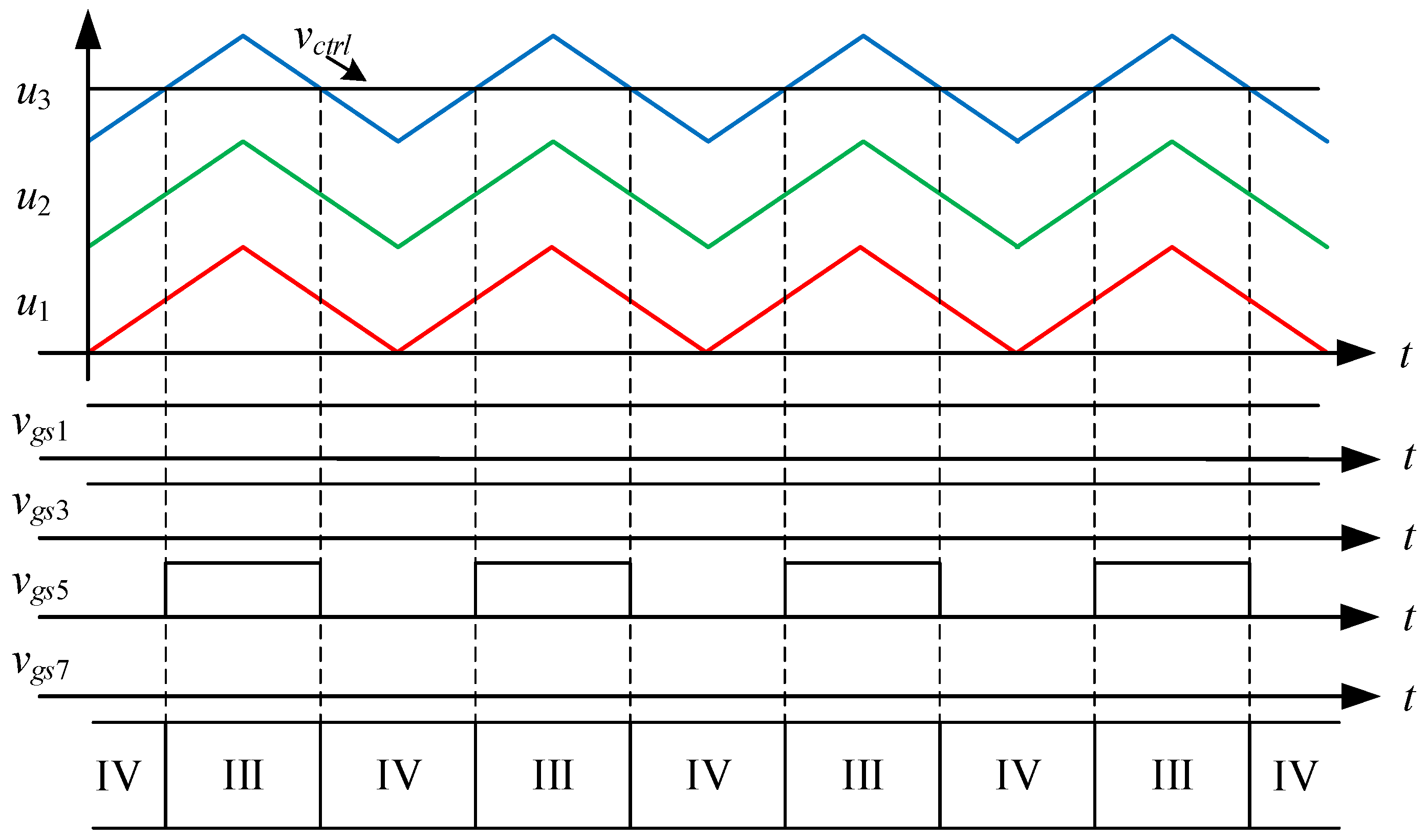
3.2. Operating Principle Analysis
3.3. Switch Behavior and Clamping Capacitor Behavior
4. Steady-State Analysis and Small-Signal Analysis
4.1. State-Space Averaging Model
4.2. Steady-State Analysis
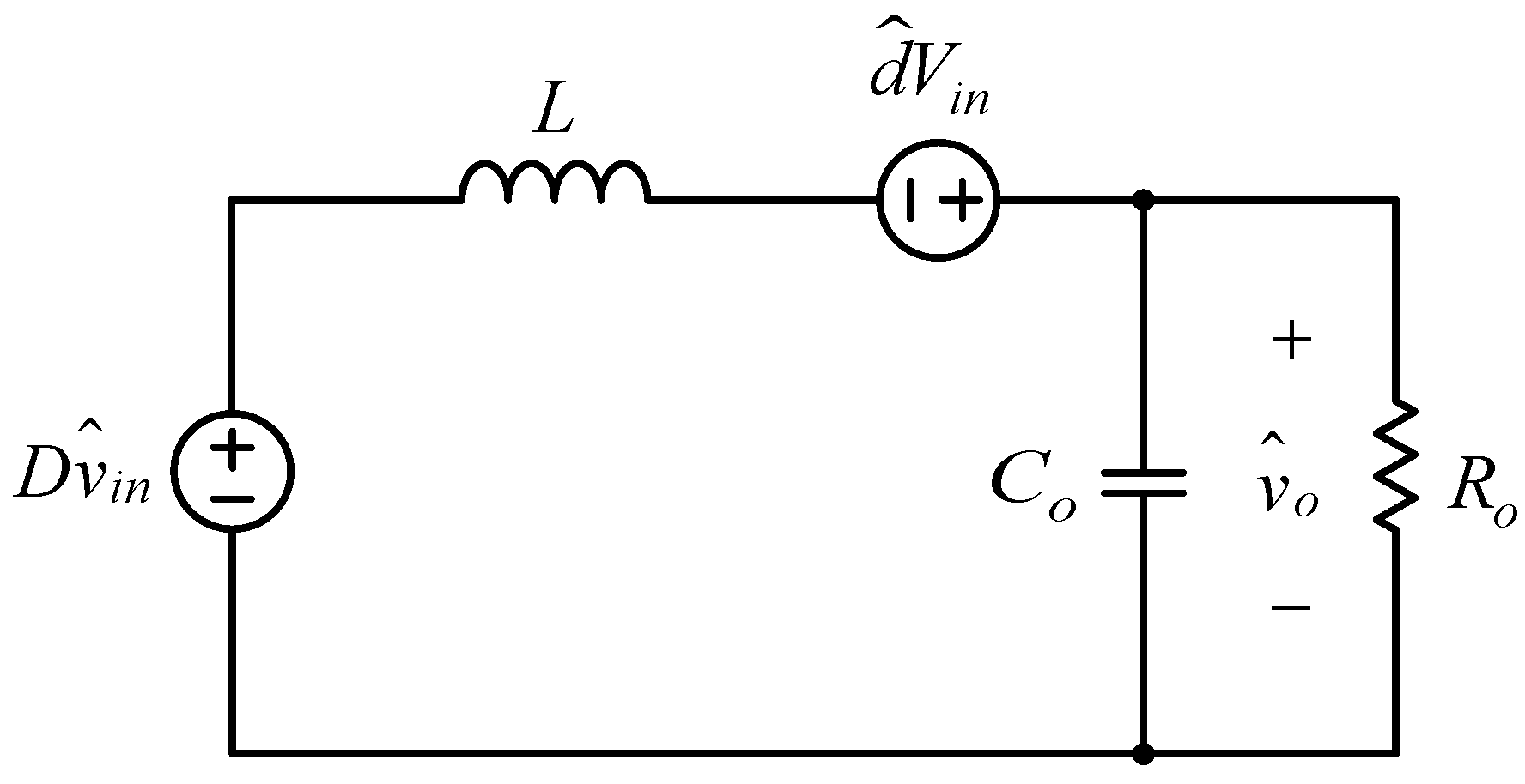
4.3. Small-Signal Analysis
5. Design Considerations
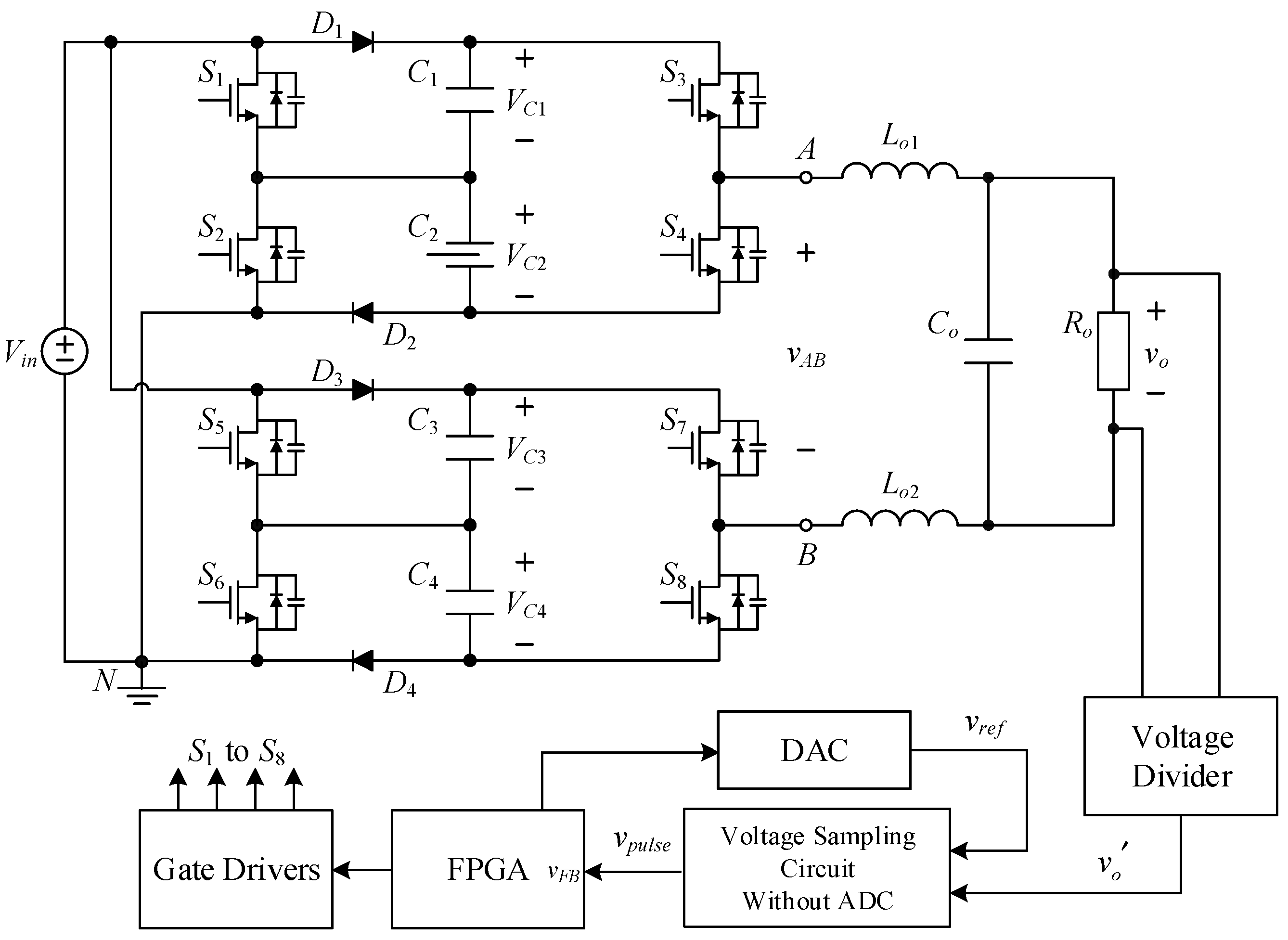
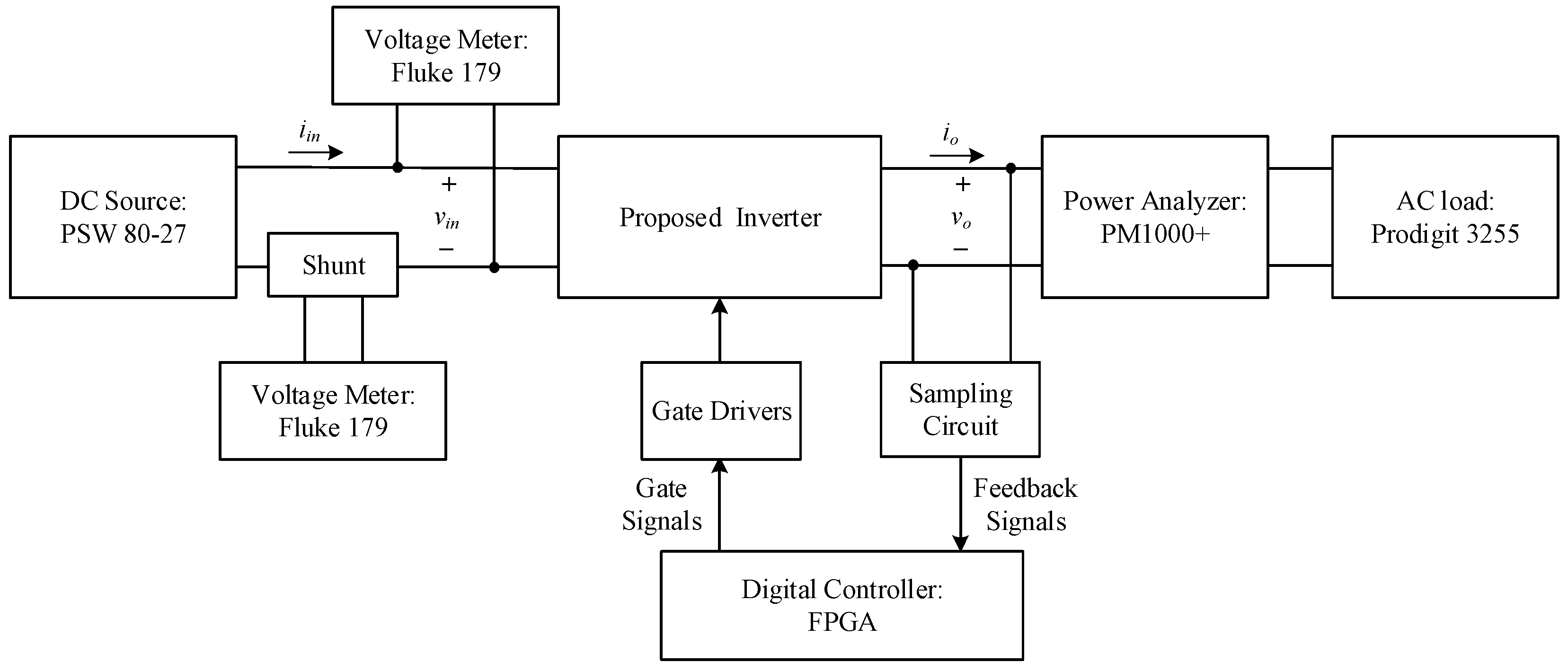
5.1. System Configuration
5.2. System Specifications
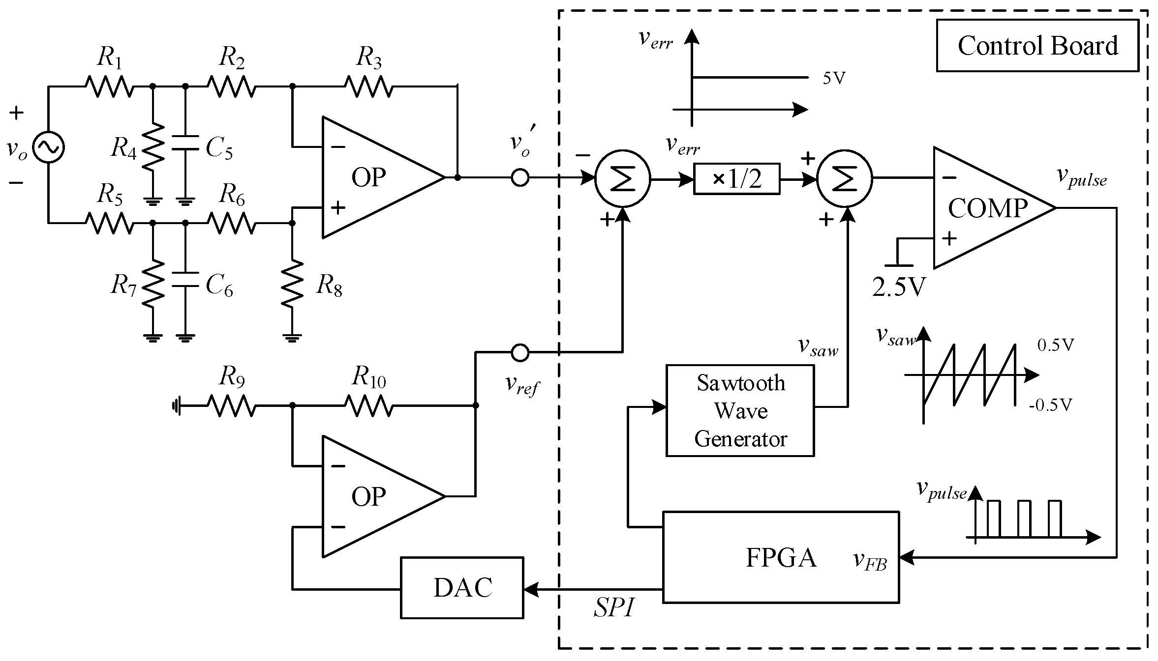
5.3. Controller Design
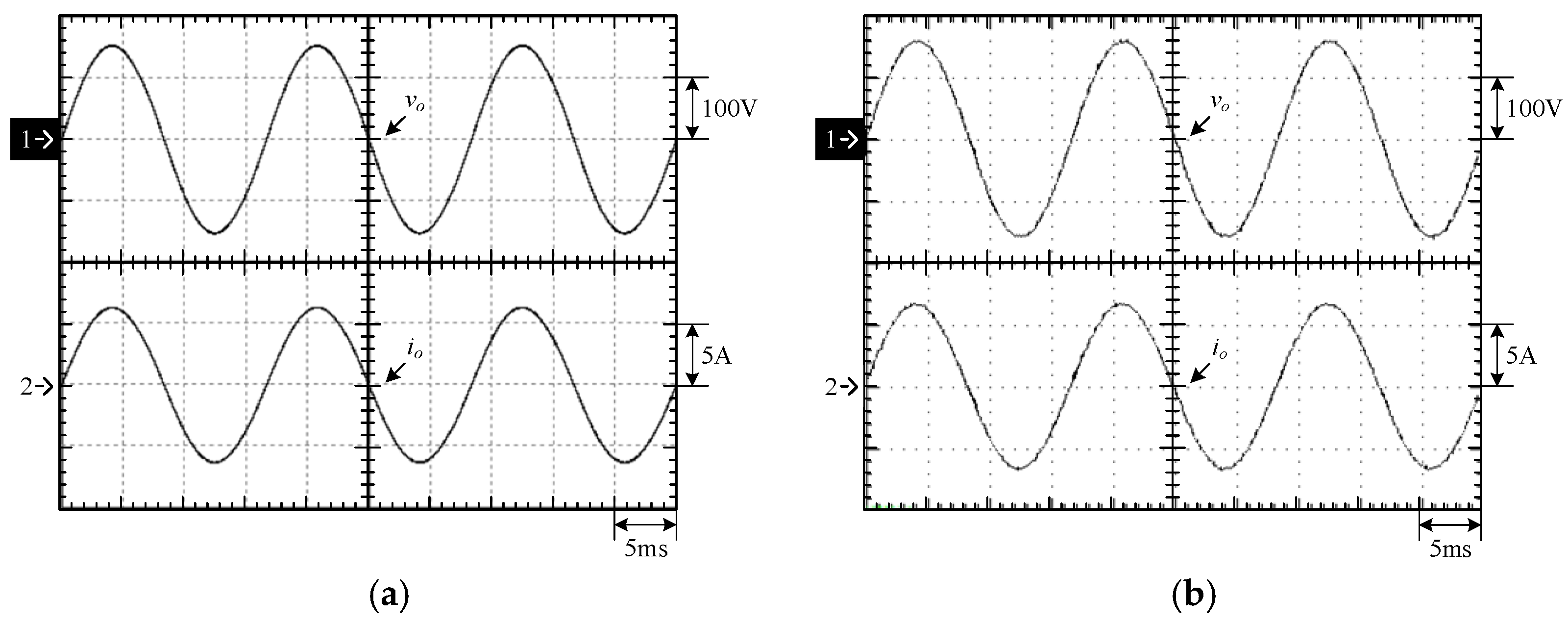
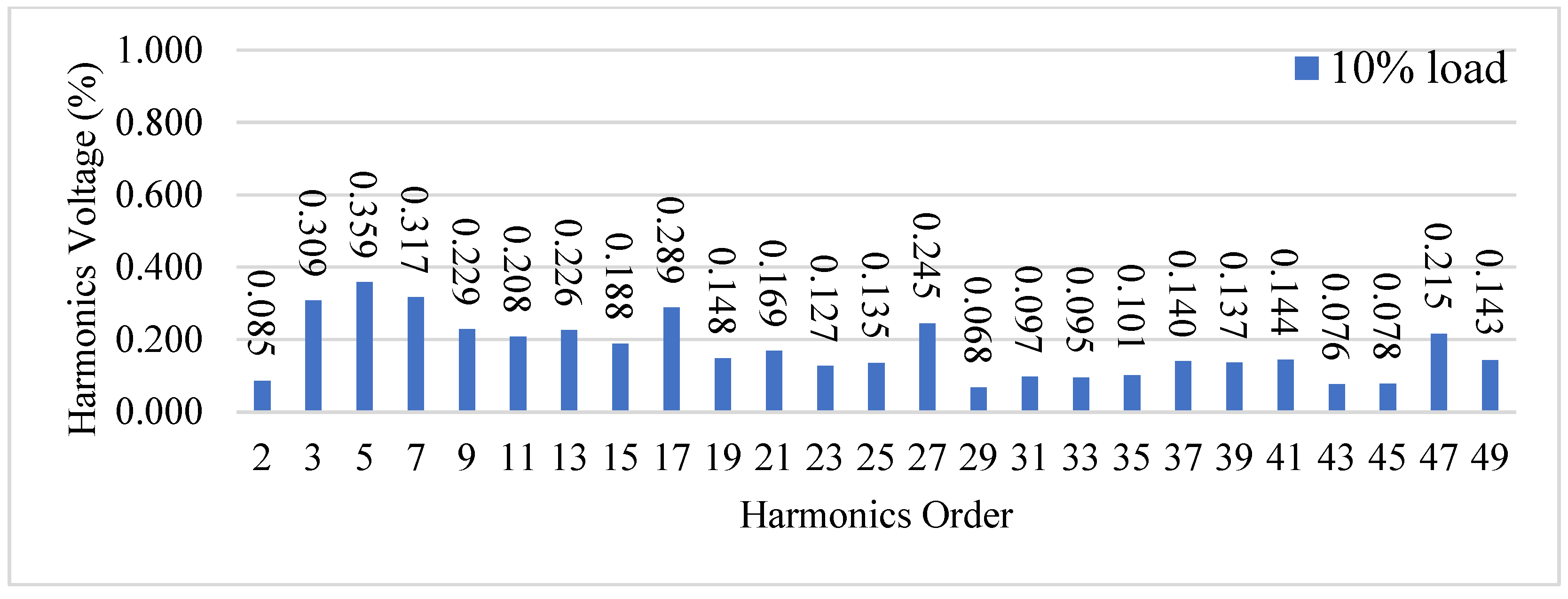
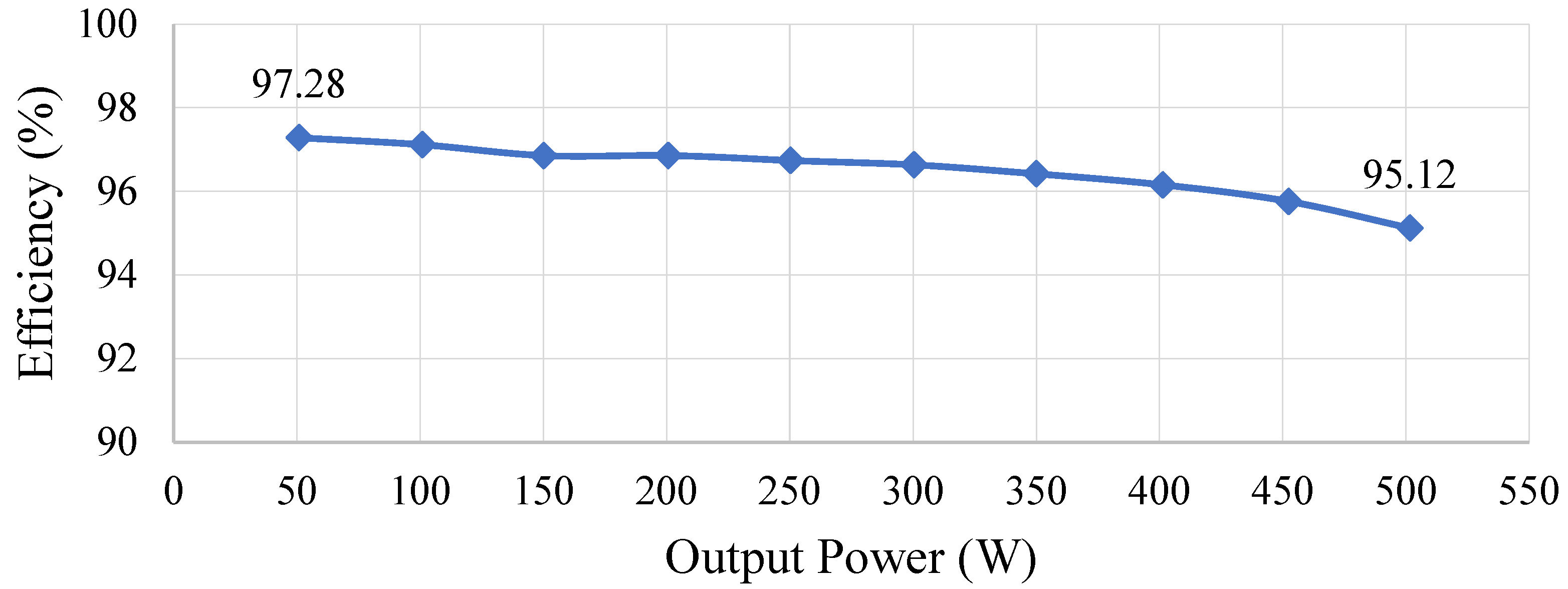
6. Simulated and Experimental Results
7. Conclusions
Author Contributions
Funding
Data Availability Statement
Conflicts of Interest
References
- Bp Statistical Review of World Energy 2022. Available online: https://www.bp.com/content/dam/bp/business-sites/en/global/corporate/pdfs/energy-economics/statistical-review/bp-stats-review-2022-full-report.pdf (accessed on 11 January 2023).
- IEEE 1547; Standard for Interconnection and Interoperability of Distributed Energy Resources with Associated Electric Power Systems Interfaces. IEEE Standards Association: Piscataway, NJ, USA, 2018.
- IEEE 519; Recommended Practices and Requirements for Harmonic Control in Electrical Power Systems. IEEE Standards Association: Piscataway, NJ, USA, 2014.
- IEC60038; Standard Voltages. IEEE Standards Association: Piscataway, NJ, USA, 2009.
- IEC61000-3-2; Electromagnetic Compatibility (EMC)-Part 3-2: Limits-Limits for Harmonic Current Emissions (Equipment Input Current ≤ 16 A per Phase). IEEE Standards Association: Piscataway, NJ, USA, 2005.
- IEC61000-3-3; Electromagnetic Compatibility (EMC)-Part 3-3: Limits-Limitation of Voltage Changes, Voltage Fluctuations and Flicker in Public Low-Voltage Supply Systems, for Equipment with Rated Current ≤ 16 A per Phase and Not Subject to Conditional Connection. IEEE Standards Association: Piscataway, NJ, USA, 2013.
- IEC62109-1; Safety of Power Converters for Use in Photovoltaic Power Systems-Part 1: General Requirements. IEEE Standards Association: Piscataway, NJ, USA, 2010.
- Koshti, A.K.; Rao, M.N. A brief review on multilevel inverter topologies. In Proceedings of the 2017 International Conference on Data Management, Analytics and Innovation (ICDMAI), Pune, India, 24–26 February 2017; pp. 1–7. [Google Scholar]
- Kumar, N.K.; Muthyala, U.R.; Dhabale, A. Optimized multilevel inverters derived from generalized asymmetrical topology. In Proceedings of the 2019 IEEE 4th International Future Energy Electronics Conference (IFEEC), Singapore, 24–28 November 2019; pp. 1–6. [Google Scholar]
- Priyadarshi, A.; Kar, P.K.; Karanki, S.B. A single source transformer-less boost multilevel inverter topology with self-voltage balancing. IEEE Trans. Ind. Appl. 2020, 56, 3954–3965. [Google Scholar] [CrossRef]
- Escobar, G.; Martinez-Garcia, J.F.; Vazquez-Guzman, G.; Martinez-Rodriguez, P.R.; Valdez-Fernandez, A.A.; Sosa-Zuniga, J.M. Step-up seven-level neutral-point-clamped inverter based topology for TL-PVS. IET Power Electron. 2020, 13, 2847–2853. [Google Scholar]
- Dargahi, V.; Abarzadeh, M.; Corzine, K.A.; Enslin, J.H.; Sadigh, A.K.; Rodriguez, J.; Blaabjerg, F.; Maqsood, A. Fundamental circuit topology of duo-active-neutral-point-clamped, duo-neutral-point-clamped, and duo-neutral-point-piloted multilevel converters. IEEE J. Emerg. Sel. Top. Power Electron. 2019, 7, 1224–1242. [Google Scholar] [CrossRef]
- Becker, F.; Jamshidpour, E.; Poure, P.; Saadate, S. Modulation strategy with a minimal number of commutations for a five-level H-bridge NPC inverter. Electronics 2019, 8, 454. [Google Scholar] [CrossRef]
- Stala1, R. Natural dc-link voltage balance in a single-phase npc inverter with four-level legs and novel modulation method. IET Power Electron. 2020, 13, 3764–3776. [Google Scholar] [CrossRef]
- Woldegiorgis, D.; Wei, Y.; Mhiesan, H.; Mantooth, A. New modulation technique for five-level interleaved T-type inverters for switching loss reduction. In Proceedings of the 2020 IEEE Energy Conversion Congress and Exposition (ECCE), Virtual, 11–15 October 2020; pp. 6253–6257. [Google Scholar]
- Meraj, S.T.; Hasan, K.; Masaoud, A. A novel configuration of cross-switched T-type (CT-type) multilevel inverter. IEEE Trans. Power Electron. 2020, 35, 3688–3696. [Google Scholar] [CrossRef]
- Odeh, C.I.; Lewicki, A.M.M.; Kondratenko, D. Three-level F-type inverter. IEEE Trans. Power Electron. 2021, 36, 11265–11275. [Google Scholar] [CrossRef]
- Batool, B.A.; Aliya; Noor, M.; Athar, S.O. A study of asymmetrical multilevel inverter topologies with less number of devices and low THD: A Review. In Proceedings of the 2018 International Conference on Power Generation Systems and Renewable Energy Technologies (PGSRET), Islamabad, Pakistan, 10–12 September 2018; pp. 1–6. [Google Scholar]
- Vu, T.T.; Beinarys, R. Feasibility study of compact high-efficiency bidirectional 3-level bridgeless totem-pole PFC/inverter at low cost. In Proceedings of the 2020 IEEE Applied Power Electronics Conference and Exposition (APEC), Long Beach, CA, USA, 15–19 March 2020; pp. 3397–3404. [Google Scholar]
- Lopez-Sanchez, M.J.; Pool, E.I.; Cruz-Chan, R.; Escobar, G.; Martinez-Garcia, J.F.; Valdez-Fernandez, A.A.; Villanueva, C. A single phase asymmetrical NPC inverter topology. In Proceedings of the 2016 13th International Conference on Power Electronics (CIEP), Guanajuato, Mexico, 20–23 June 2016. [Google Scholar]
- Woldegiorgis, D.; Mantooth, A. Five-level hybrid T-type inverter topology with mixed Si+SiC semiconductor device configuration. In Proceedings of the Thirtheenth Annual Energy Conversion Congress and Exposition, Vancouver, BC, Canada, 10–14 October 2021; pp. 991–996. [Google Scholar]
- Afjeh, M.G.; Babaei, M. Model predictive control of a modified five-level inverter with decreased device counts. Int. J. Circuit Theory Appl. 2021, 49, 1987–2006. [Google Scholar] [CrossRef]
- Choi, U.-M.; Lee, J.-S. Single-phase five-level IT-Type NPC Inverter with improved efficiency and reliability in photovoltaic systems. IEEE J. Emerg. Sel. Top. Power Electron. 2022, 10, 5226–5239. [Google Scholar] [CrossRef]
- Ye, M.; Wei, Q.; Li, S.; Ren, W.; Song, G. Research on balance control strategy of single capacitor clamped five-level inverter clamping capacitor. IET Power Electron. 2021, 14, 280–289. [Google Scholar] [CrossRef]
- Rao, B.N.; Suresh, Y.; Naik, B.S.; Venkataramanaiah, J.; Aditya, K.; Panda, A.K. A novel single source multilevel inverter with hybrid switching technique. Int. J. Circuit Theory Appl. 2021, 50, 794–811. [Google Scholar]
- Sun, X.; Yun, Z. Hybrid control strategy for a novel asymmetrical multilevel inverter. In Proceedings of the 2010 International Conference on Intelligent System Design and Engineering Application (ISDEA), Changsha, China, 13–14 October 2010; pp. 1–8. [Google Scholar]
- Abu Sneineh, A.; Wang, M.-Y. Novel hybrid flying-capacitor-half-bridge 9-level inverter. In Proceedings of the TENCON 2006—2006 IEEE Region 10 Conference, Hong Kong, China, 14–17 November 2006; pp. 1–4. [Google Scholar]
- Tayyab, M.; Sarwar, A.; Murshid, S.; Tariq, M.; Al-Durra, A.; Bakhsh, F.I. Active and reactive power control of grid-connected single-phase asymmetrical eleven-level inverter. IET Gener. Transm. Distrib. 2022, 17, 632–644. [Google Scholar] [CrossRef]
- Erickson, R.W.; Maksimovic, D. Fundamental Power Electronics, 2nd ed.; Electronic Services: London, UK, 2001. [Google Scholar]
- Hwu, K.I.; Yau, Y.T. Applying one-comparator counter-based PWM control strategy to DC-AC converter with voltage reference feedforward control considered. In Proceedings of the 2011 IEEE Applied Power Electronics Conference and Exposition—APEC 2011, Fort Worth, TX, USA, 6–11 March 2011; pp. 1811–1815. [Google Scholar]
- Phillips, C.L.; Nagle, H.T. Digital Control System Analysis and Design, 4th ed.; Prentice-Hall Inc.: Raleigh, NC, USA, 2015. [Google Scholar]


| States | Switches | Capacitors | vAN | vBN | vAB | ||||||||||
|---|---|---|---|---|---|---|---|---|---|---|---|---|---|---|---|
| S1 | S2 | S3 | S4 | S5 | S6 | S7 | S8 | C1 | C2 | C3 | C4 | ||||
| I | 1 | 0 | 0 | 1 | 1 | 0 | 0 | 1 | --- | C | --- | C | 0 Vin | 0 Vin | 0 Vin |
| II | 0 | 1 | 1 | 0 | 1 | 0 | 0 | 1 | C | --- | --- | C | 1 Vin | 0 | 1 Vin |
| III | 1 | 0 | 1 | 0 | 1 | 0 | 0 | 1 | D | --- | --- | C | 2 Vin | 0 | 2 Vin |
| IV | 1 | 0 | 1 | 0 | 0 | 1 | 0 | 1 | D | --- | --- | D | 2 Vin | −1 Vin | 3 Vin |
| V | 1 | 0 | 0 | 1 | 0 | 1 | 1 | 0 | --- | C | --- | C | 0 Vin | 1 Vin | −1 Vin |
| VI | 1 | 0 | 0 | 1 | 1 | 0 | 1 | 0 | --- | C | --- | C | 0 Vin | 2 Vin | −2 Vin |
| VII | 0 | 1 | 0 | 1 | 1 | 0 | 1 | 0 | --- | --- | D | D | −1 Vin | 2 Vin | −3 Vin |
| Specification/Component | Model Name/Value |
|---|---|
| DC Input Voltage (Vin) | 58 V |
| AC Output Voltage (vo) | 110 Vrms |
| Output Frequency (fline) | 60 Hz |
| Rated Power (Po,rated) | 500 W |
| Clamped Capacitors (C1 to C4) | 3.3 mF/100 V |
| Output Filter Capacitor (Co) | 1 μF/275 V (MKP) |
| Output filter Inductors (Lo1 and Lo2) | 142 μH (Ring Core) |
| Switching Frequency (fs) | 58.6 kHz |
| Geometric Type | Component Symbol | Model Name/Value |
|---|---|---|
| Four-Channel OPA | OP | TLV2374 |
| Dip Resistors | R1 and R5 | 100 kΩ |
| SMD 0805 Resistors | R2 and R6 | 115 kΩ |
| SMD 0805 Resistors | R3 and R8 | 18.2 kΩ |
| SMD 0805 Resistors | R4 and R7 | 10.5 kΩ |
| SMD 0805 Resistors | R9 and R10 | 2 kΩ |
| 0805 MLCC | C5 and C6 | 10 nF |
Disclaimer/Publisher’s Note: The statements, opinions and data contained in all publications are solely those of the individual author(s) and contributor(s) and not of MDPI and/or the editor(s). MDPI and/or the editor(s) disclaim responsibility for any injury to people or property resulting from any ideas, methods, instructions or products referred to in the content. |
© 2024 by the authors. Licensee MDPI, Basel, Switzerland. This article is an open access article distributed under the terms and conditions of the Creative Commons Attribution (CC BY) license (https://creativecommons.org/licenses/by/4.0/).
Share and Cite
Shieh, J.-J.; Hwu, K.-I.; Chen, S.-J. High-Performance Multi-Level Inverter with Symmetry and Simplification. Micromachines 2024, 15, 766. https://doi.org/10.3390/mi15060766
Shieh J-J, Hwu K-I, Chen S-J. High-Performance Multi-Level Inverter with Symmetry and Simplification. Micromachines. 2024; 15(6):766. https://doi.org/10.3390/mi15060766
Chicago/Turabian StyleShieh, Jenn-Jong, Kuo-Ing Hwu, and Sheng-Ju Chen. 2024. "High-Performance Multi-Level Inverter with Symmetry and Simplification" Micromachines 15, no. 6: 766. https://doi.org/10.3390/mi15060766
APA StyleShieh, J.-J., Hwu, K.-I., & Chen, S.-J. (2024). High-Performance Multi-Level Inverter with Symmetry and Simplification. Micromachines, 15(6), 766. https://doi.org/10.3390/mi15060766