
Influence of Active-to-Passive Ratio on the Deformation in Circular Dielectric Elastomer Actuators

 , , , and
Abstract
1. Introduction
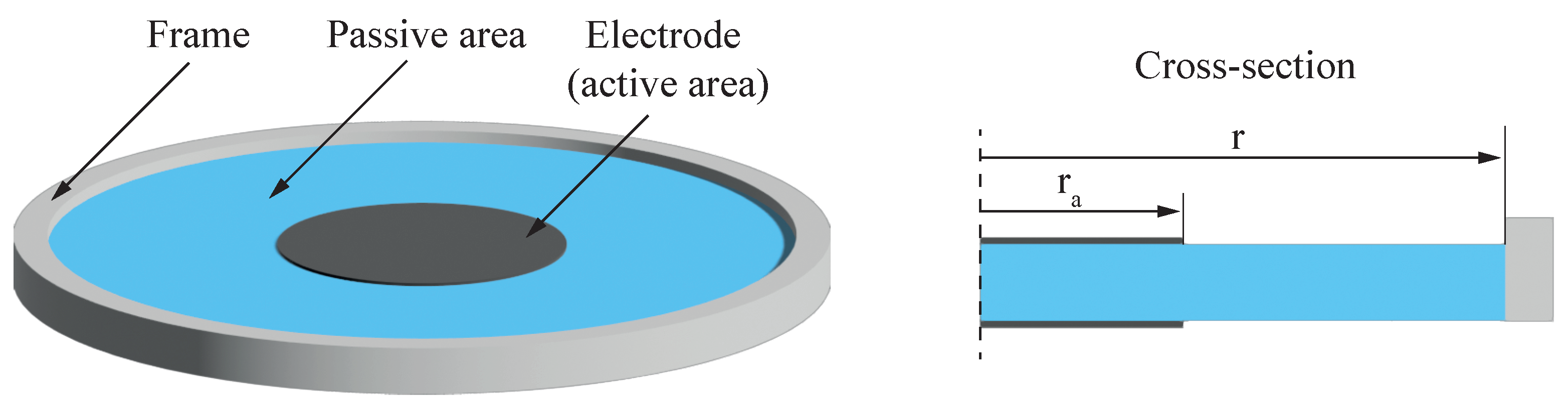
2. Modeling
- incompressibility of the dielectric material (),
- independence of the relative permittivity from material strain,
- negligible impact of electrodes on mechanical stiffness and
- homogeneity of the electric field E.
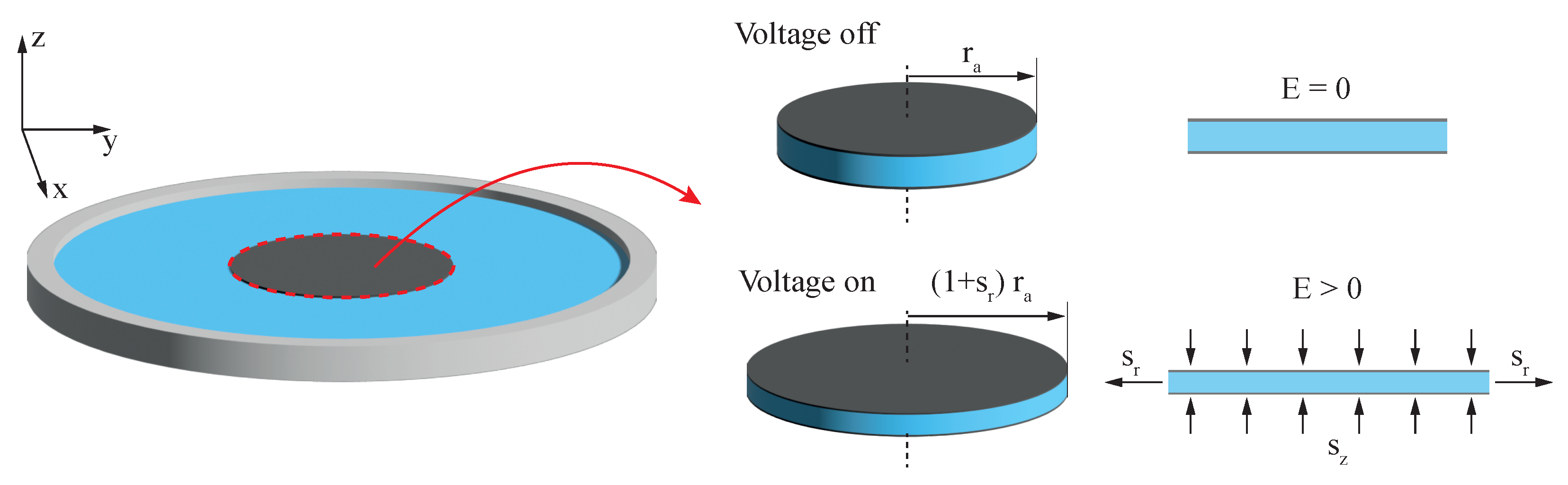
2.1. Pelrine Approach
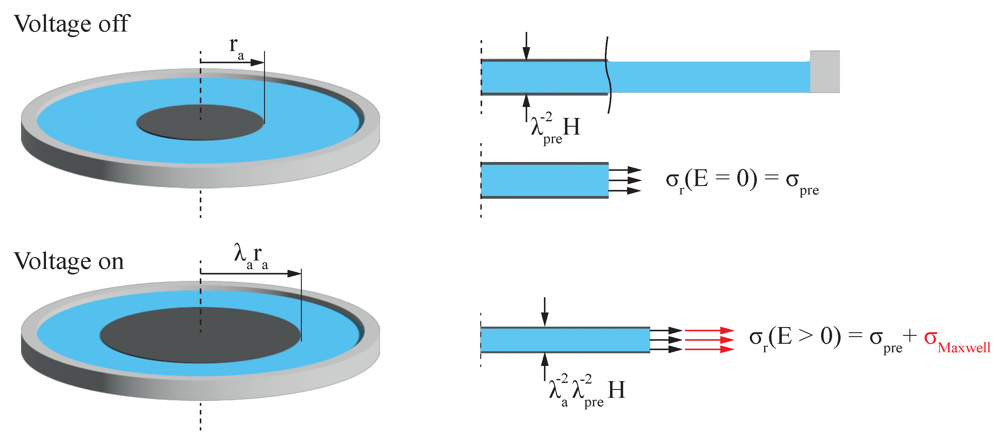
2.2. Hyperelastic Membrane under Constant Equi-Biaxial Force
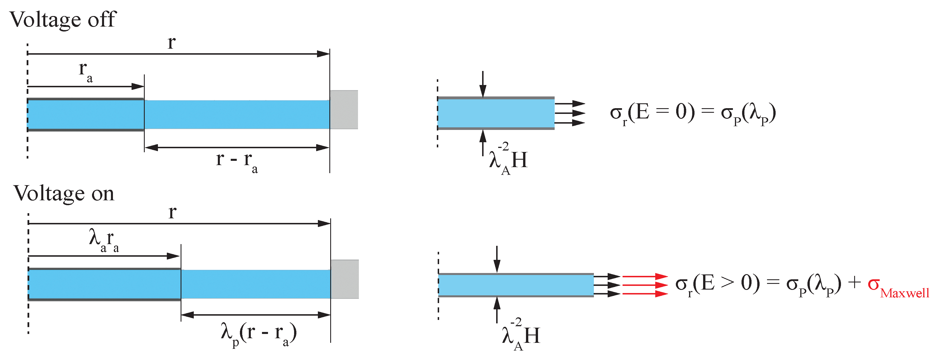
2.3. Hypereleastic Membrane under Equi-Biaxial Forces Considering Coverage Ratio
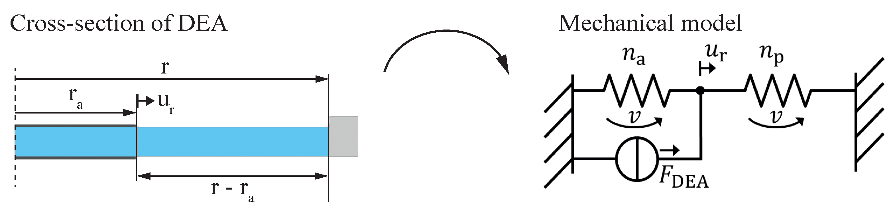
2.4. Linear Elastic Lumped Parameter Model
3. Experimental Validation
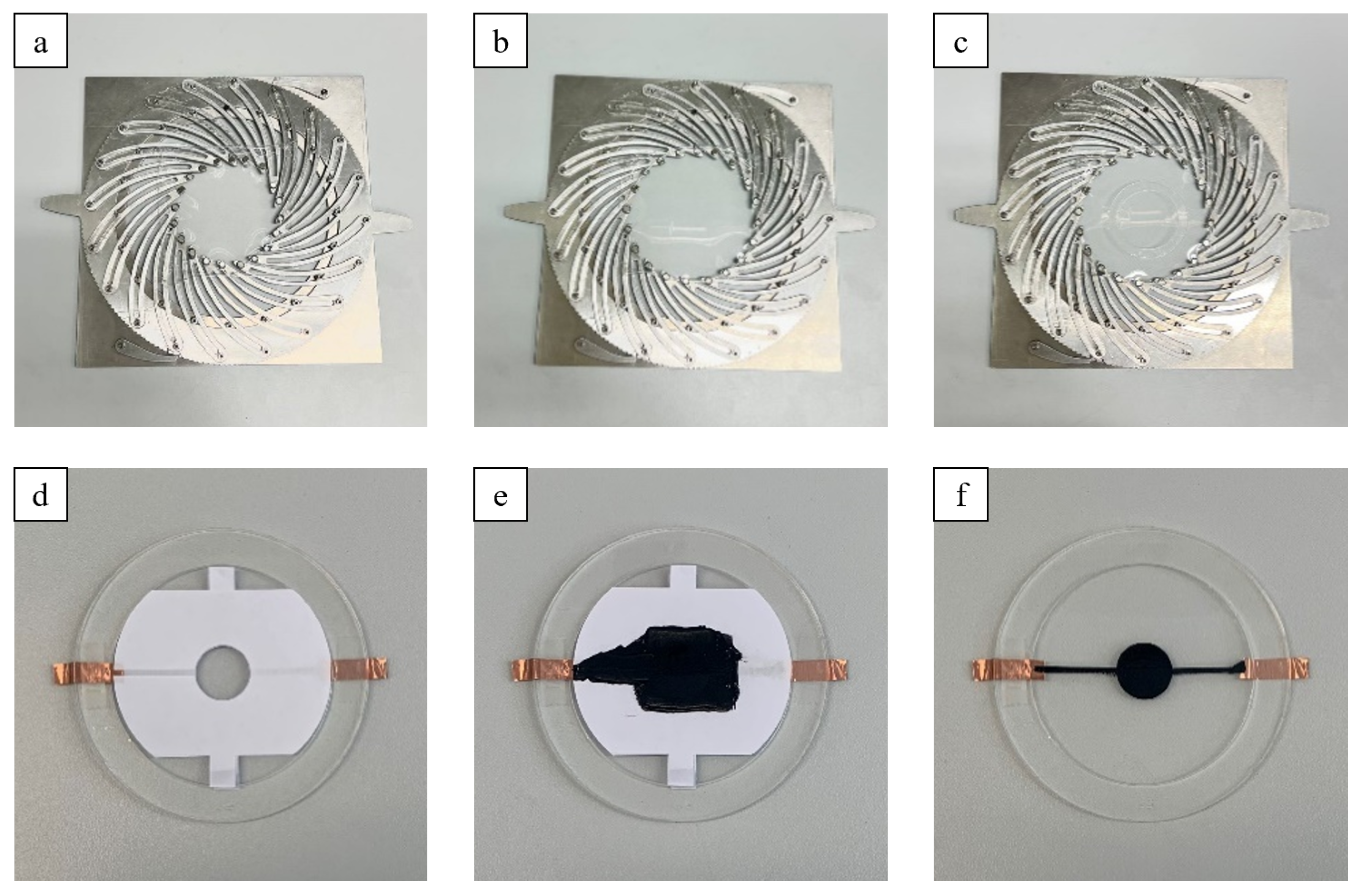
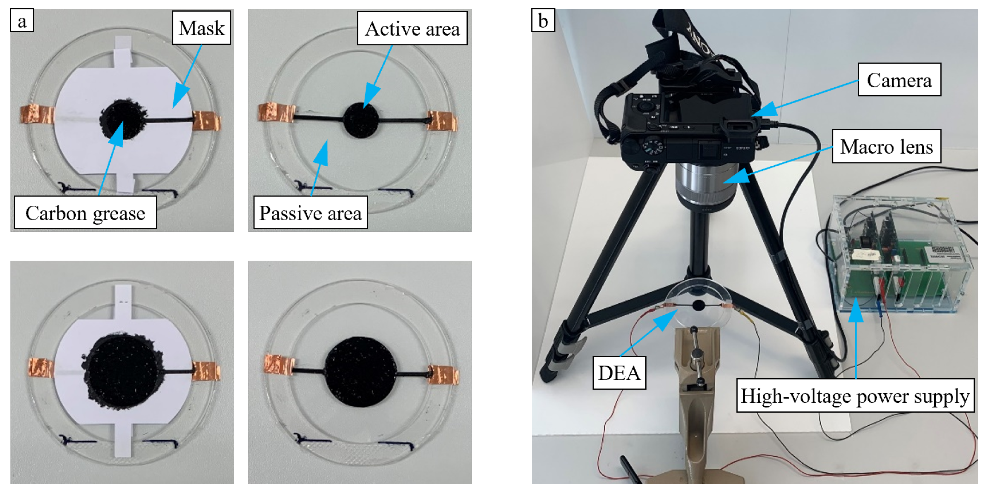
3.1. Manufacturing of the Actuators
3.2. Electro-Mechanical Characterization
4. Results
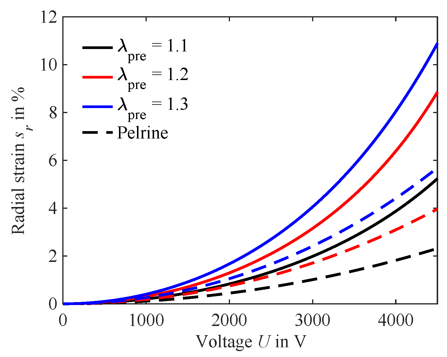
4.1. Model Results
4.2. Experimental Results
5. Discussion
6. Conclusions
Author Contributions
Funding
Data Availability Statement
Acknowledgments
Conflicts of Interest
Abbreviations
| DEA | Dielctric elastomer actuator |
| DE | Dielectric elastomer |
References
- Pelrine, R.E.; Kornbluh, R.D.; Joseph, J.P. Electrostriction of polymer dielectrics with compliant electrodes as a means of actuation. Sens. Actuators A Phys. 1998, 64, 77–85. [Google Scholar] [CrossRef]
- Pelrine, R.; Kornbluh, R.; Pei, Q.; Joseph, J. High-Speed Electrically Actuated Elastomers with Strain Greater Than 100%. Science 2000, 287, 836–839. [Google Scholar] [CrossRef] [PubMed]
- Huang, J.; Li, T.; Foo, C.C.; Zhu, J.; Clarke, D.R.; Suo, Z. Giant, voltage-actuated deformation of a dielectric elastomer under dead load. Appl. Phys. Lett. 2012, 100, 041911. [Google Scholar] [CrossRef]
- Koenigsdorff, M.; Mersch, J.; Pfeil, S.; Gerlach, G. Anisotropic carbon fibre electrodes for dielectric elastomer actuators. In Proceedings of the International Conference and Exhibition on New Actuator Systems and Applications, Mannheim, Germany, 29–30 June 2022; pp. 1–4. [Google Scholar]
- Hau, S.; Bruch, D.; Rizzello, G.; Motzki, P.; Seelecke, S. Silicone based dielectric elastomer strip actuators coupled with nonlinear biasing elements for large actuation strains. Smart Mater. Struct. 2018, 27, 074003. [Google Scholar] [CrossRef]
- Hodgins, M.; York, A.; Seelecke, S. Experimental comparison of bias elements for out-of-plane DEAP actuator system. Smart Mater. Struct. 2013, 22, 094016. [Google Scholar] [CrossRef]
- Liebscher, H.; Suresh, J.N.; Koenigsdorff, M.; Tahir, M.; Wiesner, S.; Gerlach, G. Comparative study of barium titanate-filled polyurethane and hydrogenated nitrile butadiene rubber as electroactive polymer composites. In Proceedings of the International Workshop on Impedance Spectroscopy, IWIS 2022, Chemnitz, Germany, 27–30 September 2022; pp. 79–84. [Google Scholar] [CrossRef]
- Koenigsdorff, M.; Liebscher, H.; Endesfelder, A.; Zhang, Q.; Zimmermann, M.; Gerlach, G. Effect of Barium Titanate Particle Filler in Soft Silicone Films on their Application in Dielectric Elastomer Actuators. In Proceedings of the 2022 International Workshop on Impedance Spectroscopy (IWIS), Chemnitz, Germany, 27–30 September 2022; pp. 88–91. [Google Scholar] [CrossRef]
- Carpi, F.; Anderson, I.; Bauer, S.; Frediani, G.; Gallone, G.; Gei, M.; Graaf, C.; Jean-Mistral, C.; Kaal, W.; Kofod, G.; et al. Standards for dielectric elastomer transducers. Smart Mater. Struct. 2015, 24, 105025. [Google Scholar] [CrossRef]
- Liebscher, H.; Suresh, J.N.; Li, H.; Mersch, J.; Wießner, S.; Gerlach, G. Humidity Dependence of the Dielectric Constant of a Thermosetting Polyurethane. In Proceedings of the 2023 International Workshop on Impedance Spectroscopy (IWIS), Chemnitz, Germany, 26–29 September 2023; pp. 63–66. [Google Scholar]
- Tran, D.Q.; Li, J.; Xuan, F.; Xiao, T. Viscoelastic effects on the actuation performance of a dielectric elastomer actuator under different equal, un-equal biaxial pre-stretches. Mater. Res. Express 2018, 5, 065303. [Google Scholar] [CrossRef]
- Sahu, D.; Sahu, R.K.; Patra, K. In–plane actuation performance of graphene oxide filled VHB 4910 dielectric elastomer. J. Appl. Polym. Sci. 2022, 139, 51594. [Google Scholar] [CrossRef]
- Yin, L.J.; Zhao, Y.; Zhu, J.; Yang, M.; Zhao, H.; Pei, J.Y.; Zhong, S.L.; Dang, Z.M. Soft, tough, and fast polyacrylate dielectric elastomer for non-magnetic motor. Nat. Commun. 2021, 12, 4517. [Google Scholar] [CrossRef]
- Lee, Y.R.; Kwon, H.; Lee, D.H.; Lee, B.Y. Highly flexible and transparent dielectric elastomer actuators using silver nanowire and carbon nanotube hybrid electrodes. Soft Matter 2017, 13, 6390–6395. [Google Scholar] [CrossRef]
- Wissler, M.; Mazza, E. Mechanical behavior of an acrylic elastomer used in dielectric elastomer actuators. Sens. Actuators A Phys. 2007, 134, 494–504. [Google Scholar] [CrossRef]
- Pieroni, M.; Lagomarsini, C.; De Rossi, D.; Carpi, F. Electrically tunable soft solid lens inspired by reptile and bird accommodation. Bioinspir. Biomim. 2016, 11, 065003. [Google Scholar] [CrossRef] [PubMed]
- Maffli, L.; Rosset, S.; Ghilardi, M.; Carpi, F.; Shea, H. Ultrafast all-polymer electrically tunable silicone lenses. Adv. Funct. Mater. 2015, 25, 1656–1665. [Google Scholar] [CrossRef]
- Suo, Z. Theory of dielectric elastomers. Acta Mech. Solida Sin. 2010, 23, 549–578. [Google Scholar] [CrossRef]
- Yeoh, O.H. Characterization of elastic properties of carbon-black-filled rubber vulcanizates. Rubber Chem. Technol. 1990, 63, 792–805. [Google Scholar] [CrossRef]
- Koh, S.J.A.; Li, T.; Zhou, J.; Zhao, X.; Hong, W.; Zhu, J.; Suo, Z. Mechanisms of large actuation strain in dielectric elastomers. J. Polym. Sci. Part B Polym. Phys. 2011, 49, 504–515. [Google Scholar] [CrossRef]
- Liebscher, H.; Endesfelder, A.; Koenigsdorff, M.; Mersch, J.; Zimmermann, M.; Gerlach, G. Influence of the active-to-passive area ratio on the electrically induced strain of a fiber-reinforced dielectric elastomer actuator. In Proceedings of the Electroactive Polymer Actuators and Devices (EAPAD) XXV, Long Beach, CA, USA, 12–17 March 2023; Madden, J.D., Anderson, I.A., Shea, H.R., Eds.; SPIE: Bellingham, WA, USA, 2023; pp. 257–264. [Google Scholar] [CrossRef]
- Liebscher, H.; Koenigsdorff, M.; Endesfelder, A.; Mersch, J.; Zimmermann, M.; Gerlach, G. Understanding the Impact of Active-to-Passive Area Ratio on Deformation in One-Dimensional Dielectric Elastomer Actuators with Uniaxial Strain State. Materials 2023, 16, 6897. [Google Scholar] [CrossRef]
- Schlatter, S.; Illenberger, P.; Rosset, S. Peta-pico-Voltron: An open-source high voltage power supply. HardwareX 2018, 4, e00039. [Google Scholar] [CrossRef]
- Boyce, M.C.; Arruda, E.M. Constitutive Models of Rubber Elasticity: A Review. Rubber Chem. Technol. 2000, 73, 504–523. [Google Scholar] [CrossRef]
- Rosset, S.; Maffli, L.; Houis, S.; Shea, H.R. An instrument to obtain the correct biaxial hyperelastic parameters of silicones for accurate DEA modelling. In Proceedings of the Electroactive Polymer Actuators and Devices (EAPAD), San Diego, CA, USA, 9–13 March 2014; Bar-Cohen, Y., Ed.; International Society for Optics and Photonics (SPIE): Bellingham, WA, USA, 2014; Volume 9056, p. 90560M. [Google Scholar] [CrossRef]
- Shian, S.; Diebold, R.M.; Clarke, D.R. Tunable lenses using transparent dielectric elastomer actuators. Opt. Express 2013, 21, 8669–8676. [Google Scholar] [CrossRef]
- Martin, S.; Schwab, J.; López, P.C.; Benke, E.; Reitelshöfer, S.; Franke, J. Mechanical modifications of soft actuators for the use as a dynamic iris implant. In Proceedings of the 2021 43rd Annual International Conference of the IEEE Engineering in Medicine & Biology Society (EMBC), Mexico City, Mexico, 1–5 November 2021; pp. 4709–4712. [Google Scholar] [CrossRef]
- Mersch, J.; Bruns, M.; Nocke, A.; Cherif, C.; Gerlach, G. High-displacement, fiber-reinforced shape memory alloy soft actuator with integrated sensors and its equivalent network model. Adv. Intell. Syst. 2021, 3, 2000221. [Google Scholar] [CrossRef]


| Study | Electrode Radius (mm) | Total DE Radius (mm) | Coverage Ratio |
|---|---|---|---|
| Wissler and Mazza [15] | 7.5 | 75 | 0.1 |
| Lee et al. [14] | 15 | 48 | 0.3125 |
| Yin et al. [13] | 25 | 120 | 0.2083 |
| Sahu et al. [12] | 25 | 100 | 0.25 |
| Yeoh Parameter | Fit Value (Pa) |
|---|---|
| 178,426 | |
| −6023 | |
| 4234 |
Disclaimer/Publisher’s Note: The statements, opinions and data contained in all publications are solely those of the individual author(s) and contributor(s) and not of MDPI and/or the editor(s). MDPI and/or the editor(s) disclaim responsibility for any injury to people or property resulting from any ideas, methods, instructions or products referred to in the content. |
© 2024 by the authors. Licensee MDPI, Basel, Switzerland. This article is an open access article distributed under the terms and conditions of the Creative Commons Attribution (CC BY) license (https://creativecommons.org/licenses/by/4.0/).
Share and Cite
Koenigsdorff, M.; Liebscher, H.; Osipov, P.; Mersch, J.; Gerlach, G. Influence of Active-to-Passive Ratio on the Deformation in Circular Dielectric Elastomer Actuators. Micromachines 2024, 15, 125. https://doi.org/10.3390/mi15010125
Koenigsdorff M, Liebscher H, Osipov P, Mersch J, Gerlach G. Influence of Active-to-Passive Ratio on the Deformation in Circular Dielectric Elastomer Actuators. Micromachines. 2024; 15(1):125. https://doi.org/10.3390/mi15010125
Chicago/Turabian StyleKoenigsdorff, Markus, Hans Liebscher, Petr Osipov, Johannes Mersch, and Gerald Gerlach. 2024. "Influence of Active-to-Passive Ratio on the Deformation in Circular Dielectric Elastomer Actuators" Micromachines 15, no. 1: 125. https://doi.org/10.3390/mi15010125
APA StyleKoenigsdorff, M., Liebscher, H., Osipov, P., Mersch, J., & Gerlach, G. (2024). Influence of Active-to-Passive Ratio on the Deformation in Circular Dielectric Elastomer Actuators. Micromachines, 15(1), 125. https://doi.org/10.3390/mi15010125