
Implementation of Wavelet-Transform-Based Algorithms in an FPGA for Heart Rate and RT Interval Automatic Measurements in Real Time: Application in a Long-Term Ambulatory Electrocardiogram Monitor


Abstract
:1. Introduction
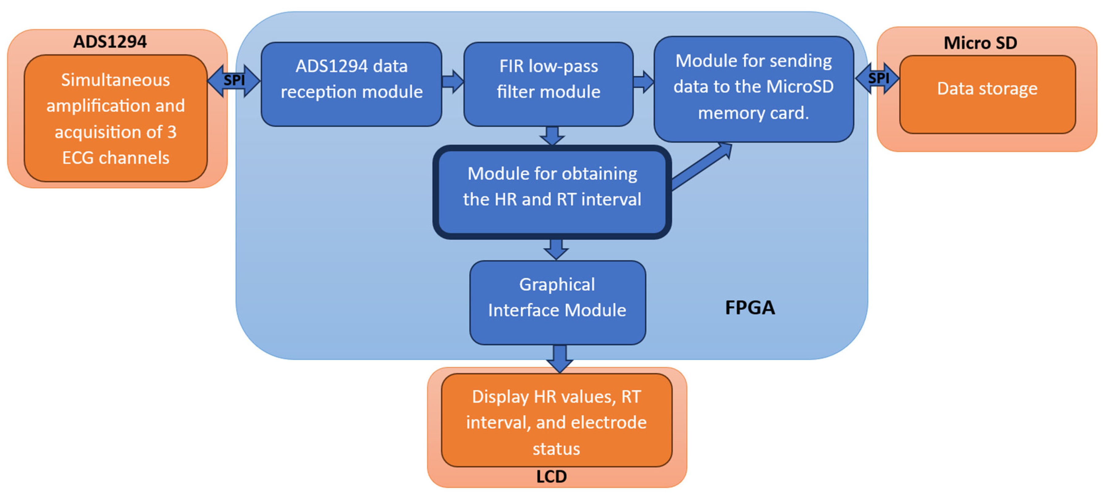
2. Materials and Methods
- Xilinx Cmod A7 development board, which contains a low power consumption Artix-7 XC7A35T-ICPG236C family FPGA.
- Texas Instruments ADS1294 integrated circuit with low power consumption, 4 channels, 24-bit analog-to-digital converters and ECG acquisition module.
- 16 GB Kingston Class 10 micro SDHC memory.
2.1. Software Implemented
2.1.1. Continuous Wavelet Transform
2.1.2. Modules for Obtaining the Wavelet Transform with Splines
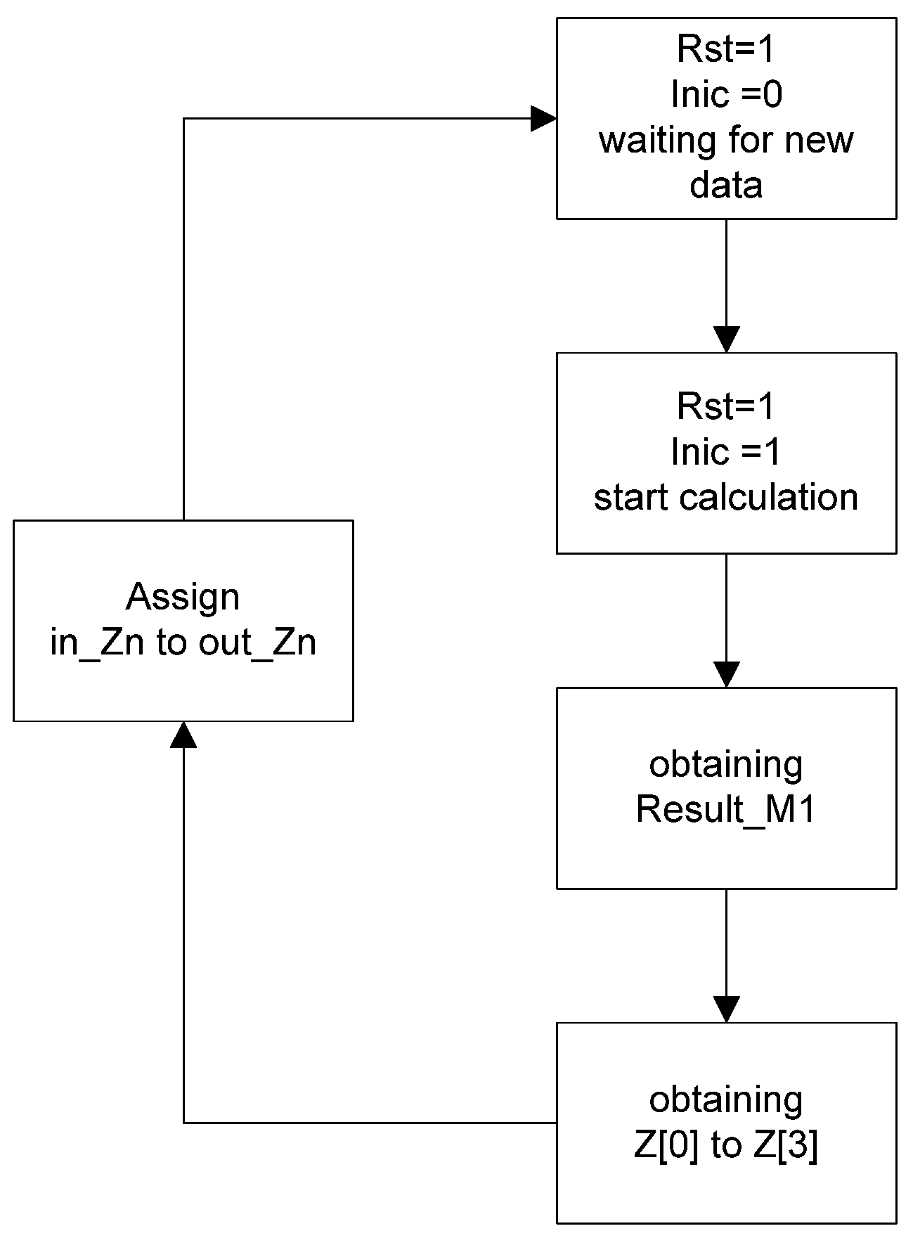
2.1.3. First Submodule
| Pseudocode 1 Submodule 1 |
|
| entity CWT_Submodule_1_Scale_8 is PORT( CLK : in STD_LOGIC; Rst : in STD_LOGIC; Inic : in STD_LOGIC; ADC_input : in STD_LOGIC_VECTOR (23 downto 0); State : out STD_LOGIC_VECTOR (1 downto 0); Result_M1 : out STD_LOGIC_VECTOR (23 downto 0) in_Z0,in_Z1,in_Z2,in_Z3 : in std_logic_vector (39 downto 0); out_Z0,out_Z1,out_Z2,out_Z3 : out std_logic_vector (39 downto 0)); end CWT_Module_1_Scale_8; |
- ‘00’: When Rst = 0, it indicates that the module is locked.
- ‘01’: When Rst = 1, it indicates that the module is not locked but waits for Inic = 1 to start reading (Inic should remain 1 until the obtained result is read).
- ‘10’: Indicates that the values are being calculated.
- ‘11’: Indicates that the calculation of values is complete.
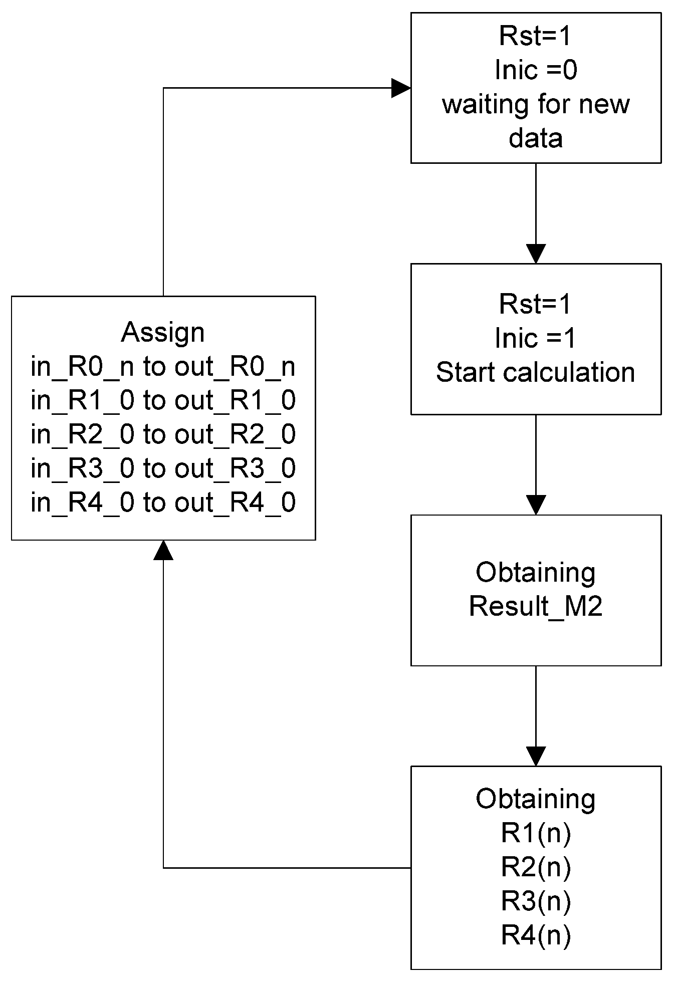
2.1.4. Second Submodule
- k is the position in the input vector.
- is the offset (In this work, it takes a value of 0).
- m is the scale.
| Pseudocode 2 Submodule 2 |
|
| entity CWT_Submodule_2_Scala_8 is PORT( CLK : in STD_LOGIC; Rst : in STD_LOGIC; Inic : in STD_LOGIC; Input_Signal : in STD_LOGIC_VECTOR (23 downto 0); State : out STD_LOGIC_VECTOR (1 downto 0); Result_M2 : out STD_LOGIC_VECTOR (23 downto 0); out_R0_0,…, out_ R0_29 : out STD_LOGIC_VECTOR (30 downto 0); out_R1_0: out STD_LOGIC_VECTOR (30 downto 0); out_R2_0: out STD_LOGIC_VECTOR (30 downto 0); out_R3_0: out STD_LOGIC_VECTOR (30 downto 0); out_R4_0: out STD_LOGIC_VECTOR (30 downto 0); in_R0_0,…, in_R0_29 : in STD_LOGIC_VECTOR (30 downto 0); in_R1_0: in STD_LOGIC_VECTOR (30 downto 0); in_ R2_0: in STD_LOGIC_VECTOR (30 downto 0); in_ R3_0: in STD_LOGIC_VECTOR (30 downto 0); in_ R4_0: in STD_LOGIC_VECTOR (30 downto 0); Resultado_M2 : out STD_LOGIC_VECTOR (23 downto 0)); end CWT_Submodule_2_Scale_8 |
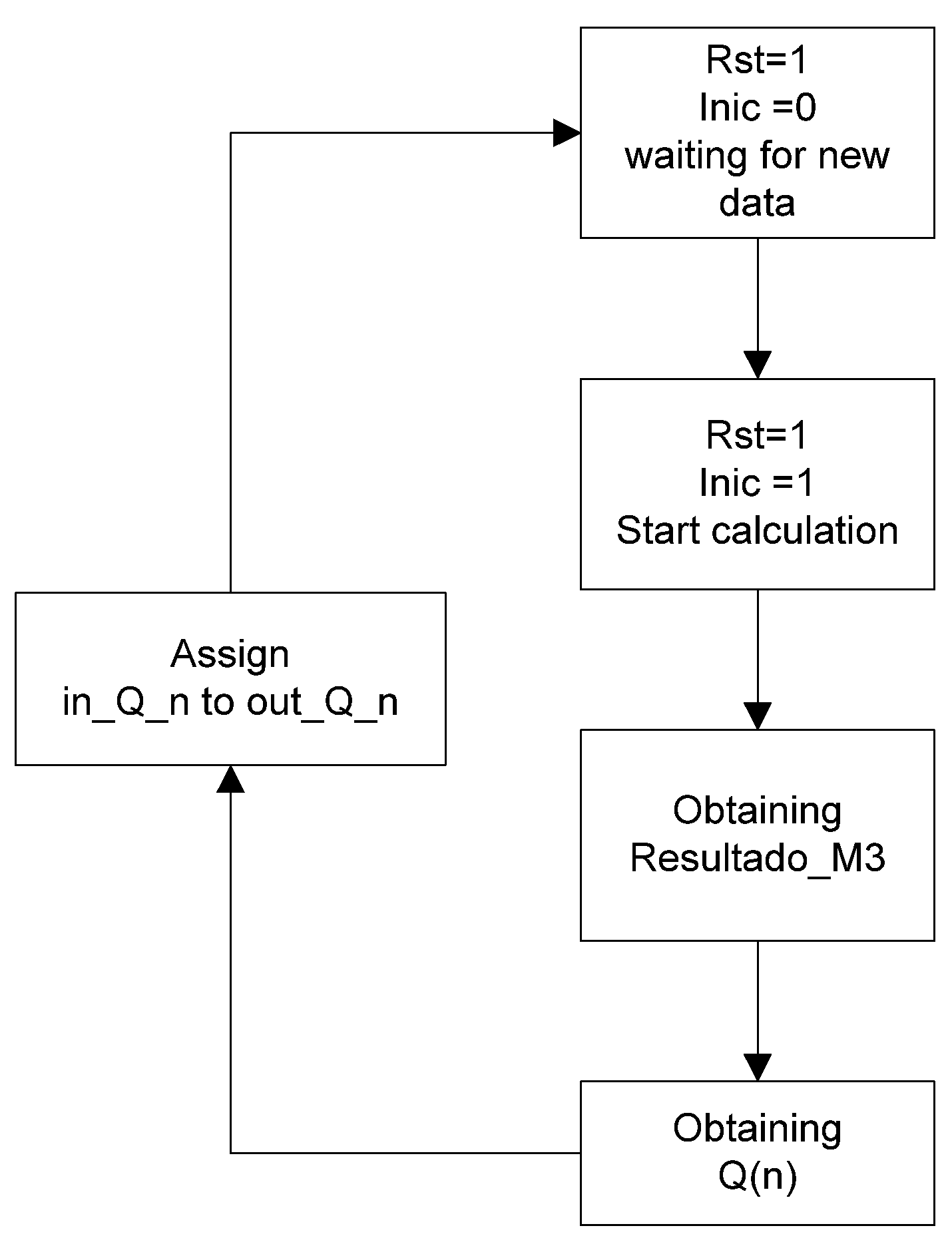
2.1.5. Third Submodule
| Pseudocode 3 Submodule 3 |
| Result_M3= p[0] * Input_Signal + Q[0]; Q[0–6] = Q[1–7]; Q[7] = p[1] * Input_Signal + Q[8]; Q[8–14] = Q[9–15]; Q[15] = p[2] * Input_Signal + Q[16]; Q[16–22] = Q[17–23]; Q[23] = p[3] * Input_Signal + Q[24]; Q[24–30] = z[25–31]; Q[31] = p[4] * Input_Signal + Q[32]; Q[32–38] = Q[33–39]; Q[39] = p[5] * Input_Signal + Q[40]; Q[40–46] = Q[41–47]; Q[47] = p[6] * Input_Signal; |
| entity CWT_Submodule_3_Scale_8 is PORT( CLK : in STD_LOGIC; Rst : in STD_LOGIC; Inic : in STD_LOGIC; Input_Signal : in STD_LOGIC_VECTOR (23 downto 0); Estado : out STD_LOGIC_VECTOR (1 downto 0); Result_M3 : out STD_LOGIC_VECTOR (23 downto 0)); in_Q0,…,in_Q47 : in std_logic_vector (27 downto 0); out_Q0,...,out_Q47: out std_logic_vector (27 downto 0); end CWT_Submodule_3_Scale_8; |
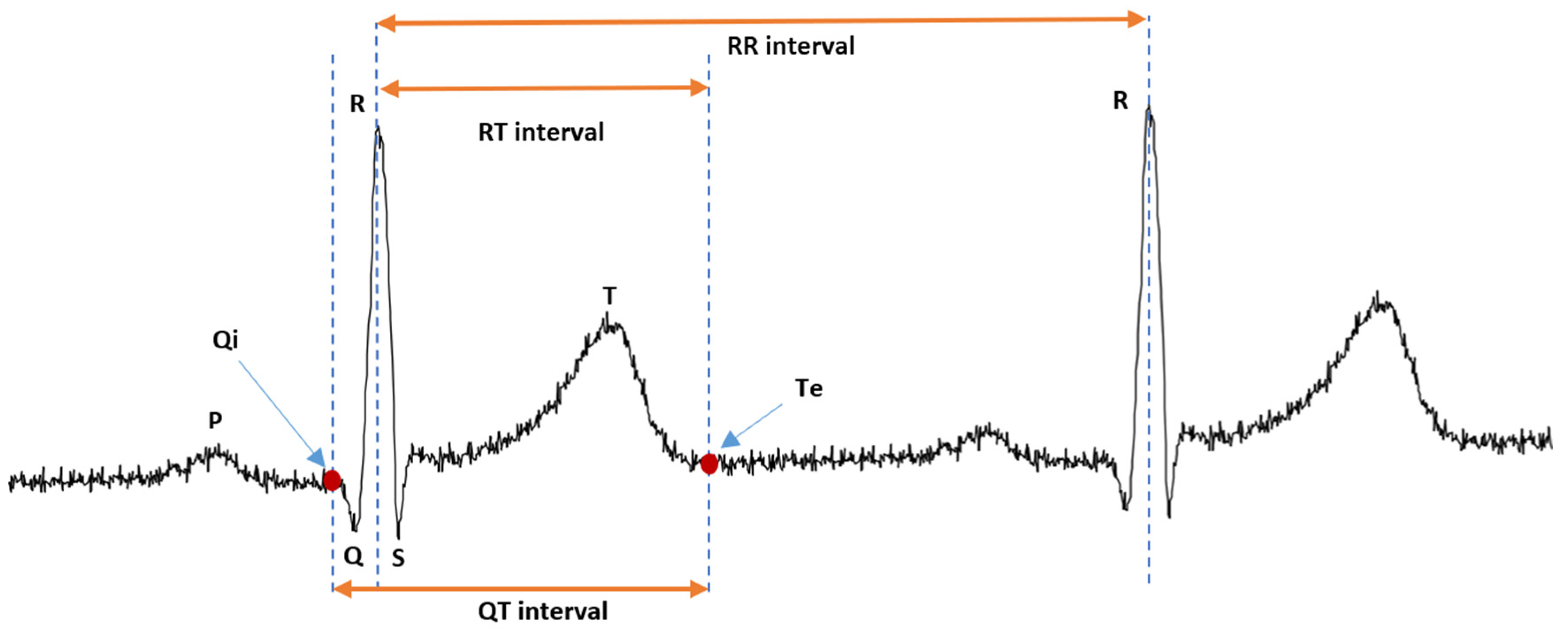
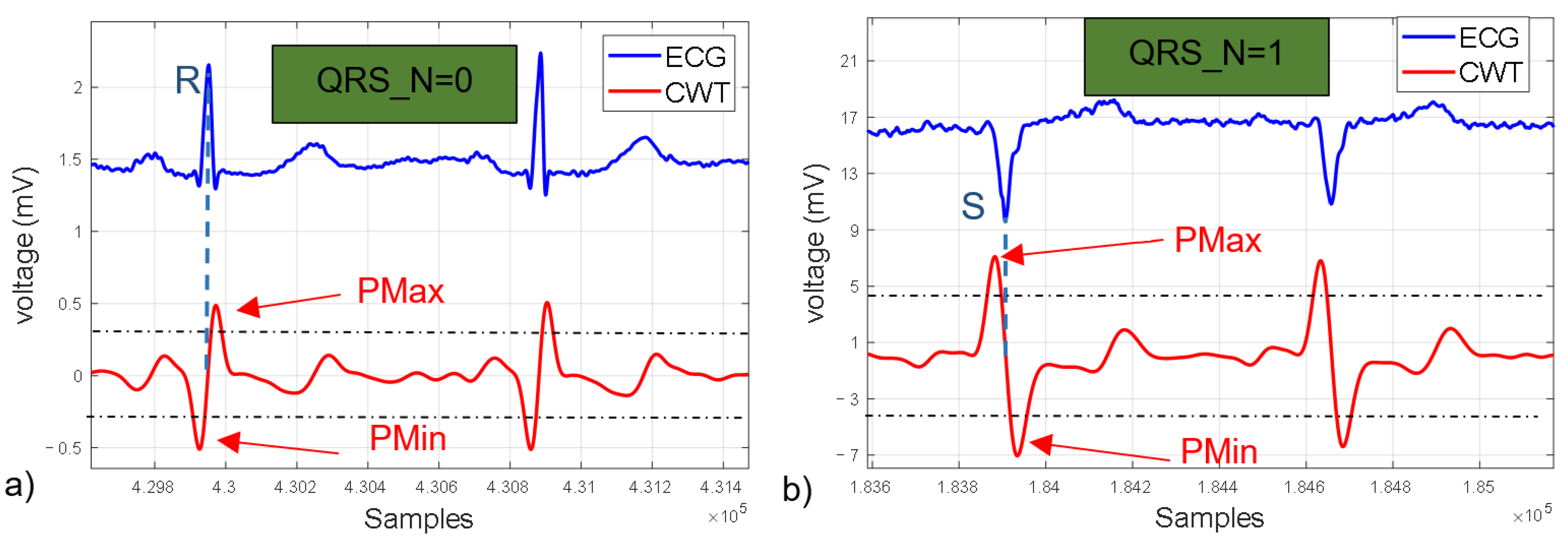
2.1.6. R wave Detection State Machine
- The first function detects if “Signal_input” multiplied by 0.75 is greater than “Output_Memory_Pmax” or less than “Output_Memory_Pmin”, depending on the value of QRS_N, and updates its value.
- The second function is responsible for detecting the zero-crossing of the CWT (peak of the R wave).
- The third function stores the value of the time counter (RR Counter) in the variable “OutputSignalQRS” when the zero-crossing is detected and resets the counter. It should be noted that in this function, the counter is reset for measuring the RT interval.
- The first function detects if the value of Signal_input modules multiplied by 0.75 is greater than “Output_Memory_Pmax” or less than “Output_Memory_Pmin”, depending on the value of QRS_N, and updates its value.
- The second function is responsible for detecting a second zero-crossing.
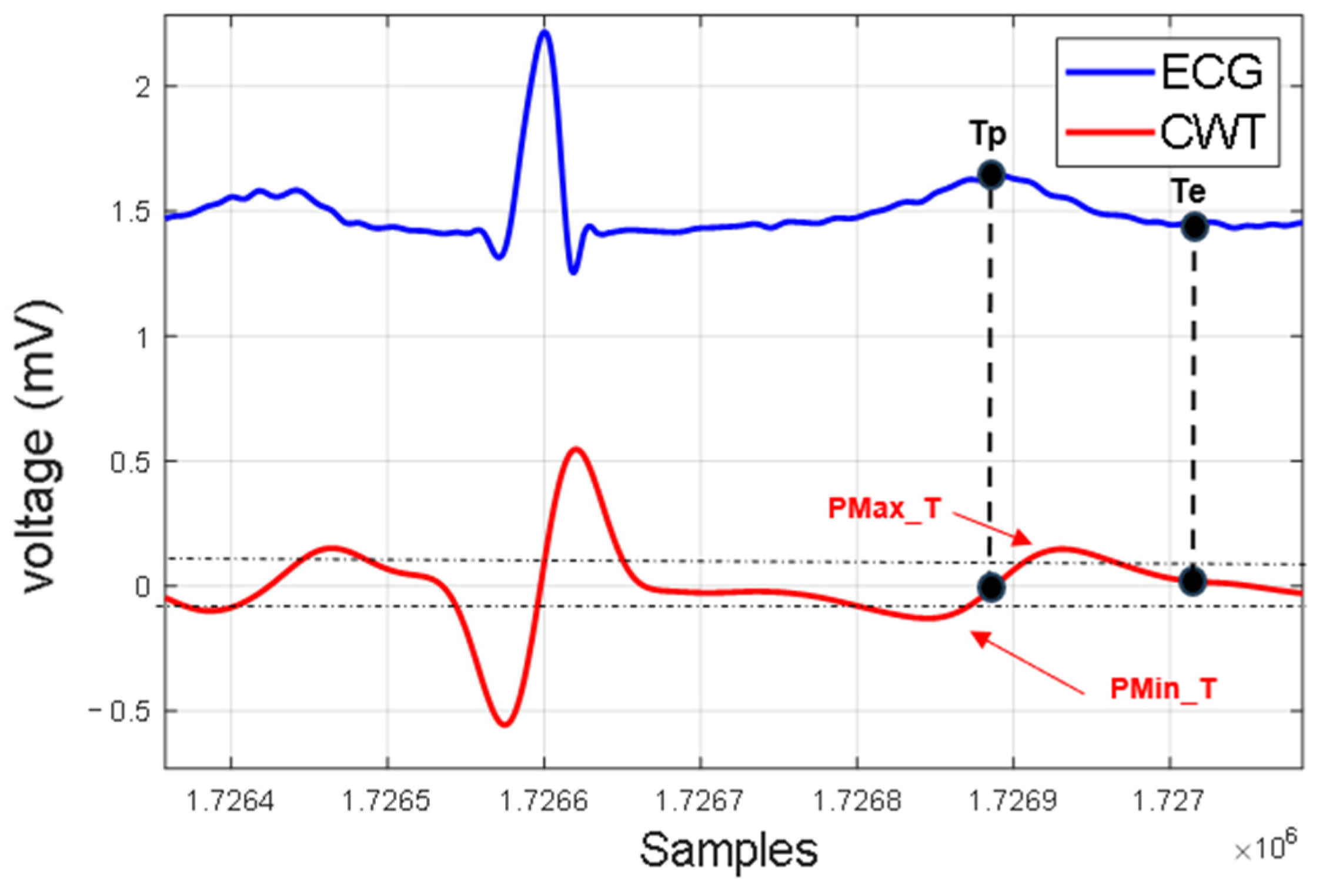
2.1.7. Te Detection State Machine
- The first function defines a search window that depends on the last value of “RR_counter”. If the condition (RR_counter > 700 ms) is met, the search window for the first maximum or minimum of the CWT will be 140 ms. Alternatively, if (RR_Counter < 700 ms), the search window is set to 100 ms.
- The second function is responsible for detecting either the “Pmax_T” or “Pmin_T” point by comparing the value of “Signal_input” with the value stored in the variable “Output_Memory_Pmax_T” or “Output_Memory_Pmin_T”, respectively. If the input signal is greater than the “ Output_Memory_Pmax_T” variable, then the “T_N” signal is set to one; otherwise, it remains at its initial value of zero.
- The first function detects if the value of “Signal_input” multiplied by 0.75 is greater than “Output_Memory_Pmax_T” (for “T_N = 1) or, conversely, if it is less than “Output_Memory _Pmin_T” (for “T_N = 0”). If the condition is met, the corresponding variables are updated.
- The second function detects the first zero-crossing.
- The first function detects if the value of “Signal_input” multiplied by 0.75 is greater than “Output_Memory_Pmin_T” (for “T_N = 1) or, conversely, if it is less than “Output_Memory_Pmax_T” (for “T_N = 0”). If the condition is met, the variables “Output_Memory_Pmax_T” or “Output_Memory_Pmin_T” are updated, respectively.
- The second function detects the second zero-crossing, which corresponds to the point Te.
- The third function copies the value of the time counter “RT_Counter” to the variable “OutputSignalRT” and resets the counter.
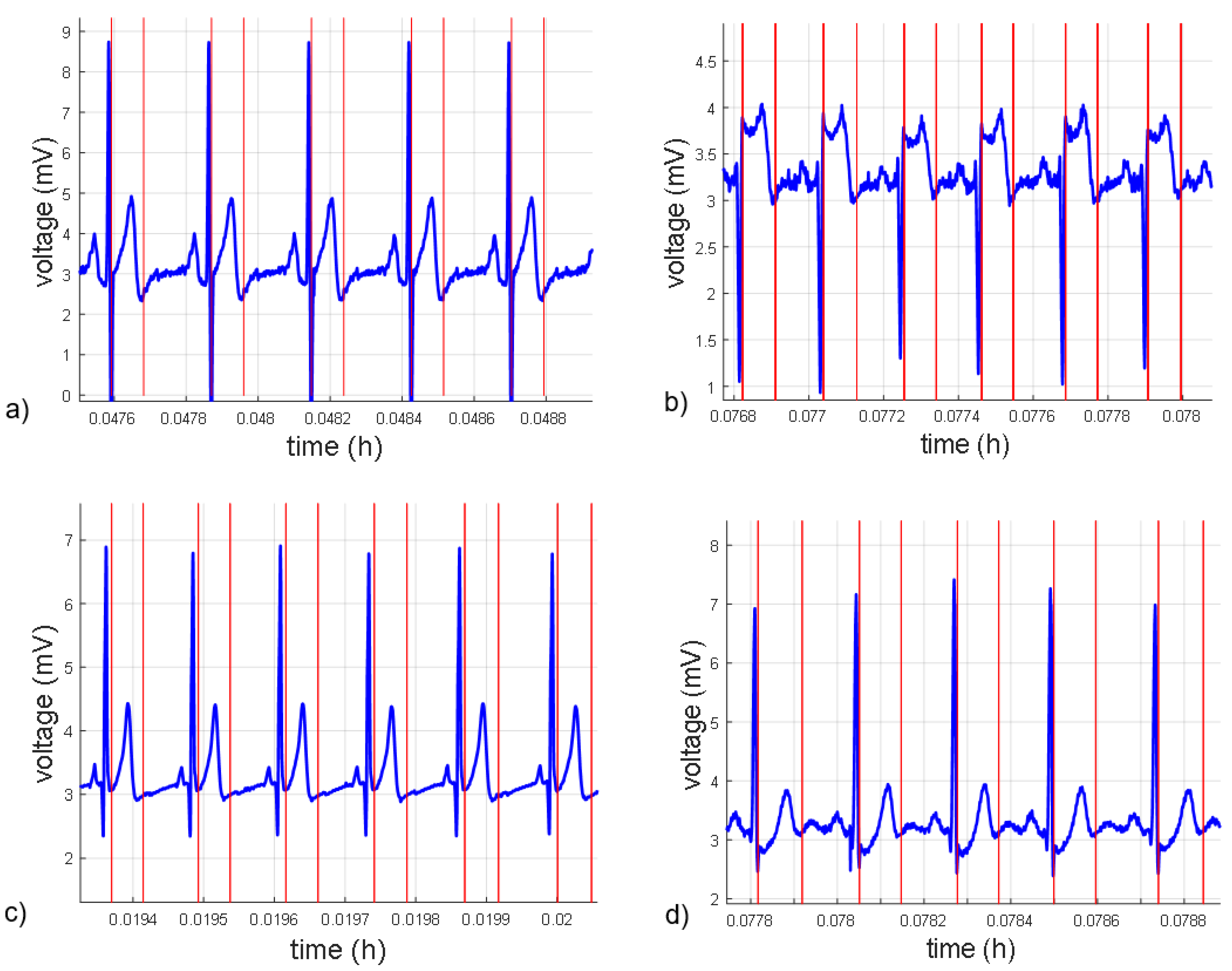
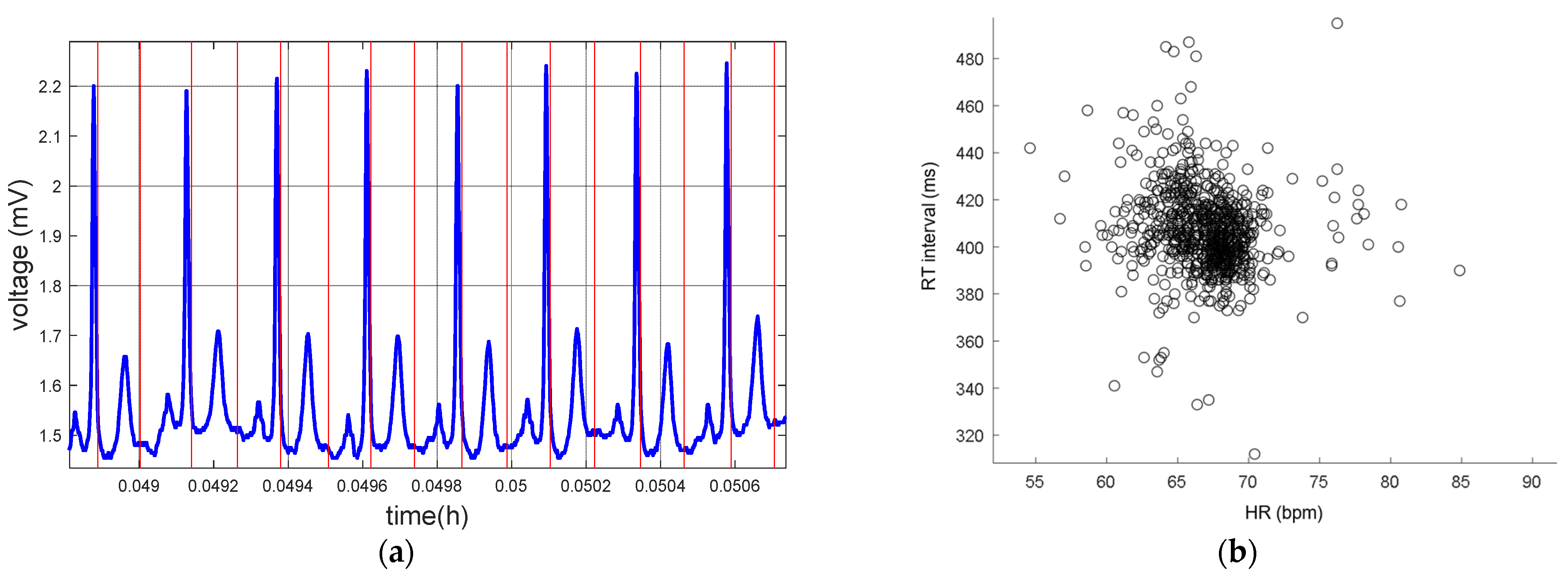
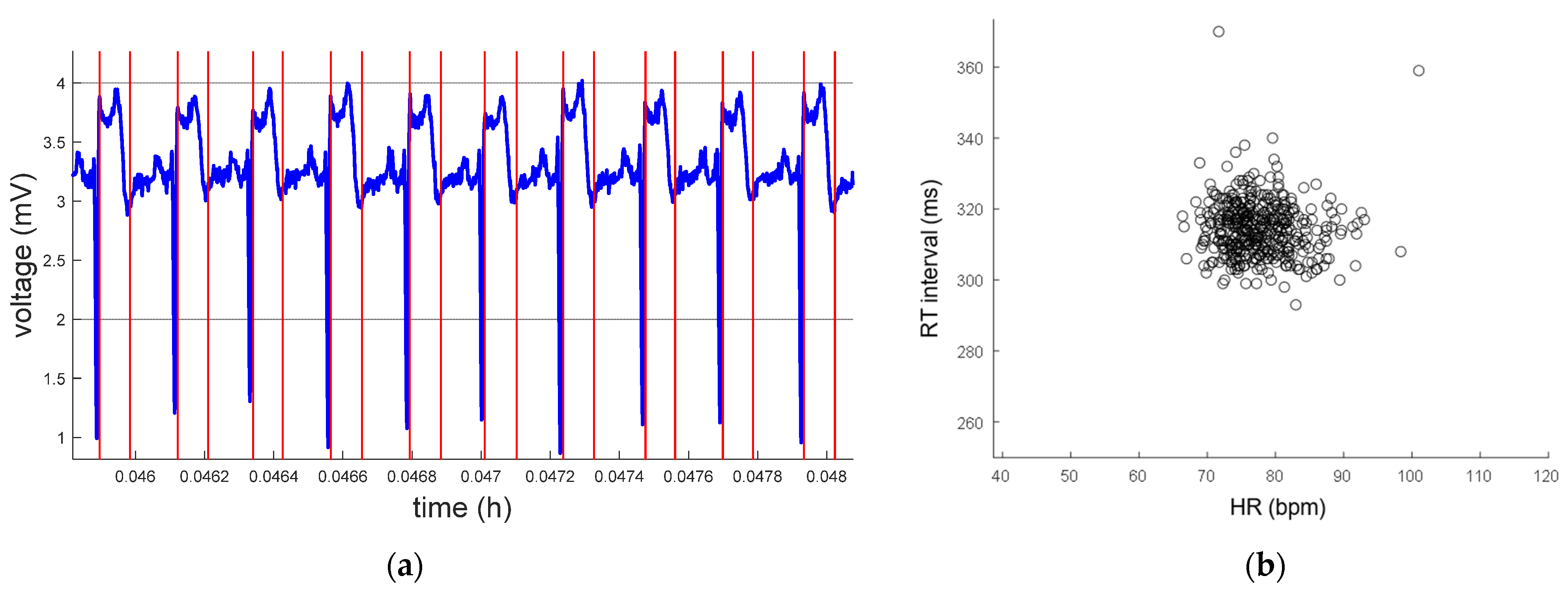
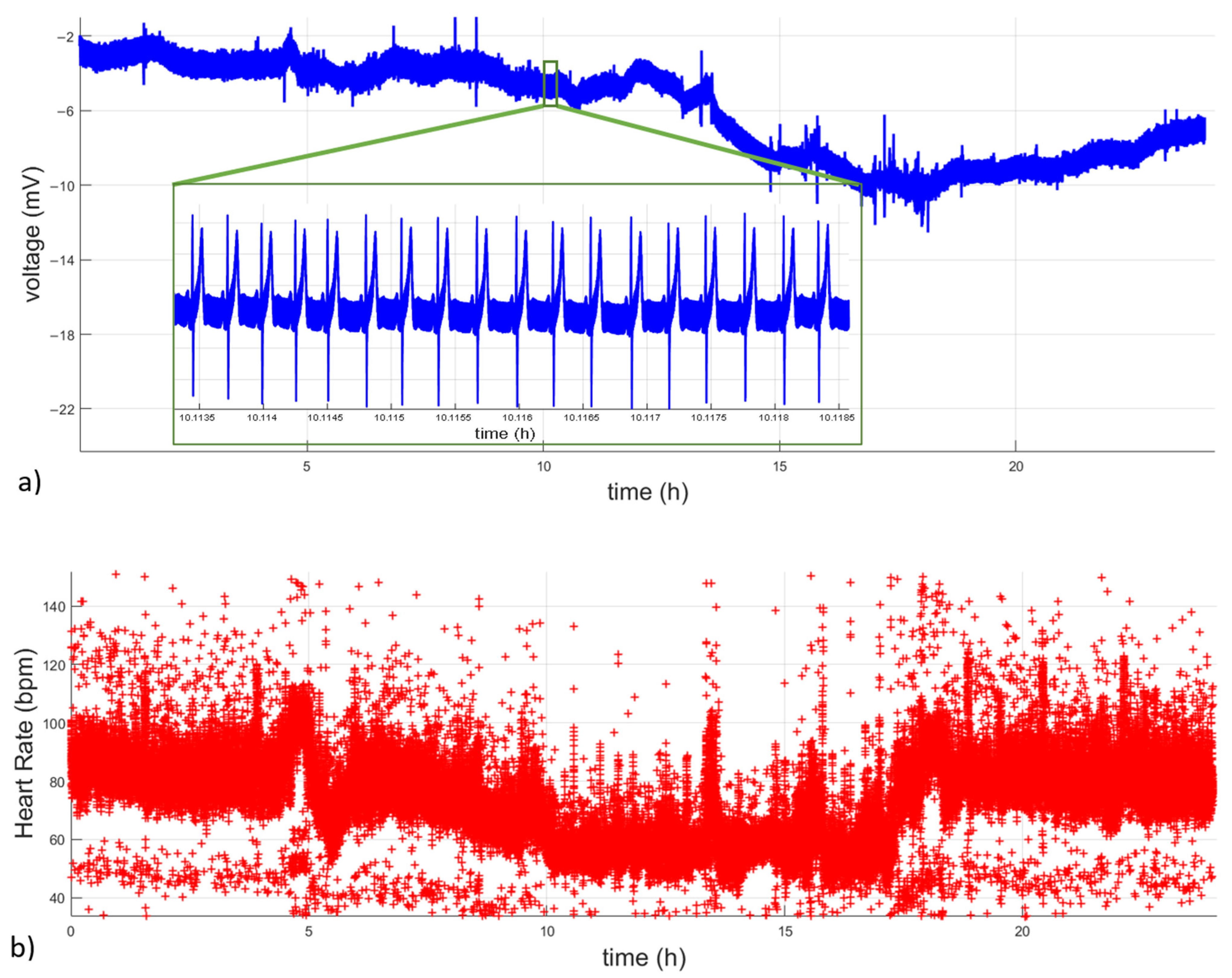
3. Results and Discussion
4. Conclusions
Author Contributions
Funding
Data Availability Statement
Conflicts of Interest
References
- World Health Organization (WHO). Cardiovascular Diseases (CVDs). 11 June 2021. Available online: https://www.who.int/news-room/fact-sheets/detail/cardiovascular-diseases-(cvds) (accessed on 11 July 2023).
- Vaduganathan, M.; Mensah, G.; Turco, J.; Fuster, V.; Roth, G.A. The global burden of cardiovascular diseases and risk. J. Am. Coll. Cardiol. 2022, 80, 2361–2371. [Google Scholar] [CrossRef] [PubMed]
- Cromwell, L.; Weibell, F.J.; Pfeiffer, E.A. Biomedical Instrumentation and Measurements, 2nd ed.; Prentice-Hall: Upper Saddle River, NJ, USA, 1980. [Google Scholar]
- Porta, A.; Girardengo, G.; Bari, V.; George, A.L.; Brink, P.A.; Goosen, A.; Crotti, L.; Schwartz, P.J. Autonomic control of heart rate and QT interval variability influences arrhythmic risk in long QT syndrome type 1. J. Am. Coll. Cardiol. 2015, 65, 367–374. [Google Scholar] [CrossRef] [PubMed]
- Zareba, W.; de Luna, A.B. QT dynamics and variability. Ann. Noninvasive Electrocardiol. 2005, 10, 256–262. [Google Scholar] [CrossRef] [PubMed]
- Task Force of the European Society of Cardiology and the North American Society of Pacing and Electrophysiology. Heart Rate Variability. Circulation 1996, 93, 1043–1065. [Google Scholar] [CrossRef]
- Kennedy, H.L. The history, science, and innovation of Holter technology. Ann. Noninvasive Electrocardiol. 2006, 11, 85–94. [Google Scholar] [CrossRef] [PubMed]
- Zhang, B.; Sieler, L.; Morère, Y.; Bolmont, B.; Bourhis, G. A Modified Algorithm for QRS Complex Detection for FPGA Implementation. Circuits Syst. Signal Process. 2018, 37, 3070–3092. [Google Scholar] [CrossRef]
- Stojanović, R.; Karadaglić, D.; Mirković, M.; Milošević, D. A FPGA system for QRS complex detection based on Integer Wavelet Transform. Meas. Sci. Rev. 2011, 11, 131–138. [Google Scholar] [CrossRef]
- Martínez-Suárez, F.; Alvarado-Serrano, C. Prototype of an Ambulatory ECG Monitoring System with R Wave Detection in Real Time Based on FPGA. In Proceedings of the 2019 16th International Conference on Electrical Engineering, Computing Science and Automatic Control (CCE), Mexico City, Mexico, 11–13 September 2019; pp. 1–5. [Google Scholar] [CrossRef]
- Meddah, K.; Kedir, M.; Bahoura, M.; Zairi, H. FPGA-based system for heart rate monitoring. IET Circuits Devices Syst. 2019, 13, 771–782. [Google Scholar] [CrossRef]
- Giorgio, A.; Guaragnella, C.; Rizzi, M. FPGA-Based Decision Support System for ECG Analysis. J. Low Power Electron. Appl. 2023, 13, 6. [Google Scholar] [CrossRef]
- Panigrahy, D.; Rakshit, M.; Sahu, P.K. FPGA Implementation of Heart Rate Monitoring System. J. Med. Syst. 2016, 40, 49. [Google Scholar] [CrossRef] [PubMed]
- Pavlatos, C.; Dimopoulos, A.; Manis, G.; Papakonstantinou, G. Hardware Implementation of PAN & TOMPKINS QRS Detection Algorithm. In Proceedings of the 3rd European Medical & Biological Engineering Conference—EMBEC05, IFMBE Proceedings, Prague, Czech Republic, 20–25 November 2005. [Google Scholar]
- Meddah, K.; Kedir, T.M.; Zairi, H.; Nouah, M.; Hadji, S.; Ait, M.A.; Bessekri, B.; Cherrih, H. FPGA implementation system for QRS complex detection. Biomed. Eng. Appl. Basis Commun. 2020, 32, 2050005. [Google Scholar] [CrossRef]
- Addison, P.S. Wavelet transforms and the ECG: A review. Physiol. Meas. 2005, 26, R155. [Google Scholar] [CrossRef] [PubMed]
- Li, C.; Zheng, C.; Tai, C. Detection of ECG characteristic points using wavelet transforms. IEEE Trans. Biomed. Eng. 1995, 42, 21–28. [Google Scholar] [CrossRef] [PubMed]
- Martinez, J.P.; Almeida, R.; Olmos, S.; Rocha, A.P.; Laguna, P. A wavelet-based ECG delineator: Evaluation on standard databases. IEEE Trans. Biomed. Eng. 2004, 51, 570–581. [Google Scholar] [CrossRef] [PubMed]
- García-Limón, J.A.; Martínez-Suárez, F.; Alvarado-Serrano, C. Prototype of an Ambulatory Long-Term ECG Monitoring System for Real Time Detection of QRS Complex and T Wave End Based on FPGA. In Proceedings of the 2021 18th International Conference on Electrical Engineering, Computing Science and Automatic Control (CCE), Mexico City, Mexico, 10–12 November 2021; pp. 1–6. [Google Scholar] [CrossRef]
- Mallat, S.G. A theory for multiresolution signal decomposition: The wavelet representation. IEEE Trans. Pattern Anal. Mach. Intell. 1989, 11, 674–693. [Google Scholar] [CrossRef]
- Unser, M.; Aldroubi, A.; Schiff, S.J. Fast implementation of the continuous wavelet transform with integer scales. IEEE Trans. Signal Process. 1994, 42, 3519–3523. [Google Scholar] [CrossRef] [PubMed]
- Alvarado, C.; Arregui, J.; Ramos, J.; Pallàs-Areny, R. Automatic detection of ECG ventricular activity waves using continuous spline wavelet transform. In Proceedings of the 2nd International Conference on Electrical and Electronics Engineering, ICEEE and XI Conference on Electrical Engineering, CIE 2005, Mexico City, Mexico, 7–9 September 2005; pp. 189–192. [Google Scholar] [CrossRef]
- Martínez-Suárez, F.; Alvarado-Serrano, C. VHDL Module for the R Wave Detection in Real Time Using Continuous Wavelet Transform. In Proceedings of the 2019 16th International Conference on Electrical Engineering, Computing Science and Automatic Control (CCE), Mexico City, Mexico, 11–13 September 2019; pp. 1–5. [Google Scholar] [CrossRef]
- Laguna, P.; Mark, R.G.; Goldberg, A.; Moody, G.B. A database for evaluation of algorithms for measurement of QT and other waveform intervals in the ECG. In Proceedings of the Computers in Cardiology 1997, Lund, Sweden, 7–10 September 1997; pp. 673–676. [Google Scholar] [CrossRef]
- CSE Working Party. Recommendations for measurement standards in quantitative electrocardiography. The CSE Working Party. Eur. Heart J. 1985, 6, 815–825. [Google Scholar] [CrossRef]
- Moody, G.B. The PhysioNet/Computers in Cardiology Challenge 2008: T-Wave Alternans. Comput. Cardiol. 2008, 35, 505–508. [Google Scholar]
- Goldberger, A.; Amaral, L.; Glass, L.; Hausdorff, J.; Ivanov, P.C.; Mark, R.; Mietus, J.E.; Moody, G.B.; Peng, C.K.; Stanley, H.E. PhysioBank, PhysioToolkit, and PhysioNet: Components of a new research resource for complex physiologic signals. Circulation 2000, 101, e215–e220. [Google Scholar] [CrossRef]


| Original Coefficients | Coefficients Multiplied by 216 | |
|---|---|---|
| b0 | 1/120 = 0.0083 | 543 |
| b1 | 1/26 = 0.2167 | 14,201 |
| b2 | 1/66 = 0.5500 | 36,044 |
| b3 | 1/26 = 0.2167 | 14,201 |
| b4 | 1/120 = 0.0083 | 543 |
Disclaimer/Publisher’s Note: The statements, opinions and data contained in all publications are solely those of the individual author(s) and contributor(s) and not of MDPI and/or the editor(s). MDPI and/or the editor(s) disclaim responsibility for any injury to people or property resulting from any ideas, methods, instructions or products referred to in the content. |
© 2023 by the authors. Licensee MDPI, Basel, Switzerland. This article is an open access article distributed under the terms and conditions of the Creative Commons Attribution (CC BY) license (https://creativecommons.org/licenses/by/4.0/).
Share and Cite
García Limón, J.A.; Martínez-Suárez, F.; Alvarado-Serrano, C. Implementation of Wavelet-Transform-Based Algorithms in an FPGA for Heart Rate and RT Interval Automatic Measurements in Real Time: Application in a Long-Term Ambulatory Electrocardiogram Monitor. Micromachines 2023, 14, 1748. https://doi.org/10.3390/mi14091748
García Limón JA, Martínez-Suárez F, Alvarado-Serrano C. Implementation of Wavelet-Transform-Based Algorithms in an FPGA for Heart Rate and RT Interval Automatic Measurements in Real Time: Application in a Long-Term Ambulatory Electrocardiogram Monitor. Micromachines. 2023; 14(9):1748. https://doi.org/10.3390/mi14091748
Chicago/Turabian StyleGarcía Limón, José Alberto, Frank Martínez-Suárez, and Carlos Alvarado-Serrano. 2023. "Implementation of Wavelet-Transform-Based Algorithms in an FPGA for Heart Rate and RT Interval Automatic Measurements in Real Time: Application in a Long-Term Ambulatory Electrocardiogram Monitor" Micromachines 14, no. 9: 1748. https://doi.org/10.3390/mi14091748
APA StyleGarcía Limón, J. A., Martínez-Suárez, F., & Alvarado-Serrano, C. (2023). Implementation of Wavelet-Transform-Based Algorithms in an FPGA for Heart Rate and RT Interval Automatic Measurements in Real Time: Application in a Long-Term Ambulatory Electrocardiogram Monitor. Micromachines, 14(9), 1748. https://doi.org/10.3390/mi14091748