


Phase Behavior and Role of Organic Additives for Self-Doped CsPbI3 Perovskite Semiconductor Thin Films


 , ,
, , 
Abstract
1. Introduction
2. Materials and Methods
2.1. Materials
2.2. Methods
2.3. Characterization
2.4. Computational Methods
3. Results and Discussion
4. Conclusions
Supplementary Materials
Author Contributions
Funding
Data Availability Statement
Acknowledgments
Conflicts of Interest
References
- Gidey, A.T.; Kim, J.Y. Tuning the crystallization process of perovskite active layer using a functionalized graphene oxide for enhanced photovoltaic performance. J. Mater. Sci. Mater. Electron. 2020, 31, 12257–12268. [Google Scholar] [CrossRef]
- Gidey, A.T.; Assayehegn, E.; Kim, J.Y. Hydrophilic Surface-Driven Crystalline Grain Growth of Perovskites on Metal Oxides. ACS Appl. Energy Mater. 2021, 4, 6923–6932. [Google Scholar] [CrossRef]
- Ma̧czka, M.; Ptak, M.; Ga̧gor, A.; Stefańska, D.; Zarȩba, J.K.; Sieradzki, A. Methylhydrazinium Lead Bromide: Noncentrosymmetric Three-Dimensional Perovskite with Exceptionally Large Framework Distortion and Green Photoluminescence. Chem. Mater. 2020, 32, 1667–1673. [Google Scholar] [CrossRef]
- Stefańska, D.; Ptak, M.; Ma̧czka, M. Synthesis, Photoluminescence and Vibrational Properties of Aziridinium Lead Halide Perovskites. Molecules 2022, 27, 7949. [Google Scholar] [CrossRef] [PubMed]
- Sun, J.; Wu, J.; Tong, X.; Lin, F.; Wang, Y.; Wang, Z.M. Organic/Inorganic Metal Halide Perovskite Optoelectronic Devices beyond Solar Cells. Adv. Sci. 2018, 5, 1700780. [Google Scholar] [CrossRef]
- Yang, H.; Wang, H.; Wang, K.; Liu, D.; Zhao, L.; Chen, D.; Zhu, W.; Zhang, J.; Zhang, C. Recent Progress of Film Fabrication Process for Carbon-Based All-Inorganic Perovskite Solar Cells. Crystals 2023, 13, 679. [Google Scholar] [CrossRef]
- Moot, T.; Marshall, A.R.; Wheeler, L.M.; Habisreutinger, S.N.; Tracy, H.; Boyd, C.C.; Dikova, D.R.; Pach, G.F.; Hazarika, A.; Mcgehee, D.; et al. CsI-Antisolvent Adduct Formation in All-Inorganic Metal Halide Perovskites. Adv. Energy Mater. 2020, 10, 1903365. [Google Scholar] [CrossRef]
- Murugadoss, G.; Thangamuthu, R.; Senthil Kumar, S.M.; Anandhan, N.; Rajesh Kumar, M.; Rathishkumar, A. Synthesis of Ligand-Free, Large Scale with High Quality All-Inorganic CsPbI3 and CsPb2Br5 Nanocrystals and Fabrication of All-Inorganic Perovskite Solar Cells. J. Alloys Compd. 2019, 787, 17–26. [Google Scholar] [CrossRef]
- Kulbak, M.; Gupta, S.; Kedem, N.; Levine, I.; Bendikov, T.; Hodes, G.; Cahen, D. Cesium Enhances Long-Term Stability of Lead Bromide Perovskite-Based Solar Cells. J. Phys. Chem. Lett. 2016, 7, 167–172. [Google Scholar] [CrossRef] [PubMed]
- Stoumpos, C.C.; Malliakas, C.D.; Kanatzidis, M.G. Semiconducting Tin and Lead Iodide Perovskites with Organic Cations: Phase Transitions, High Mobilities, and Near-Infrared Photoluminescent Properties. Inorg. Chem. 2013, 52, 9019–9038. [Google Scholar] [CrossRef]
- Eperon, G.E.; Stranks, S.D.; Menelaou, C.; Johnston, M.B.; Herz, L.M.; Snaith, H.J. Formamidinium lead trihalide: A broadly tunable perovskite for efficient planar heterojunction solar cells. Energy Environ. Sci. 2014, 7, 982–988. [Google Scholar] [CrossRef]
- Zeng, L.; Chen, S.; Forberich, K.; Brabec, C.J.; Mai, Y.; Guo, F. Controlling the Crystallization Dynamics of Photovoltaic Perovskite Layers on Larger-Area Coatings. Energy Environ. Sci. 2020, 13, 4666–4690. [Google Scholar] [CrossRef]
- Ding, N.; Wu, Y.; Xu, W.; Lyu, J.; Wang, Y.; Zi, L.; Shao, L.; Sun, R.; Wang, N.; Liu, S. A novel approach for designing efficient broadband photodetectors expanding from deep ultraviolet to near infrared. Light Sci. Appl. 2022, 11, 91. [Google Scholar] [CrossRef] [PubMed]
- Cao, L.; Liu, X.; Li, Y.; Li, X.; Du, L.; Chen, S.; Zhao, S.; Wang, C. Recent Progress in All-Inorganic Metal Halide Nanostructured Perovskites: Materials Design, Optical Properties, and Application. Front. Phys. 2021, 16, 33201. [Google Scholar] [CrossRef]
- Cheng, J.; Fan, Z.; Dong, J. Research Progress of Green Solvent in CsPbBr3 Perovskite Solar Cells. Nanomaterials 2023, 13, 991. [Google Scholar] [CrossRef]
- Zeng, Q.; Zhang, X.; Liu, C.; Feng, T.; Chen, Z.; Zhang, W.; Zheng, W.; Zhang, H.; Yang, B. Inorganic CsPbI2Br Perovskite Solar Cells: The Progress and Perspective. Sol. RRL 2019, 3, 1800239. [Google Scholar] [CrossRef]
- Dong, Y.; Zhao, Y.; Zhang, S.; Dai, Y.; Liu, L.; Li, Y.; Chen, Q. Recent Advances toward Practical Use of Halide Perovskite Nanocrystals. J. Mater. Chem. A 2018, 6, 21729–21746. [Google Scholar] [CrossRef]
- Faridi, A.W.; Imran, M.; Tariq, G.H.; Ullah, S.; Noor, S.F.; Ansar, S.; Sher, F. Synthesis and Characterization of High-Efficiency Halide Perovskite Nanomaterials for Light-Absorbing Applications. Ind. Eng. Chem. Res. 2023, 62, 4494–4502. [Google Scholar] [CrossRef]
- Hasan, M.S.; Alom, J.; Asaduzzaman, M.; Ahmed, M.B.; Hossain, M.D.; Saem, A.; Masud, J.; Thakare, J.; Hossain, M.A. Recent Criterion on Stability Enhancement of Perovskite Solar Cells. Processes 2022, 10, 1408. [Google Scholar] [CrossRef]
- Ma, J.; Su, J.; Lin, Z.; He, J.; Zhou, L.; Li, T.; Zhang, J.; Liu, S.; Chang, J.; Hao, Y. Double Side Interfacial Optimization for Low-Temperature Stable CsPbI2Br Perovskite Solar Cells with High Efficiency Beyond 16%. Energy Environ. Mater. 2022, 5, 637–644. [Google Scholar] [CrossRef]
- Kirakosyan, A.; Kim, Y.; Sihn, R.; Jeon, M.; Jeong, J. Solubility-Controlled Room-Temperature Synthesis of Cesium Lead Halide Perovskite Nanocrystals. ChemNanoMat 2020, 6, 1863–1869. [Google Scholar] [CrossRef]
- Dong, Y.; Qiao, T.; Kim, D.; Parobek, D.; Rossi, D.; Son, D.H. Precise Control of Quantum Confinement in Cesium Lead Halide Perovskite Quantum Dots via Thermodynamic Equilibrium. Nano Lett. 2018, 18, 3716–3722. [Google Scholar] [CrossRef] [PubMed]
- Bioki, H.A.; Moshaii, A.; Zarandi, M.B. Improved Morphology, Structure and Optical Properties of CH3NH3PbI3 Film via HQ Additive in PbI2 Precursor Solution for Efficient and Stable Mesoporous Perovskite Solar Cells. Synth. Met. 2022, 283, 116965. [Google Scholar] [CrossRef]
- Kumar, A.; Rana, N.K.; Rani, S.; Ghosh, D.S. Toward all-Inorganic Perovskite Solar Cells: Materials, performance, and stability. Int. J. Energy Res. 2022, 46, 14659–14695. [Google Scholar] [CrossRef]
- Wang, J.; Che, Y.; Duan, Y.; Liu, Z.; Yang, S.; Xu, D.; Fang, Z.; Lei, X.; Li, Y.; Liu, S. 21.15%-Efficiency and Stable γ -CsPbI3 Perovskite Solar Cells Enabled by an Acyloin Ligand. Adv. Mater. 2023, 35, 2210223. [Google Scholar] [CrossRef]
- Park, J.; Kim, J.; Yun, H.-S.; Paik, M.J.; Noh, E.; Mun, H.J.; Kim, M.G.; Shin, T.J.; Seok, S.I. Controlled growth of perovskite layers with volatile alkylammonium chlorides. Nature 2023, 616, 724–730. [Google Scholar] [CrossRef]
- Zhu, X.; Ge, L.; Wang, Y.; Li, M.; Zhang, R.; Xu, M.; Zhao, Z.; Lv, W.; Chen, R. Recent Advances in Enhancing and Enriching the Optical Properties of Cl-Based CsPbX3 Nanocrystals. Adv. Optical Mater. 2021, 9, 2100058. [Google Scholar] [CrossRef]
- Xiang, W.; Liu, S.F.; Tress, W. A review on the stability of inorganic metal halide perovskites: Challenges and opportunities for stable solar cells. Energy Environ. Sci. 2021, 14, 2090–2113. [Google Scholar] [CrossRef]
- Zhao, Y.; Zhu, K. Organic–inorganic hybrid lead halide perovskites for optoelectronic and electronic applications. Chem. Soc. Rev. 2016, 45, 655–689. [Google Scholar] [CrossRef]
- Alaei, A.; Circelli, A.; Yuan, Y.; Yang, Y.; Lee, S.S. Polymorphism in metal halide perovskites. Mater. Adv. 2021, 2, 47–63. [Google Scholar] [CrossRef]
- Wang, B.; Novendra, N.; Navrotsky, A. Energetics, Structures, and Phase Transitions of Cubic and Orthorhombic Cesium Lead Iodide (CsPbI3) Polymorphs. J. Am. Chem. Soc. 2019, 141, 14501–14504. [Google Scholar] [CrossRef] [PubMed]
- Sutton, R.J.; Filip, M.R.; Haghighirad, A.A.; Sakai, N.; Wenger, B.; Giustino, F.; Snaith, H.J. Cubic or Orthorhombic? Revealing the Crystal Structure of Metastable Black-Phase CsPbI3 by Theory and Experiment. ACS Energy Lett. 2018, 3, 1787–1794. [Google Scholar] [CrossRef]
- Xu, F.; Li, Y.; Liu, N.; Han, Y.; Zou, M.; Song, T. 1D Perovskitoid as Absorbing Material for Stable Solar Cells. Crystals 2021, 11, 241. [Google Scholar] [CrossRef]
- Xu, F.; Zhang, M.; Li, Z.; Yang, X.; Zhu, R. Challenges and Perspectives toward Future Wide-Bandgap Mixed-Halide Perovskite Photovoltaics. Adv. Energy Mater. 2023, 13, 2203911. [Google Scholar] [CrossRef]
- Tan, S.; Yu, B.; Cui, Y.; Meng, F.; Huang, C.; Li, Y.; Chen, Z.; Wu, H.; Shi, J.; Luo, Y.; et al. Temperature-Reliable Low-Dimensional Perovskites Passivated Black-Phase CsPbI3 toward Stable and Efficient Photovoltaics. Angew. Chem. Int. Ed. 2022, 61, e202201300. [Google Scholar] [CrossRef]
- Bian, H.; Wang, Q.; Yang, S.; Yan, C.; Wang, H.; Liang, L.; Jin, Z.; Wang, G.; Liu, S. Nitrogen-Doped Graphene Quantum Dots for 80% Photoluminescence Quantum Yield for Inorganic γ-CsPbI3 Perovskite Solar Cells with Efficiency beyond 16%. J. Mater. Chem. A 2019, 7, 5740–5747. [Google Scholar] [CrossRef]
- Ahmad, M.; Rehman, G.; Ali, L.; Shafiq, M.; Iqbal, R.; Ahmad, R.; Khan, T.; Jalali-Asadabadi, S.; Maqbool, M.; Ahmad, I. Structural, Electronic and Optical Properties of CsPbX3(X = Cl, Br, I) for Energy Storage and Hybrid Solar Cell Applications. J. Alloys Compd. 2017, 705, 828–839. [Google Scholar] [CrossRef]
- Zhang, F.; Zhu, K. Additive Engineering for Efficient and Stable Perovskite Solar Cells. Adv. Energy Mater. 2020, 10, 1902579. [Google Scholar] [CrossRef]
- Zhang, L.; Han, B.; Liu, Z.; Yao, Y.; Xu, L.; Wang, P.; Lin, P.; Wu, X.; Yu, X.; Cui, C. Additive Engineering on Spiro-OMeTAD Hole Transport Material for CsPbI3 All-Inorganic Perovskite Solar Cells with Improved Performance and Stability. J. Alloys Compd. 2022, 911, 164972. [Google Scholar] [CrossRef]
- Khorshidi, E.; Rezaei, B.; Kavousighahfarokhi, A.; Hanisch, J.; Reus, M.A.; Mu, P.; Ameri, T. Antisolvent Additive Engineering for Boosting Performance and Stability of Graded Heterojunction Perovskite Solar Cells Using Amide-Functionalized Graphene Quantum Dots. ACS Appl. Mater. Interfaces 2022, 14, 54623–54634. [Google Scholar] [CrossRef]
- Zhou, Y.; Chen, J.; Bakr, O.M.; Sun, H.T. Metal-Doped Lead Halide Perovskites: Synthesis, Properties, and Optoelectronic Applications. Chem. Mater. 2018, 30, 6589–6613. [Google Scholar] [CrossRef]
- Tian, J.; Wang, J.; Xue, Q.; Niu, T.; Yan, L.; Zhu, Z.; Li, N.; Brabec, C.J.; Yip, H.-L.; Cao, Y. Composition Engineering of All-Inorganic Perovskite Film for Efficient and Operationally Stable Solar Cells. Adv. Funct. Mater. 2020, 30, 2001764. [Google Scholar] [CrossRef]
- Sun, H.; Zhang, J.; Gan, X.; Yu, L.; Yuan, H.; Shang, M.; Lu, C.; Hou, D.; Hu, Z.; Zhu, Y.; et al. Pb-Reduced CsPb0.9Zn0.1I2Br Thin Films for Efficient Perovskite Solar Cells. Adv. Energy Mater. 2019, 9, 1900896. [Google Scholar] [CrossRef]
- Liu, B.; Long, M.; Cai, M.-Q.; Yang, J. Interface engineering of CsPbI3-black phosphorus van der Waals heterostructure. Appl. Phys. Lett. 2018, 112, 043901. [Google Scholar] [CrossRef]
- Eperon, G.E.; Paternò, G.M.; Sutton, R.J.; Zampetti, A.; Haghighirad, A.A.; Cacialli, F.; Snaith, H.J. Inorganic caesium lead iodide perovskite solar cells. J. Mater. Chem. A 2015, 3, 19688–19695. [Google Scholar] [CrossRef]
- Marronnier, A.; Roma, G.; Boyer-richard, S.; Pedesseau, L.; Jancu, J.; Bonnassieux, Y.; Katan, C.; Stoumpos, C.C.; Kanatzidis, M.G.; Even, J. Anharmonicity and Disorder in the Black Phases of Cesium Lead Iodide Used for Stable Inorganic Perovskite Solar Cells. ACS Nano 2018, 12, 3477–3486. [Google Scholar] [CrossRef]
- Zhang, Q.; Zhou, Y.; Wei, Y.; Tai, M.; Gu, Y.; Han, J.; Yin, X.; Li, J.; Lin, H. Improved phase stability of γ-CsPbI3 perovskite nanocrystals using the interface effect using iodine modified graphene oxide. J. Mater. Chem. C 2020, 8, 2569–2578. [Google Scholar] [CrossRef]
- Wang, K.; Jin, Z.; Liang, L.; Bian, H.; Wang, H.; Feng, J.; Wang, Q.; Liu, S. Chlorine doping for black γ-CsPbI3 solar cells with stabilized efficiency beyond 16%. Nano Energy 2019, 58, 175–182. [Google Scholar] [CrossRef]
- Huang, L.; Xu, P.; Yu, F.; Liu, J.; Shirai, Y.; Zhang, X.-P.; Li, C.-H.; Song, Y. A stabilized γ-CsPbI3 by poly(allylamine hydrochloride) for wide-band gap perovskites solar cells with enhanced performance. J. Solid State Chem. 2023, 324, 124087. [Google Scholar] [CrossRef]
- Zhang, Z.; Ji, R.; Kroll, M.; Hofstetter, Y.J.; Jia, X.; Becker-Koch, D.; Paulus, F.; Löffler, M.; Nehm, F.; Leo, K.; et al. Efficient Thermally Evaporated γ-CsPbI3 Perovskite Solar Cells. Adv. Energy Mater. 2021, 11, 2100299. [Google Scholar] [CrossRef]
- Qiu, Z.; Wang, F.; Wang, C.; Zhu, C.; Wang, H.; Chen, Q.; Chen, Y.; Zhang, Y.; Guo, Z.; Li, N.; et al. Phase Transformation Barrier Modulation of CsPbI3 Films via PbI3− Complex for Efficient All-Inorganic Perovskite Photovoltaics. Nano Energy 2022, 99, 107338. [Google Scholar] [CrossRef]
- Pereyra, C.; Xie, H.; Lira-Cantu, M. Additive engineering for stable halide perovskite solar cells. J. Energy Chem. 2021, 60, 599–634. [Google Scholar] [CrossRef]
- Mahapatra, A.; Prochowicz, D.; Tavakoli, M.M.; Trivedi, S.; Kumara, P.; Yadav, P. A review of aspects of additive engineering in perovskite solar cells. J. Mater. Chem. A 2020, 8, 27–54. [Google Scholar] [CrossRef]
- Mikhnenko, O.V.; Blom, P.W.M.; Nguyen, T.-Q. Exciton diffusion in organic semiconductors. Energy Environ. Sci. 2015, 8, 1867–1888. [Google Scholar] [CrossRef]
- Tamai, Y.; Ohkita, H.; Benten, H.; Ito, S. Exciton Diffusion in Conjugated Polymers: From Fundamental Understanding to Improvement in Photovoltaic Conversion Efficiency. J. Phys. Chem. Lett. 2015, 6, 3417–3428. [Google Scholar] [CrossRef] [PubMed]
- Firdaus, Y.; Le Corre, V.M.; Karuthedath, S.; Liu, W.; Markina, A.; Huang, W.; Chattopadhyay, S.; Nahid, M.M.; Nugraha, M.I.; Lin, Y.; et al. Long-range exciton diffusion in molecular non-fullerene acceptors. Nat. Commun. 2020, 11, 5220. [Google Scholar] [CrossRef]
- Xiang, W.; Zhang, J.; Liu, S.; Albrecht, S.; Hagfeldt, A.; Wang, Z. Intermediate phase engineering of halide perovskites for photovoltaics. Joule 2022, 6, 315–339. [Google Scholar] [CrossRef]
- Jung, M.; Ji, S.-G.; Kim, G.; Seok, S.I. Perovskite precursor solution chemistry: From fundamentals to photovoltaic applications. Chem. Soc. Rev. 2019, 48, 2011–2038. [Google Scholar] [CrossRef]
- Liu, Y.; Fan, Q.; Liu, H.; Jalan, I.; Jin, Y.; Stam, J.V.; Moons, E.; Wang, E.; Lu, X.; Inganäs, O.; et al. In Situ Optical Spectroscopy Demonstrates the Effect of Solvent Additive in the Formation of All-Polymer Solar Cells. J. Phys. Chem. Lett. 2022, 13, 11696–11702. [Google Scholar] [CrossRef]
- Bao, S.; Yang, H.; Fan, H.; Zhang, J.; Wei, Z.; Cui, C.; Li, Y. Volatilizable Solid Additive-Assisted Treatment Enables Organic Solar Cells with Efficiency over 18.8% and Fill Factor Exceeding 80%. Adv. Mater. 2021, 33, 2105301. [Google Scholar] [CrossRef]
- Li, Q.; Wang, L.-M.; Liu, S.; Guo, L.; Dong, S.; Ma, G.; Cao, Z.; Zhan, X.; Gu, X.; Zhu, T.; et al. Vertical Composition Distribution and Crystallinity Regulations Enable High-Performance Polymer Solar Cells with >17% Efficiency. ACS Energy Lett. 2020, 5, 3637–3646. [Google Scholar] [CrossRef]
- Wang, W.; Song, L.; Magerl, D.; González, D.M.; Körstgens, V.; Philipp, M.; Moulin, J.-F.; Müller-Buschbaum, P. Influence of Solvent Additive 1,8-Octanedithiol on P3HT:PCBM Solar Cells. Adv. Funct. Mater. 2018, 28, 1800209. [Google Scholar] [CrossRef]
- McDowell, C.; Abdelsamie, M.; Toney, M.F.; Bazan, G.C. Solvent Additives: Key Morphology-Directing Agents for Solution-Processed Organic Solar Cells. Adv. Mater. 2018, 30, 1707114. [Google Scholar] [CrossRef]
- Peet, J.; Kim, J.Y.; Coates, N.E.; Ma, W.L.; Moses, D.; Heeger, A.J.; Bazan, G.C. Efficiency enhancement in low-bandgap polymer solar cells by processing with alkane dithiols. Nat. Mater. 2007, 6, 497–500. [Google Scholar] [CrossRef] [PubMed]
- Lee, J.K.; Ma, W.L.; Brabec, C.J.; Yuen, J.; Moon, J.S.; Kim, J.Y.; Lee, K.; Bazan, G.C.; Heeger, A.J. Processing Additives for Improved Efficiency from Bulk Heterojunction Solar Cells. J. Am. Chem. Soc. 2008, 130, 3619–3623. [Google Scholar] [CrossRef] [PubMed]
- Chen, Y.; Zhang, X.; Zhan, C.; Yao, J. Origin of Effects of Additive Solvent on Film-Morphology in Solution-Processed Nonfullerene Solar Cells. ACS Appl. Mater. Interfaces 2015, 7, 6462–6471. [Google Scholar] [CrossRef] [PubMed]
- Liang, P.-W.; Liao, C.-Y.; Chueh, C.-C.; Zuo, F.; Williams, S.T.; Xin, X.-K.; Lin, J.; Jen, A.K.-Y. Additive Enhanced Crystallization of Solution-Processed Perovskite for Highly Efficient Planar-Heterojunction Solar Cells. Adv. Mater. 2014, 26, 3748–3754. [Google Scholar] [CrossRef]
- Song, X.; Wang, W.; Sun, P.; Ma, W.; Chen, Z.-K. Additive to regulate the perovskite crystal film growth in planar heterojunction solar cells. Appl. Phys. Lett. 2015, 106, 033901. [Google Scholar] [CrossRef]
- Peng, L.; Xiea, W.; Yang, C. Study of the effect of DIO additive on charge extraction and recombination in organic–inorganic hybrid MAPbI3−xClx perovskite solar cell. RSC Adv. 2018, 8, 40298–40307. [Google Scholar] [CrossRef]
- Tsai, C.-H.; Lin, C.-M.; Kuei, C.-H. Improving the performance of perovskite solar cells by adding 1,8-diiodooctane in the CH3NH3PbI3 perovskite layer. Solar Energy 2018, 176, 178–185. [Google Scholar] [CrossRef]
- Ghorai, A.; Mahato, S.; Singh, S.; Bose, S.; Roy, B.; Jeong, U.; Ray, S.K. Ligand-Mediated Revival of Degraded α-CsPbI3 to Stable Highly Luminescent Perovskite. Angew. Chem. Int. Ed. 2023, 62, e202302852. [Google Scholar] [CrossRef]
- Peng, J.; Xia, C.Q.; Xu, Y.; Li, R.; Cui, L.; Clegg, J.K.; Herz, L.M.; Johnston, M.B.; Lin, Q. Crystallization of CsPbBr3 single crystals in water for X-ray detection. Nat. Commun. 2021, 12, 1531. [Google Scholar] [CrossRef]
- Welyab, G.; Abebe, M.; Mani, D.; Thankappan, A.; Thomas, S.; Aga, F.G.; Kim, J.Y. All-Inorganic CsPbBr3 Perovskite Nanocrystals Synthesized with Olive Oil and Oleylamine at Room Temperature. Micromachines 2023, 14, 1332. [Google Scholar] [CrossRef] [PubMed]
- Gutmann, V. Solvent effects on the reactivities of organometallic compounds. Coord. Chem. Rev. 1976, 18, 225–255. [Google Scholar] [CrossRef]
- Belmares, M.; Blanco, M.; Goddard III, W.A.; Ross, R.B.; Caldwell, G.; Chou, S.-H.; Pham, J.; Olofson, P.M.; Thomas, C. Hildebrand and Hansen solubility parameters from molecular dynamics with applications to electronic nose polymer sensors. J. Comput. Chem. 2004, 25, 1814–1826. [Google Scholar] [CrossRef]
- Krevelen, D.W.V.; Nijenhuis, K.T. Properties of Polymers, 4th ed.; Elsevier Science Ltd.: Amsterdam, The Netherlands, 2009. [Google Scholar]
- Yao, K.; Xu, Y.-X.; Wang, X.; Li, F.; Yuan, J. The critical role of additives in binary halogen-free solvent systems for the general processing of highly efficient organic solar cells. RSC Adv. 2015, 5, 93689–93696. [Google Scholar] [CrossRef]
- Salim, T.; Wong, L.H.; Bräuer, B.; Kukreja, R.; Foo, Y.L.; Bao, Z.; Lam, Y.M. Solvent additives and their effects on blend morphologies of bulk heterojunctions. J. Mater. Chem. 2011, 21, 242–250. [Google Scholar] [CrossRef]
- Zhang, S.; Wu, S.; Chen, W.; Zhu, H.; Xiong, Z.; Yang, Z.; Chen, C.; Chen, R.; Han, L.; Chen, W. Solvent engineering for efficient inverted perovskite solar cells based on inorganic CsPbI2Br light absorber. Mater. Today Energy 2018, 8, 125–133. [Google Scholar] [CrossRef]
- Flory, P.J. Principles of Polymer Chemistry; Cornell University Press: Ithaca, NY, USA, 1953. [Google Scholar]
- Kim, J.Y. Phase Diagrams of Ternary π-Conjugated Polymer Solutions for Organic Photovoltaics. Polymers 2021, 13, 983. [Google Scholar] [CrossRef] [PubMed]
- Kim, J.Y. Phase Diagrams of Binary Low Bandgap Conjugated Polymer Solutions and Blends. Macromolecules 2019, 52, 4317–4328. [Google Scholar] [CrossRef]
- Awol, N.; Amente, C.; Verma, G.; Kim, J.Y. A versatile lead iodide particle synthesis and film surface analysis for optoelectronics. J. Alloys Compd. 2020, 829, 154486. [Google Scholar] [CrossRef]
- Yan, K.; Long, M.; Zhang, T.; Wei, Z.; Chen, H.; Yang, S.; Xu, J. Hybrid Halide Perovskite Solar Cell Precursors: Colloidal Chemistry and Coordination Engineering behind Device Processing for High Efficiency. J. Am. Chem. Soc. 2015, 137, 4460–4468. [Google Scholar] [CrossRef]
- Petrov, A.A.; Ordinartsev, A.A.; Fateev, S.A.; Goodilin, E.A.; Tarasov, A.B. Solubility of Hybrid Halide Perovskites in DMF and DMSO. Molecules 2021, 26, 7541. [Google Scholar] [CrossRef] [PubMed]
- Satta, J.; Casu, A.; Chiriu, D.; Carbonaro, C.M.; Stagi, L.; Ricci, P.C. Formation Mechanisms and Phase Stability of Solid-State Grown CsPbI3 Perovskites. Nanomaterials 2021, 11, 1823. [Google Scholar] [CrossRef]
- Kim, J.Y.; Nagamani, S.; Liu, L.; Elghazaly, A.H.; Solin, N.; Inganäs, O. A DNA and Self-Doped Conjugated Polyelectrolyte Assembled for Organic Optoelectronics and Bioelectronics. Biomacromolecules 2020, 21, 1214–1221. [Google Scholar] [CrossRef] [PubMed]
- Patil, A.O.; Ikenoue, Y.; Basescu, N.; Colaneri, N.; Chen, J.; Wudl, F.; Heeger, A.J. Self-doped conducting polymers. Synth. Met. 1987, 20, 151–159. [Google Scholar] [CrossRef]
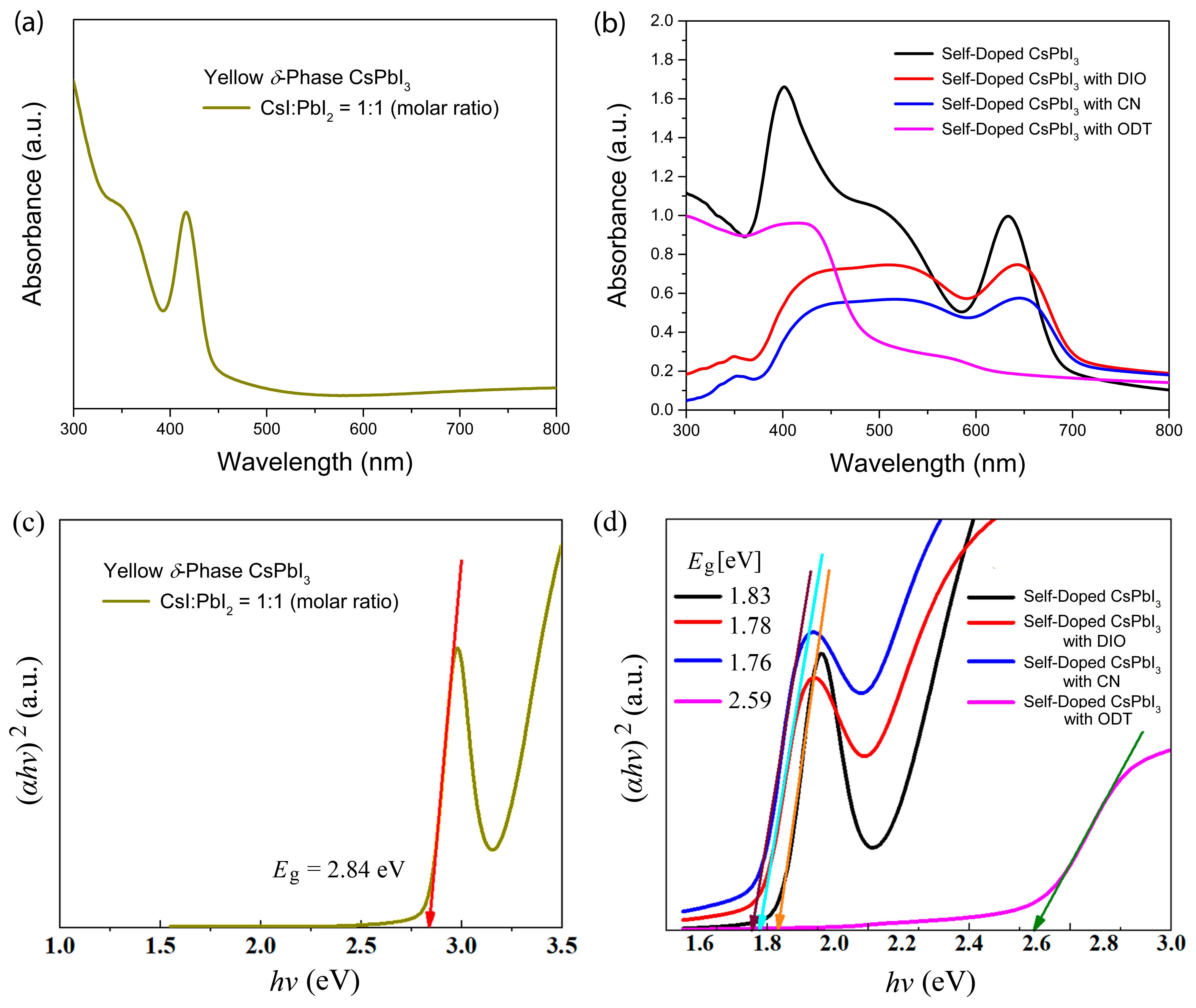
- Tauc, J. Optical properties and electronic structure of amorphous Ge and Si. Mater. Res. Bull. 1968, 3, 37–46. [Google Scholar] [CrossRef]
- Zhang, L.; Sun, C.; He, T.; Jiang, Y.; Wei, J.; Huang, Y.; Yuan, M. High-performance quasi-2D perovskite light-emitting diodes: From materials to devices. Light Sci. Appl. 2021, 10, 61. [Google Scholar] [CrossRef]
- Leung, T.L.; Ahmad, I.; Syed, A.A.; Ng, A.M.C.; Popović, J.; Djurišić, A.V. Stability of 2D and quasi-2D perovskite materials and devices. Commun. Mater. 2022, 3, 63. [Google Scholar] [CrossRef]
- Sheng, X.; Li, Y.; Xia, M.; Shi, E. Quasi-2D halide perovskite crystals and their optoelectronic applications. J. Mater. Chem. A 2022, 10, 19169–19183. [Google Scholar] [CrossRef]
- Protesescu, L.; Yakunin, S.; Bodnarchuk, M.I.; Krieg, F.; Caputo, R.; Hendon, C.H.; Yang, R.X.; Walsh, A.; Kovalenko, M.V. Nanocrystals of Cesium Lead Halide Perovskites (CsPbX3, X = Cl, Br, and I): Novel Optoelectronic Materials Showing Bright Emission with Wide Color Gamut. Nano Lett. 2015, 15, 3692–3696. [Google Scholar] [CrossRef] [PubMed]
- Straus, D.B.; Guo, S.; Cava, R.J. Kinetically Stable Single Crystals of Perovskite-Phase CsPbI3. J. Am. Chem. Soc. 2019, 141, 11435–11439. [Google Scholar] [CrossRef] [PubMed]
- Bhaumik, S.; Bruno, A.; Mhaisalkar, S. Broadband emission from zero-dimensional Cs4PbI6 perovskite nanocrystals. RSC Adv. 2020, 10, 13431–13436. [Google Scholar] [CrossRef] [PubMed]
- Kim, Y.G.; Kim, T.-Y.; Oh, J.H.; Choi, K.S.; Kim, Y.-J.; Kim, S.Y. Cesium lead iodide solar cells controlled by annealing temperature. Phys. Chem. Chem. Phys. 2017, 19, 6257–6263. [Google Scholar] [CrossRef] [PubMed]
- Wang, Y.; Zhang, T.; Kan, M.; Li, Y.; Wang, T.; Zhao, Y. Efficient a-CsPbI3 Photovoltaics with Surface Terminated Organic Cations. Joule 2018, 2, 2065–2075. [Google Scholar] [CrossRef]
- Yousaf, T.; Shahzad, N.; Sattar, A.; Tariq, M.A.; Hussain, N.; Khan, Z.S.; Javed, S.; Shahzad, M.I.; Pugliese, D. Performance of Cs-Doped Carbon-Based Perovskite Solar Cells in Ambient Environment. Energies 2023, 16, 4748. [Google Scholar] [CrossRef]
- Doumon, N.Y.; Wang, G.; Qiu, X.; Minnaard, A.J.; Chiechi, R.C.; Anton, L.J. 1,8-diiodooctane acts as a photo-acid in organic solar cells. Sci. Rep. 2019, 9, 4350. [Google Scholar] [CrossRef]
- Wu, Y.; Wang, Y.; Duan, J.; Yang, X.; Zhang, J.; Liu, L.; Tang, Q. Cluster effect of additives in precursors for inorganic perovskites solar cells. Electrochim. Acta 2019, 331, 135379. [Google Scholar] [CrossRef]
- Li, B.; Zhang, Y.; Fu, L.; Yu, T.; Zhou, S.; Zhang, L.; Yin, L. Surface passivation engineering strategy to fully-inorganic cubic CsPbI3 perovskites for high-performance solar cells. Nat. Commun. 2018, 9, 1076. [Google Scholar] [CrossRef]
- Cavallini, M.; Bracali, M.; Aloisi, G.; Guidelli, R. Electrochemical STM Investigation of 1,8-Octanedithiol Self-Assembled Monolayers on Ag(111) in Aqueous Solution. Langmuir 1999, 15, 3003–3006. [Google Scholar] [CrossRef]


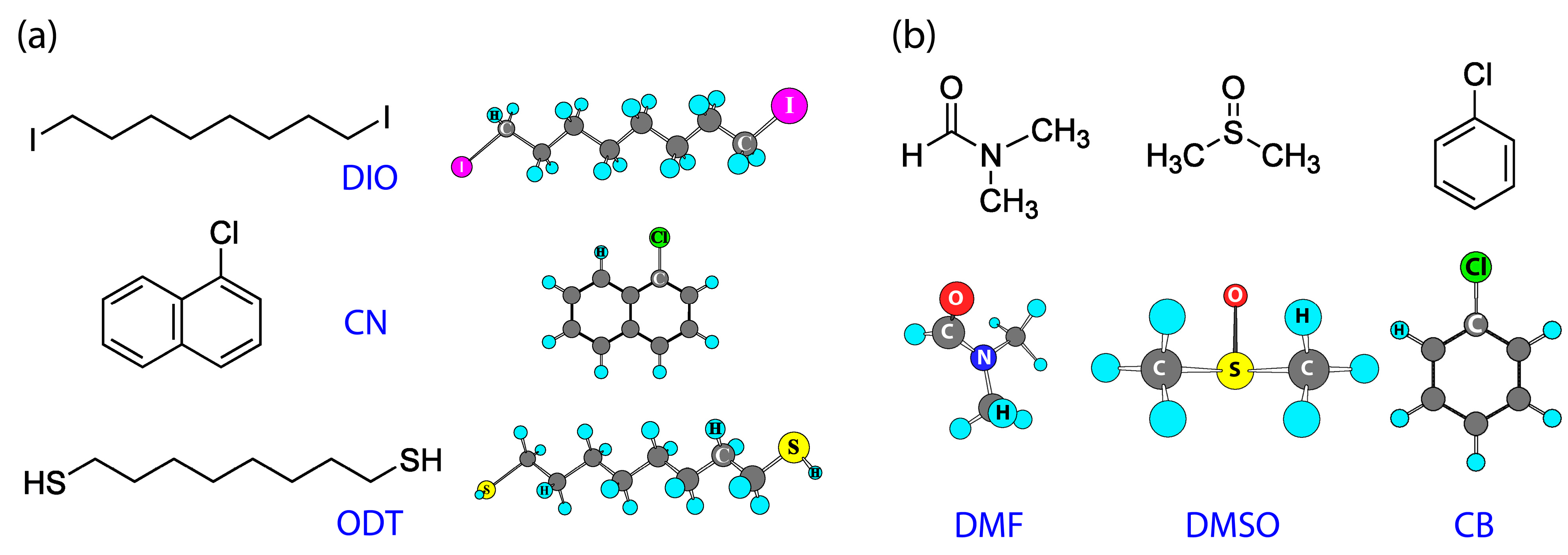
| Additive | Group | (J/mol) | Group Number | (J/mol) | (g/mol) | (g/cm3) | (cm3/mol) | b.p. (°C) | (MPa)1/2 | (cal/cm3)1/2 |
|---|---|---|---|---|---|---|---|---|---|---|
| DIO | -CH2- | 4190 | 8 | 71,620 | 366.02 | 0.818 | 447.5 | 167–169 | 19.0 | 9.3 |
| -I | 19,050 | 2 | ||||||||
| CN | -Cl | 12,990 | 1 | 58,056 | 162.62 | 1.194 | 136.2 | 111–113 | 20.7 | 10.1 |
| -CH=CH- | 10,200 | 3 | ||||||||
| >C=C(H)- | 4860 | 1 | ||||||||
| >C=C< | 9606 a | 1 | ||||||||
| ODT | -CH2- | 4190 | 8 | 77,050 | 178.36 | 0.970 | 183.9 | 269–270 | 18.8 | 9.2 |
| -S- | 8800 | 2 | ||||||||
| -H | 12,965 a | 2 |
| Solvent | (g/mol) | (g/cm3) | (cm3/mol) | b.p. (°C) | (MPa)1/2 | (cal/cm3)1/2 | DN (kcal/mol) |
|---|---|---|---|---|---|---|---|
| DMF | 70.09 | 0.948 | 73.9 | 153 | 24.8 | 12.1 | 26.6 |
| DMSO | 78.13 | 1.100 | 71.0 | 189 | 29.7 | 14.5 | 29.8 |
| CB | 112.56 | 1.110 | 101.4 | 132 | 19.5 | 9.5 | 3.3 |
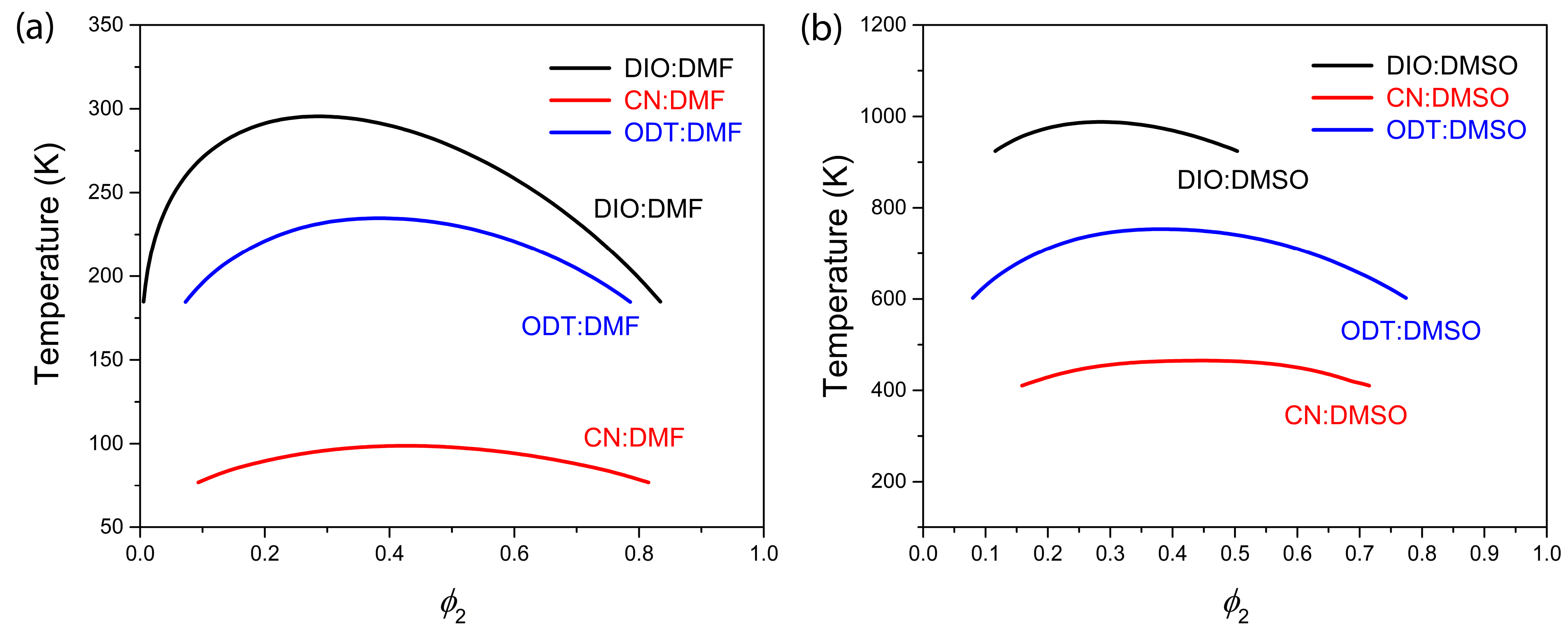
| System | DIO:DMF | CN:DMF | ODT:DMF | DIO:DMSO | CN:DMSO | ODT:DMSO |
|---|---|---|---|---|---|---|
| 291.6/T | 148.8/T | 312.8/T | 966.2/T | 691.8/T | 1003.7/T | |
| 6.1 | 1.8 | 2.5 | 6.3 | 1.9 | 2.5 |
Disclaimer/Publisher’s Note: The statements, opinions and data contained in all publications are solely those of the individual author(s) and contributor(s) and not of MDPI and/or the editor(s). MDPI and/or the editor(s) disclaim responsibility for any injury to people or property resulting from any ideas, methods, instructions or products referred to in the content. |
© 2023 by the authors. Licensee MDPI, Basel, Switzerland. This article is an open access article distributed under the terms and conditions of the Creative Commons Attribution (CC BY) license (https://creativecommons.org/licenses/by/4.0/).
Share and Cite
Kebede, T.; Abebe, M.; Mani, D.; Paduvilan, J.K.; Thottathi, L.; Thankappan, A.; Thomas, S.; Kamangar, S.; Shaik, A.S.; Badruddin, I.A.; et al. Phase Behavior and Role of Organic Additives for Self-Doped CsPbI3 Perovskite Semiconductor Thin Films. Micromachines 2023, 14, 1601. https://doi.org/10.3390/mi14081601
Kebede T, Abebe M, Mani D, Paduvilan JK, Thottathi L, Thankappan A, Thomas S, Kamangar S, Shaik AS, Badruddin IA, et al. Phase Behavior and Role of Organic Additives for Self-Doped CsPbI3 Perovskite Semiconductor Thin Films. Micromachines. 2023; 14(8):1601. https://doi.org/10.3390/mi14081601
Chicago/Turabian StyleKebede, Tamiru, Mulualem Abebe, Dhakshnamoorthy Mani, Jibin Keloth Paduvilan, Lishin Thottathi, Aparna Thankappan, Sabu Thomas, Sarfaraz Kamangar, Abdul Saddique Shaik, Irfan Anjum Badruddin, and et al. 2023. "Phase Behavior and Role of Organic Additives for Self-Doped CsPbI3 Perovskite Semiconductor Thin Films" Micromachines 14, no. 8: 1601. https://doi.org/10.3390/mi14081601
APA StyleKebede, T., Abebe, M., Mani, D., Paduvilan, J. K., Thottathi, L., Thankappan, A., Thomas, S., Kamangar, S., Shaik, A. S., Badruddin, I. A., Aga, F. G., & Kim, J. Y. (2023). Phase Behavior and Role of Organic Additives for Self-Doped CsPbI3 Perovskite Semiconductor Thin Films. Micromachines, 14(8), 1601. https://doi.org/10.3390/mi14081601