3.1. Components
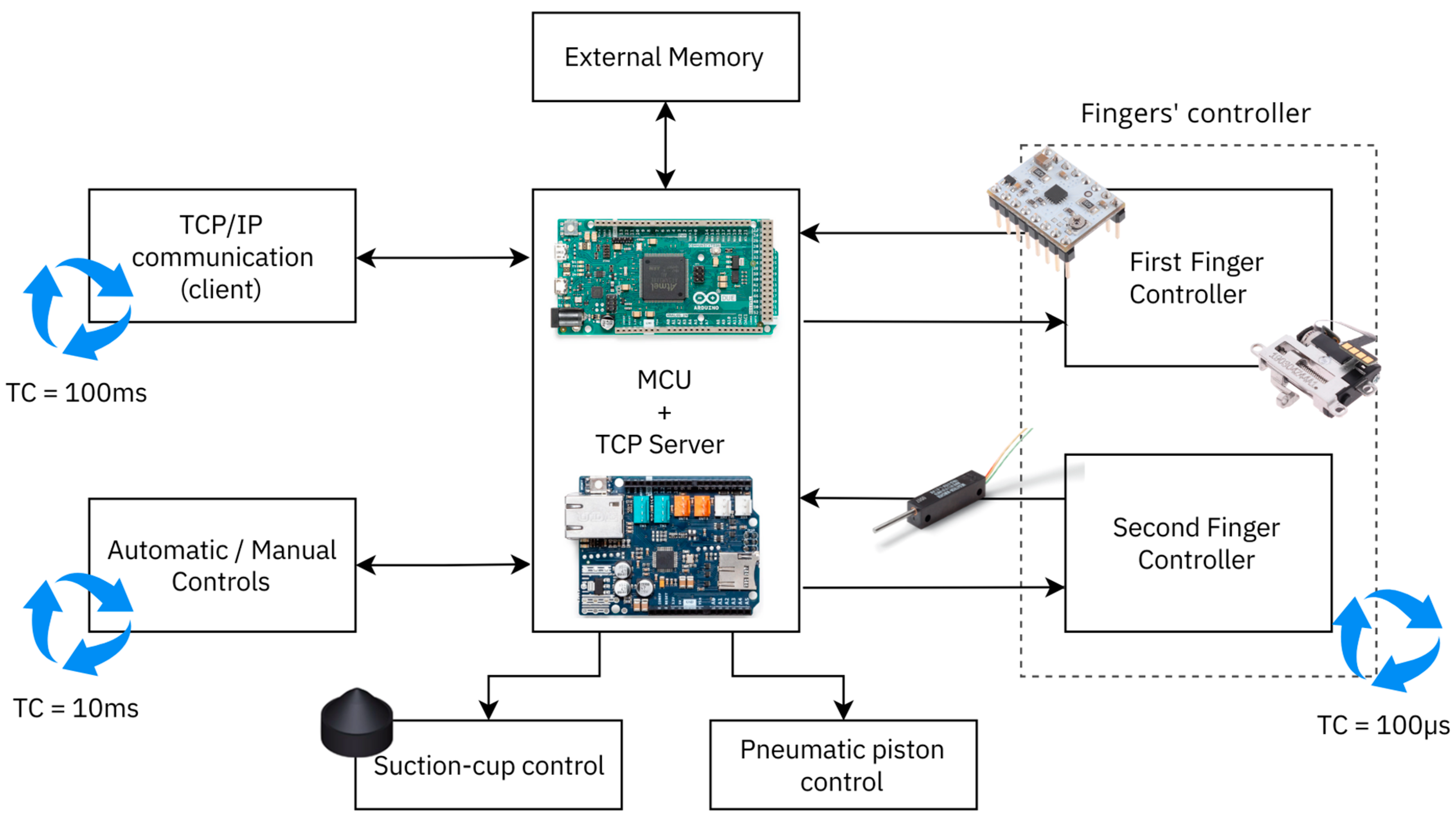
The controller was designed to control and manage all the micro-gripper functionalities, ensuring compliance with the project specifications reported in the previous section: open-loop control of the vertical lifting piston of the gripper fingers, on/off control of the suction vacuum, closed-loop position control of the two fingers independently, Ethernet TCP/IP communication for receiving commands and sending status messages, and external manual driving via the control panel or automatic one via digital signals. For this reason, the controller comprises several subsystems and components, as can be seen in the functional block scheme in
Figure 7.
The core of the control is the Microcontroller Unit (MCU), which consists of an Arduino Due, equipped with an Ethernet Shield v.2. The choice of this MCU, in addition to its great flexibility, modularity, and ease of use, depended mainly on the high computational speed, as it runs at 84 Mhz, the high number of digital I/O pins, and the availability of a 12-bit ADC. Its high clock frequency made it possible to create a pseudo-real-time multi-thread control system with different cycle times and to use its timers to command drivers both in open and closed loops. Three threads were created: the first one for the TCP/IP communication running with a period of 100 ms, the second one for the fingers’ controls, running with a period of 100 µs, and the last one for the external command signals that read input digital signals or the pushbutton states, running with a period of 10 ms.
An external EEPROM was used to store the basic configuration parameters to handle possible undesirable effects caused by a power failure or controller shutdown and restart. The 256 K I2C CMOS Serial EEPROM 24LC256 from Microchip was chosen.
The functionality of the gripper can be managed in three different modes: manual mode via manual pushbuttons, automatic mode via digital input signals, and communication mode via TCP/IP communication. The communication mode is always enabled, while a selector switch was equipped on the controller to switch between automatic and manual modes. The signal inputs for automatic handling mode were equipped with opto-isolated static relays to decouple the gripper control system circuit to the external driving circuit (e.g., robot controller, PLC, …) where the digital control signals were output.
The suction vacuum and the vertical piston position were controlled by two normally closed 3-2 solenoid valves, driven, respectively, by two static opto-isolated relays that bring the correct voltage to the two solenoids. Two digital outputs of the microcontroller were used to change the state of the static relays as on/off controls.
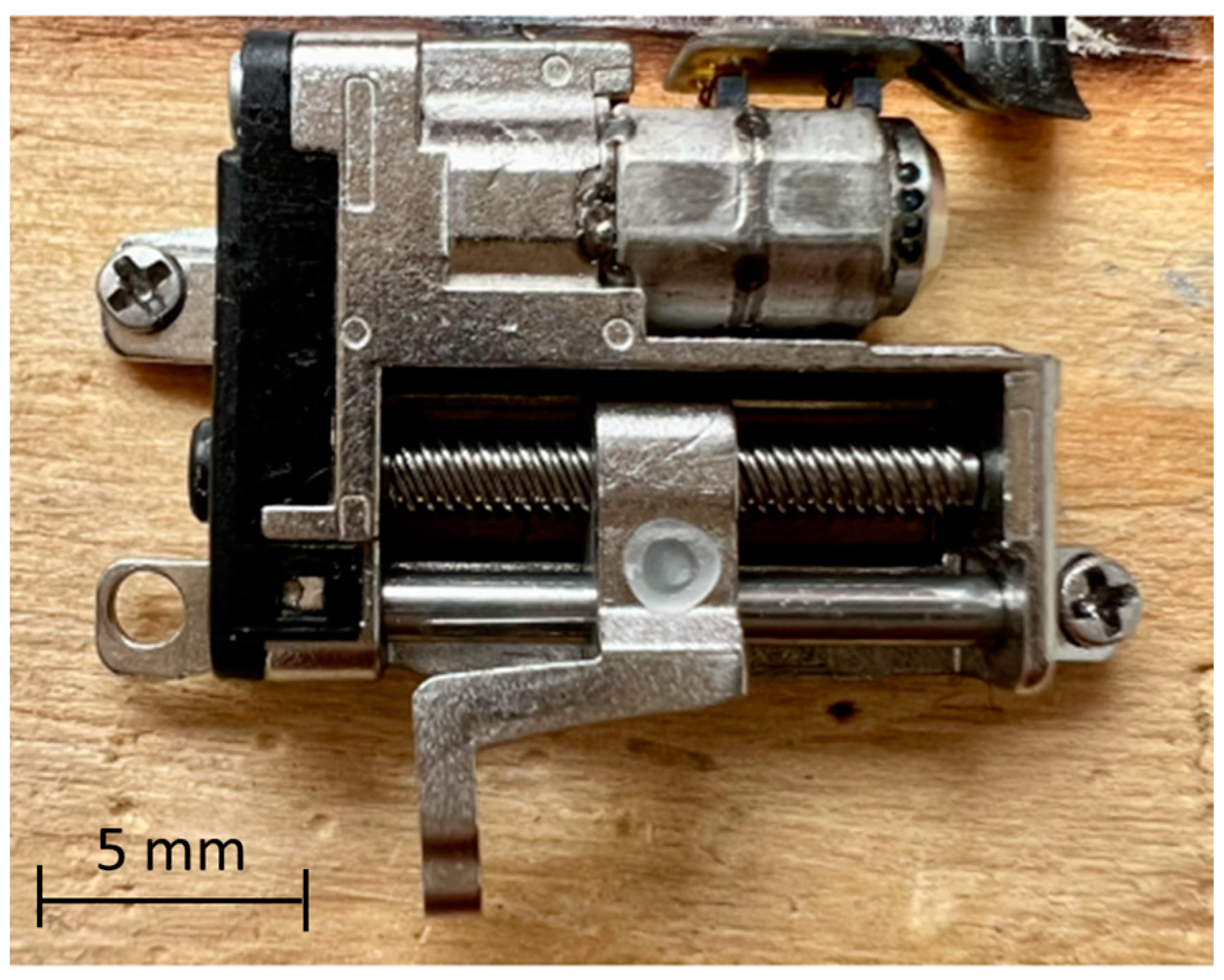
Finally, the elements that make up the finger controllers were two STSPIN220 Low-Voltage Stepper Motor Drivers, two precision linear potentiometers, and two linear axes mechanically connected to the gripper fingers, respectively, composed by a micro-claw pole stepper motor and a mechanism of transmission and transformation of motion (i.e., gearbox and screw drive). The chosen drivers allowed the stepper motors to be driven with the STEP/DIR logic at a high frequency and to increase the step resolution using a micro-stepping down to 1/256th of a step. In this paper, a micro-stepping of 1/4th was used. The resulting linear step of the linear axes was 6.25 µm/step. The precision linear potentiometer provided position feedback for the closed-loop control through PID controllers.
3.2. Control Algorithm
The gripper components that we wanted to be controlled were the piston for movement along the vertical axis, the suction cup, and the fingers. As said, an open loop and an on/off control were implemented, respectively, for the first two components by exploiting two solenoid valves and two relays for power conversion. Differently, a more advanced control was implemented for the fingers that allowed both open-loop and closed-loop driving, exploiting the previously described driver with a STEP/DIR driving mode. An open-loop control algorithm with a trapezoidal speed profile following was implemented, exploiting the method described in [
40]. The method allowed the generation of a real-time trapezoidal/triangular velocity profile for stepper motors with an MCU. Then, knowing the transmission ratio of the linear axis, it was possible to calculate the rotative motion law of the motor to perform the desired linear movement of the finger. The trapezoidal velocity profile was completely defined by four of the following parameters: total displacement ∆S [rad], total motion time ∆T [s], acceleration A [rad/s
2], deceleration D [rad/s
2], maximum speed V
max [rad/s], and
, with
where
is the ratio between the
-th section time of the law of motion and ∆T, and
. The profile was approximated with a sequence of speed steps. Each step has a certain duration, corresponding to the interval between one step of the motor and the next. As the speed increased (or decreased), i.e., in the ramps of the speed profile, the delay between consecutive steps decreased (or increased). Instead, the delay remained constant in the profile section at a constant speed. The algorithm can be implemented by exploiting the timers of the MCU. Through appropriate approximations, the following equations were obtained:
Equation (1) describes the delay between consecutive steps , obtained with a 32-bit timer count c [-], with a timer frequency f [Hz]. Equation (2) expresses the motor speed obtained with a timer count c and a motor step angle [rad/step]. Equations (3) and (4) express the first count of the timer and the -th subsequent counts needed to obtain the speed ramp, where is the sequence index, [rad/s2] is the acceleration in the first section, and determines the acceleration/deceleration. It increments with for constant acceleration, i.e., , while it starts from a negative value and increments for constant deceleration. Indeed, Equation (4) with can be used to ramp any speed down to stop in the final steps of a movement of steps. Equation (5) expresses the step number as a function of speed and acceleration and can be used to obtain the number of steps required to reach a desired speed with a desired acceleration, starting from a standstill motor. The value thus calculated also corresponds to the number of steps required to reach zero speed, starting from velocity with desired deceleration (in absolute value). The number of steps needed to reach a given speed is inversely proportional to the acceleration. This makes it possible to change the acceleration at a point on the ramp by changing the step number in the ramp algorithm, by using Equation (6), where a half-step is added to -values for better accuracy.
Then, starting from the parameters that characterize the law of motion, the total number of steps to be performed in time ∆T is first derived to make the total displacement ∆S: . Then, Equation (5) derives the number of acceleration and deceleration steps from the values of maximum speed, acceleration, and deceleration, which are imposed as parameters of the law of motion. Finally, the number of steps of the constant velocity section is calculated using subtraction. During the movement, only the time between consecutive steps is calculated, and it is defined by the numerical sequence of the timer count .
The open-loop control algorithm takes advantage of this method of generating speed ramps to produce a trapezoidal law of motion in real-time for the fingers, in which a 32-bit timer unit manages the generation of the train of pulses (i.e., a square wave with a duty cycle of 50%) input to the motor driver, with a variable frequency, calculated through the algorithm at each timer interrupt. The maximum driving frequency of the open-loop control was 42 [MHz], but it was limited by the maximum frequency (i.e., maximum speed of the stepper motor) allowed by the motor, equal to 24 [kHz]. During the constant speed section, the algorithm was suspended for the desired number of steps, calculated in advance, knowing the number of steps needed to perform the motion and the number of steps needed for the acceleration and deceleration phases.
Instead, closed-loop position control was performed using a PID controller, with trapezoidal law of motion tracking. Position feedback was obtained using the precision linear potentiometer.
3.2.1. Feedback Signal Filtering and Sensor Calibration
Before the closed-loop control could be developed, it was necessary to analyze the position feedback acquisition system. As mentioned, two potentiometers with a measuring range of 11 mm acquired the position feedback for the two fingers. As introduced in
Section 2.1, the 12-bit ADC included in the Arduino Due board was used for digital conversion, and then the systems acquisition resolution obtained was 2.68 µm. The first step that needed to be carried out was the analysis of the feedback signal to evaluate the measurement noise. Raw data were acquired from different positions of the two linear potentiometers placed on the fingers to evaluate the standard deviation of the measurement. The chosen positions were the closed pose, the open pose, and a position in the middle of the full range of movement.
Table 2 shows the values of the standard deviation measured for the two potentiometers in the different positions. It is worth noting that the maximum value was obtained in the open position when the voltage signal was lower. A second-order low-pass filter was designed to reduce the maximum standard deviation. A 3 dB cutoff frequency of 50 [Hz] was selected. The standard deviation values obtained from the same filtered signals as before are shown in
Table 3. By comparing the two tables, it can be seen that the standard deviation was reduced by 87% for the first finger and by 89% for the second one. Knowing the resolution of the acquisition system, the maximum standard deviations of the filtered potentiometer signals can be converted into micrometers, obtaining a value of 6.57 [µm] for the first finger and a value of 6.52 [µm] for the second one.
To perform the sensor calibration with a high resolution, it was necessary to verify the maximum stroke of the linear axes. An absolute linear indicator (i.e., Mitutoyo Digimatic Indicator ID-C112B No. 543-250B) with a linear resolution of 0.001 [mm], a measuring range of 12.7 [mm], and an accuracy of 0.003 [mm] was used as an external measurement system. The stroke was obtained by measuring the linear displacement of the axis from the first limit switch (corresponding to the fully opened position) to the second one (corresponding to the fully closed position) for both fingers, resulting in a maximum range of movement of 9119 [µm] for the first finger and 9086 [µm] for the second one.
Finally, the linear calibration of the sensor was performed by developing an automatic routine into the microcontroller. The controller acquired raw values of the potentiometers from the ADC at the extremes of the motion range (i.e., limit switches) and then computed the linear calibration, knowing the range of movement of the fingers saved into the memory.
3.2.2. Mechanical Backlash
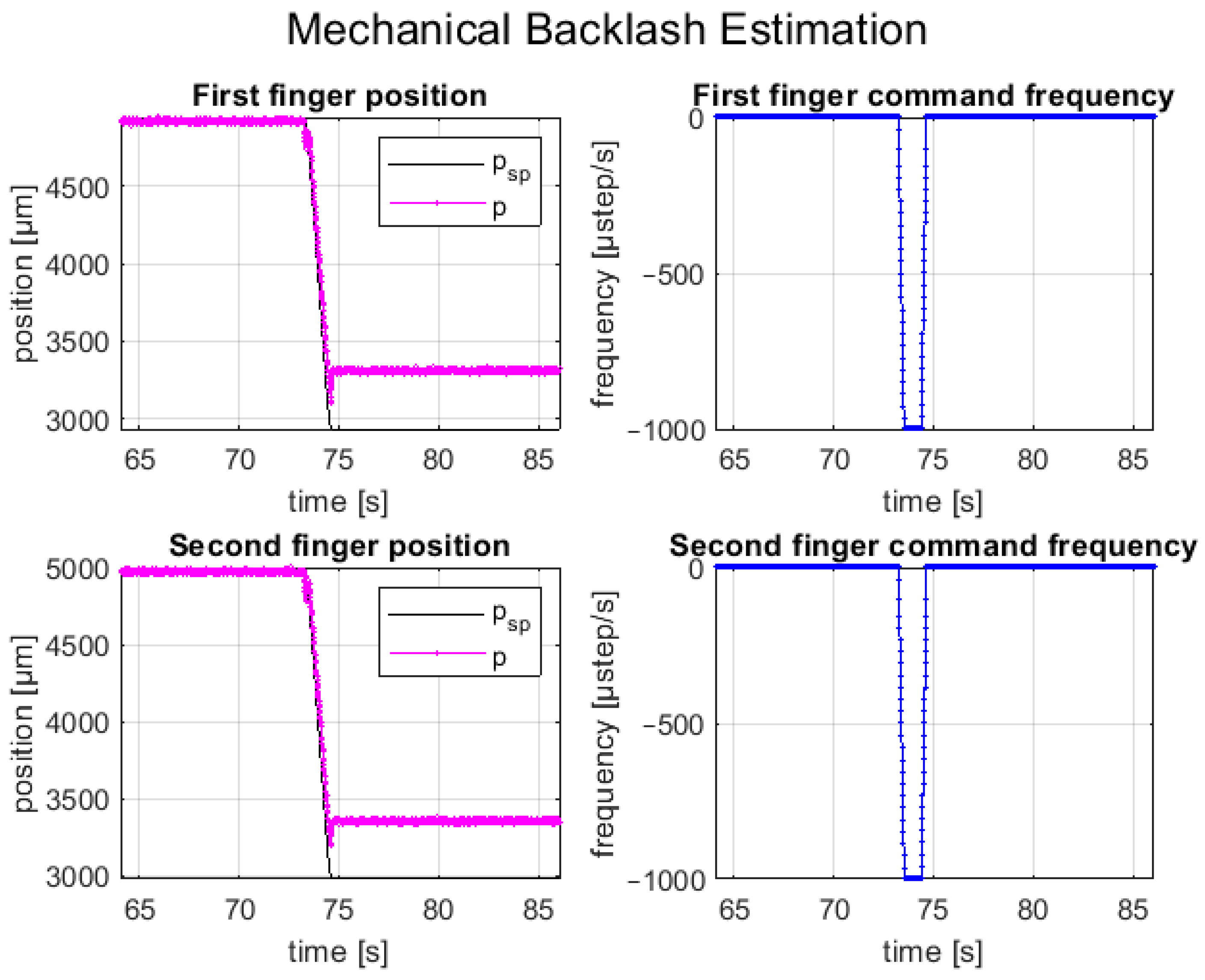
An experimental test was carried out to evaluate the mechanical backlash of the two linear axes of the fingers. The test for both axes involved several repetitions of a first initialization open-loop movement in one direction and a second open-loop movement in the opposite direction. This choice was made because the preliminary experiment showed that the mechanical backlash was more significant after changing the movement direction; therefore, it represented the worst condition. To avoid step loss due to the load torque, the tests were carried out by setting the maximum step frequency equal to 1 kHz, to assure a suitable motor torque. In this way, the steady-state error position of the tests was mainly caused by the mechanical backlash of the linear axis. Furthermore, a short displacement was commanded, in such a way that the error related to the theoretical step angle tolerance was reduced, and the main component of the steady-state error was the mechanical backlash.
Figure 8 shows the setpoint position (
psp), the feedback position (
p), and the commanded step frequency of both fingers during a trial, consisting of an opening movement with a relative displacement of 2 mm and
. It is worth noting that the feedback positions do not reach the theoretical positions due to the mechanical backlash of the linear axes.
Different trials were carried out, and the maximum mechanical backlash measured for both finger axes is reported in
Table 4.
3.2.3. Closed-Loop Control Algorithm Development
Stepper motors are prone to losing steps, and the backlash axis causes position errors. These issues can be prevented by oversizing the motor or implementing closed-loop control with position feedback. Closed-loop control offers the advantage of detecting and correcting position errors while optimizing torque selection and energy consumption.
One closed-loop control technique is step-loss compensation, where the motor operates in an open loop while position feedback tracks the movement. Missing steps are counted and executed at the end of the motion profile to reach the desired position. However, this method only corrects the position at the end of the profile.
Load position control continuously monitors the position and generates an error signal for real-time adjustments during the motion profile. While the motor operates in micro-stepping mode as if it were in an open loop, it closely follows the motion profile.
Field-oriented control, the most advanced method, treats the motor as a two-phase brushless motor. Instead of supplying the maximum current, a control loop with a PID controller determines the required torque for precise movement, deriving the current magnitude from it. This method improves efficiency, reduces heating, extends motor life, and eliminates resonance issues. It is also known as vector control, which involves transforming the coordinates of the motor’s electric and magnetic fields to a rotating reference system aligned with the rotor. This allows AC motors to be driven similar to DC motors with brushes. This method is also called vector control in the literature. A comprehensive explanation of field-oriented control can be derived from [
41,
42].
Sensor-less control relies on back-electromotive force (back-emf) to determine the rotor position. Some cases of study were analyzed [
43,
44,
45]. Back-emf is used to estimate and control the load angle, aiming to maximize torque output. However, this control method is unsafe since back-emf can only be measured at zero-crossing points of the current, and accurate estimation relies on a reliable motor model. Also, it is challenging to implement it and lacks certainty in rotor position determination.
Considering the complexity and model requirements of existing closed-loop control methods, a different technique was introduced in the paper. The developed closed-loop control strategy does not require detailed knowledge of the motor’s physical model and its design parameters, making it suitable for use with low-cost stepper motors where some specific design data may be not provided by the manufacturer while allowing high positioning precision suitable for the micro-manipulation of SMT components. It employs position feedback control with a PID controller, taking the position error as input and generating the step pulse command for the stepper motor, aided by speed feedforward. The speed is converted to a stepping frequency and sent to a low-cost stepper motor driver using the STEP/DIR interface. The driver limits the maximum current and maintains the desired current level, defining the micro-stepping position through an internal closed-loop circuit. This technique offers an alternative approach to achieve effective closed-loop control without relying heavily on complex motor models.
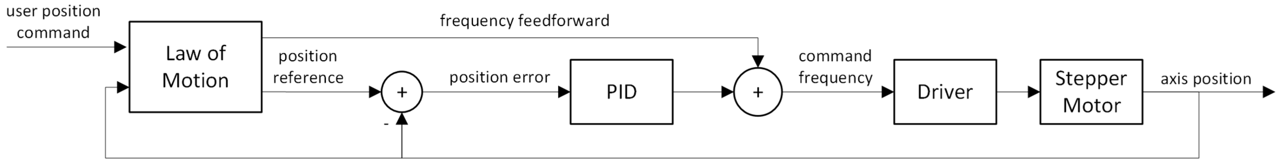
The closed-loop position control scheme was designed and implemented to synchronize and control the motions of the fingers with high precision, avoiding position errors due to mechanical backslash of the axes and step loss of the stepper motors. As said, a decentralized control was realized for the two axes of the fingers, implementing a position control closed-loop for each axis, as shown in
Figure 9. The motion law generation block, the feedback acquisition, and the generation of the control variable were carried out internally in the Arduino Due microcontroller. The block that defines the trapezoidal law of motion consists of a state machine, which outputs the desired value for position and velocity as time changes. The states represent the different sections of the law of motion (i.e., acceleration, constant speed, deceleration, and stop), and the transition between one and the following depends on the elapsed time. The position error between the theoretical position of the finger axis and the actual one measured by the linear potentiometer is input to the PID controller. Moreover, an anti-windup compensation for the integrator term of the PID controller was implemented with back-calculation. The controller only acts if the error exceeds a previously set control positioning tolerance, which depends mainly on the position feedback measurement maximum error (i.e., maximum standard deviation of the position measurements), the step size of the motor, and the mechanical backlash. The control tolerance prevents unwanted chattering in the control variable (i.e., the driver input frequency), which could damage the motor and reduce its lifetime. The control tolerance was set to ±50 µm after carrying out experimental closed-loop motion tests.
A speed feedforward action was also introduced to improve the setpoint tracking; therefore, the step frequency of the motor was given by the sum between the output of the PID controller and the feedforward action. In closed-loop circuits, the maximum driving frequency is lower than in open-loop circuits and is equal to 15 [kHz], obtained by experimental tests, above which the synchronization of the two fingers cannot be guaranteed, as a delay of the controller can be observed. The MCU generates the driving square wave at the desired frequency by exploiting a timer unit with a maximum output frequency of 42 MHz and is sent as input to the STEP pin of the driver. The movement direction is commanded with the DIR pin of the driver, based on the sign of the command frequency. Finally, position feedback is acquired by the ADC, which measures the digital voltage value of the linear potentiometer.
A suitable strategy was adopted to cope with external disturbances acting on the axes or the fingers, such as an external force moving a finger when it is stopped or a finger colliding with the external environment and stopping when it is moving. If the movement was already initiated, the new position and speed, outputs of the law of motion block, are computed; then, a comparison between the starting absolute position error and the actual error is made. If the error increased, a new law of motion is computed. In case the movement was not started yet (i.e., the position reference is constant, and the feedforward action is null), for little position errors, the PID controller is responsible to reject the disturbances. If the position error leads the PID controller output over the maximum starting frequency of the stepper motor, a new law of motion is computed starting at the actual axis position to avoid the stepper motor stall.
When the position error increases beyond a stall threshold, set equal to the estimated mechanical backlash of the axis, the motion is stopped to prevent damage. This method, known as collision or stall detection, is very useful to prevent damage.
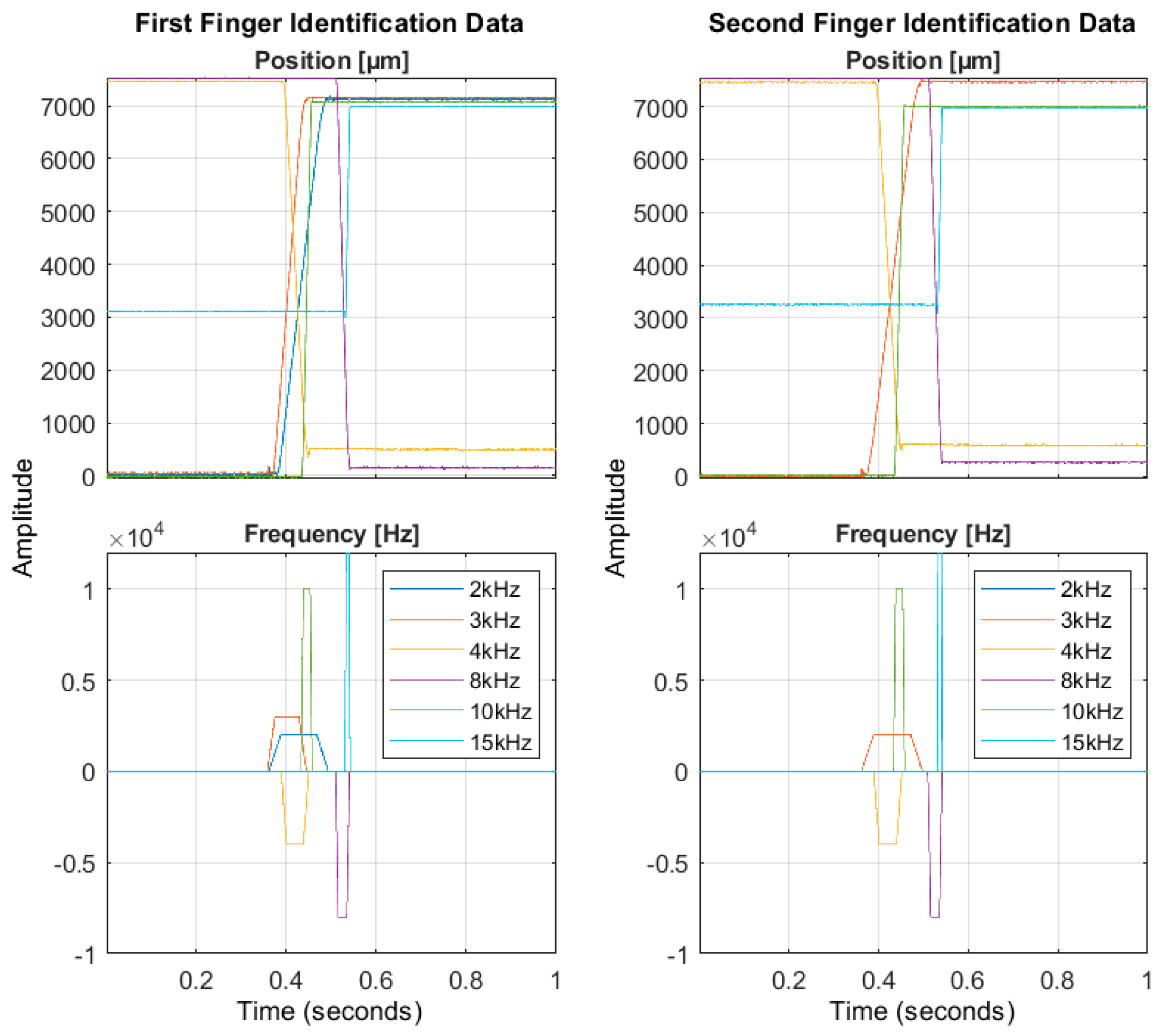
To fine-tune the PID controllers of the axes, it was necessary first to perform the linear system identification test. A time-domain impulse-response identification was performed for each axis, carrying out several open-loop motion cycles. In particular, for each motion cycle, a trapezoidal speed was set as system input, and the reached output positions were acquired with a sample time of 0.5 ms using the calibrated potentiometer. A total of eight cycles were executed for each finger axis, varying the maximum motion speed in the range of 3–24 mm/s and the driving time in the range of 0.4–3 s. Merging six test trials, chosen randomly among those performed, first-order transfer functions were estimated for the axes using the MATLAB System Identification toolbox. Then, the validation of the system identification was carried out by exploiting the remaining two trials.
Figure 10 shows the chosen identification trials for both axes: the frequency data represent the system input, and the position data represent the system output.
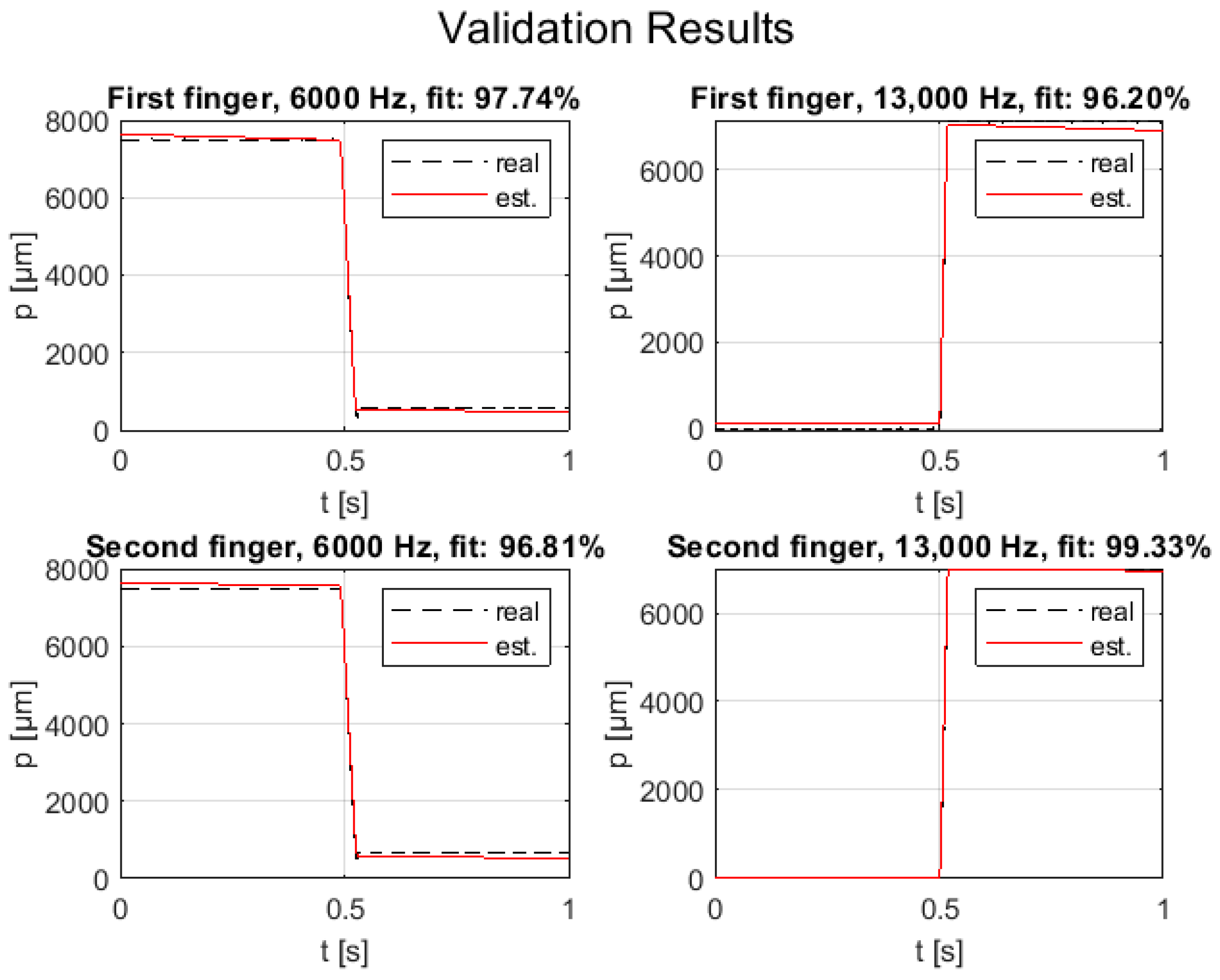
Figure 11 shows the position estimation by the identified model (i.e., first-order transfer function response, expressed in Equation (7)) using the input data of validation trials for both axes. It is worth noting that the model response fits the system dynamic of 96% in the worst case for both axes. The first-order model constants for the finger axes are reported in
Table 5 and the transfer function is:
Finally, the tuning of the PID controllers was performed using the MATLAB PID tuner toolbox. A PI controller was selected for both axes, setting the robustness to the maximum value to avoid unwanted overshoots and increasing the performance as much as possible to improve the setpoint tracking and noise rejection trade-off. The PID controller values for the two finger axes are reported in
Table 6 and the transfer function is:
3.2.4. Control Performance Assessment
Experimental tests were executed to assess the positioning and synchronization performance of the closed-loop motion control designed for the gripper fingers.
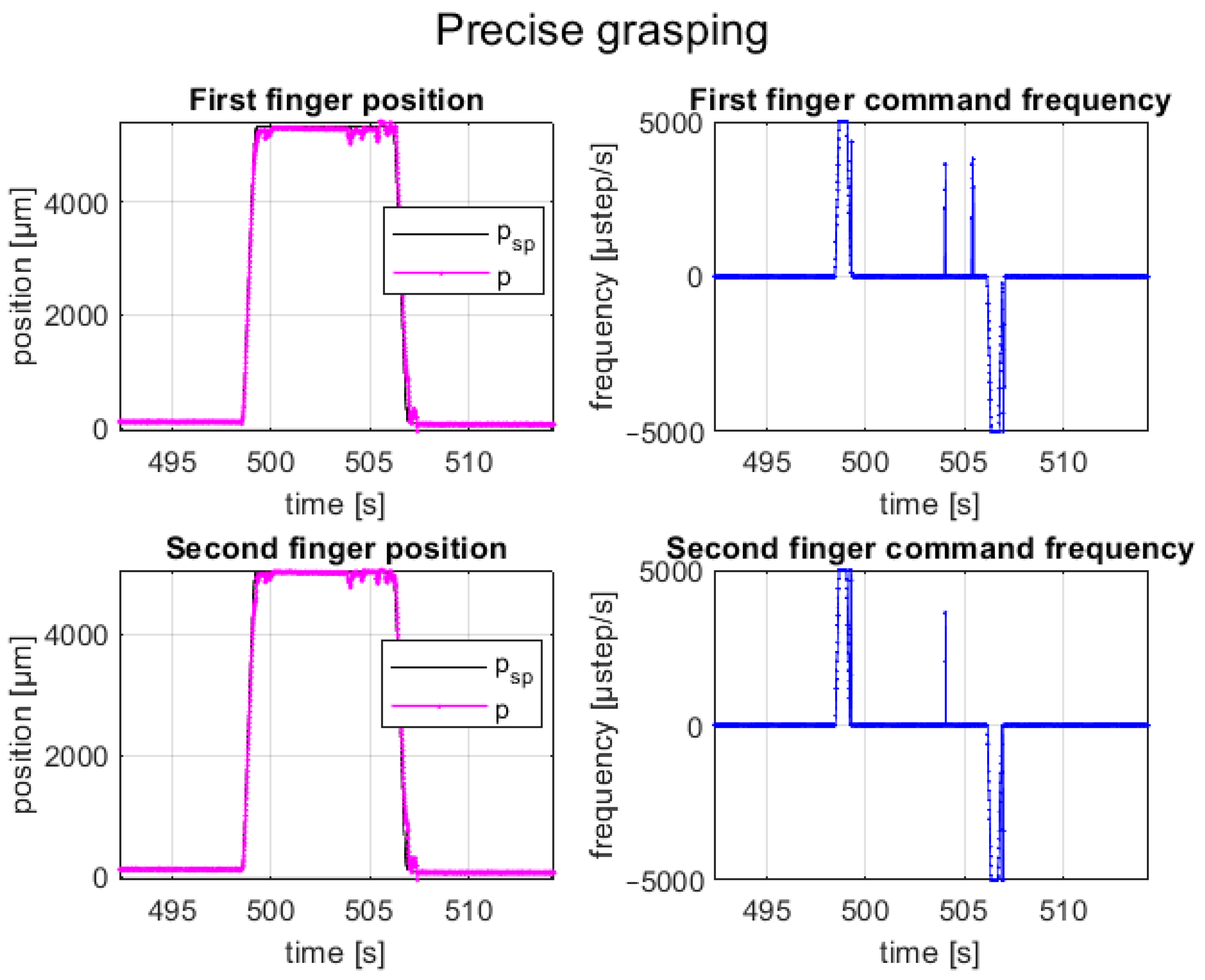
Firstly, the control capability of setpoint tracking was assessed with experimental tests. Several repetitions of picking and releasing cycles of sample SMT components (i.e., a BGA package with the size of 8 × 6 × 0.8 mm and a 1005 resistor with the size of 1 × 0.5 mm, both with a prismatic shape) were executed. The selected samples represent the minimum and maximum dimensions of the components that the designed gripper can handle. For each test, the setpoint tracking error and the time delay error (i.e., finger motion synchronization error) were computed, and finally, the error means and the standard deviations were calculated.
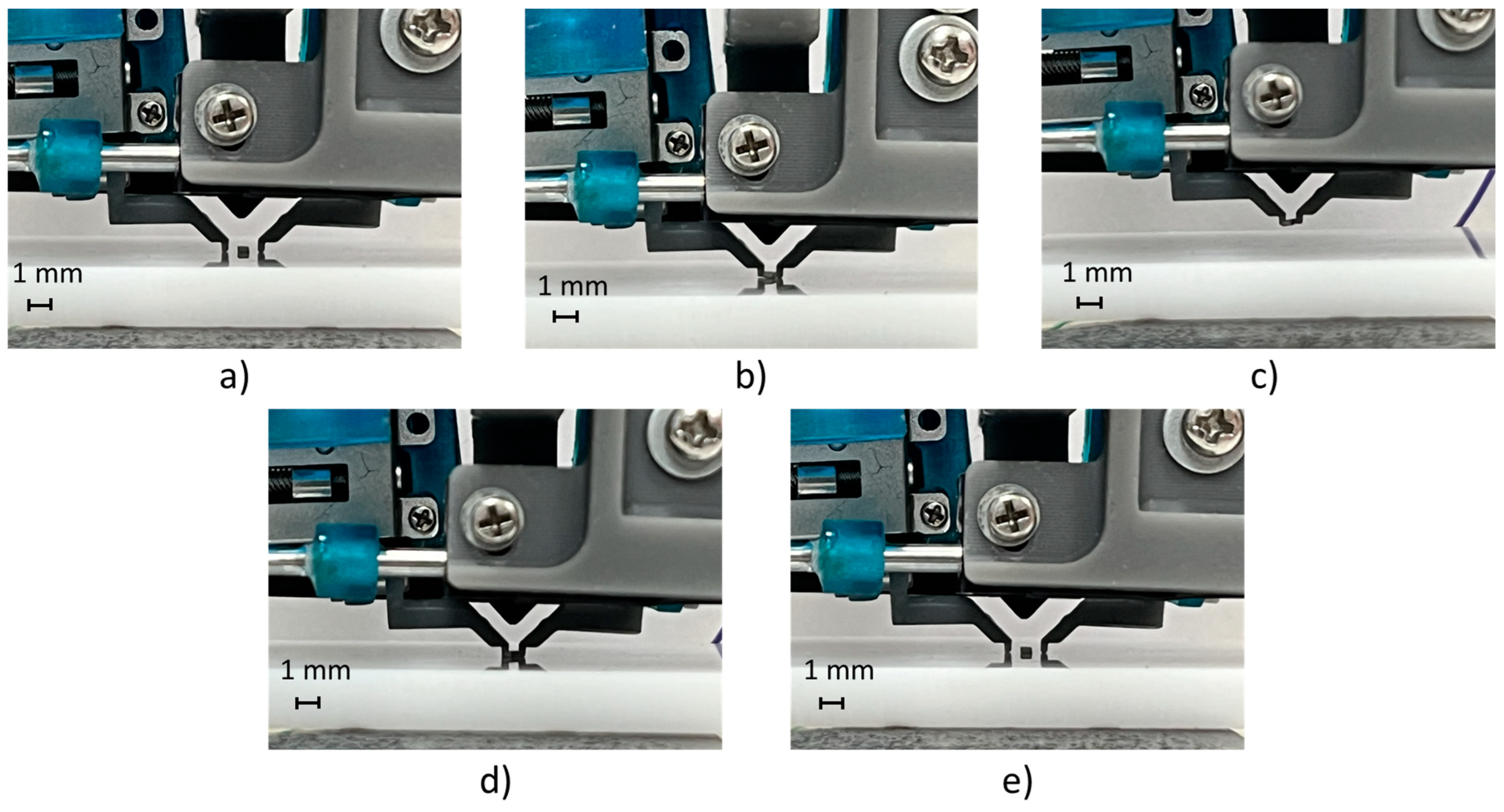
A test cycle emulated the pick-and-place task of an SMT component; it composed of a closed-loop motion of finger axes in precise positions (e.g., obtained by identifying the component size with a vision system or knowing the component size by data sheet) for picking the component, an upward movement of the gripper fingers (e.g., by a robot or gripper piston), a downward movement (e.g., by a robot or gripper piston), and a closed-loop motion of finger axes in precise positions for releasing the component on the substrate. The grasping and releasing cycles of the BGA component are shown in
Figure 12, and its setpoint tracking plots are shown in
Figure 13. The represented trial consisted of a relative displacement (opening and closing) of 5.2 mm for the first axis and 4.9 mm for the second axis, with a maximum step frequency of 5 kHz for both fingers in both directions, with
.
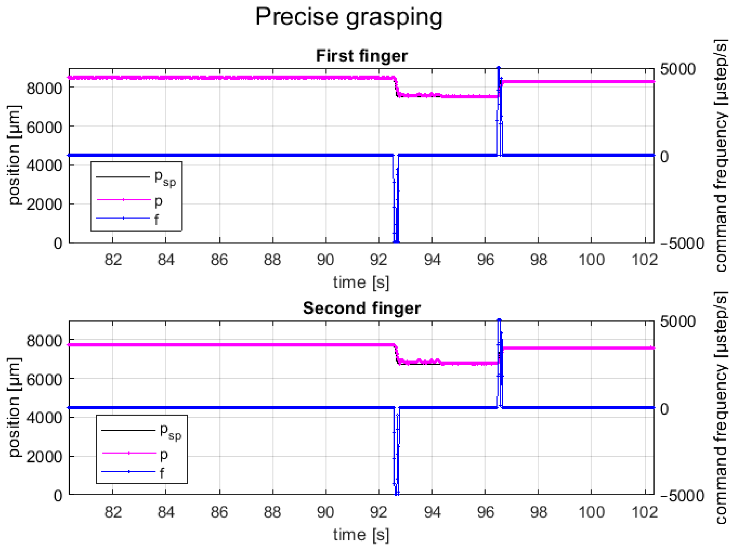
Instead,
Figure 14 shows the picking and releasing cycles of a 1005 resistor component, which is the smallest component that the gripper can manipulate, while the related setpoint tracking plots for both fingers are shown in
Figure 15. In this case, the trial consisted of a relative displacement (opening and closing) of 0.8 mm for each finger, with a maximum step frequency of 5 kHz for both fingers in both directions, with
.
It can be seen that the feedback position of the closed-control faithfully follows the setpoint position for both finger axes with a positioning error of less than ±50 µm (i.e., control tolerance); moreover, the motions of finger axes are completely synchronized with a time delay error less than 30 ms.
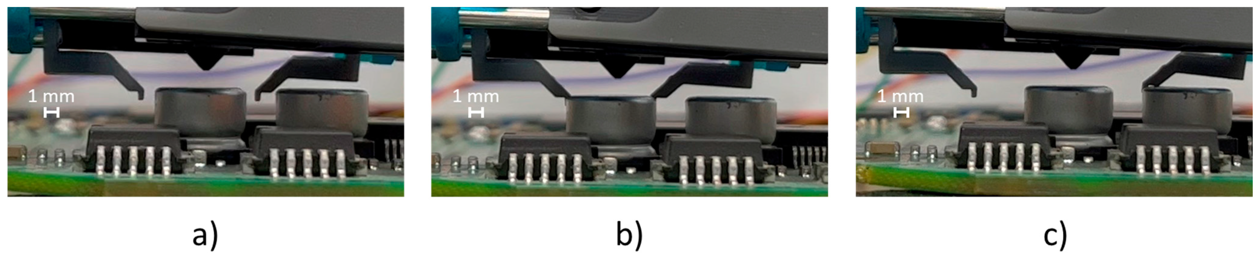
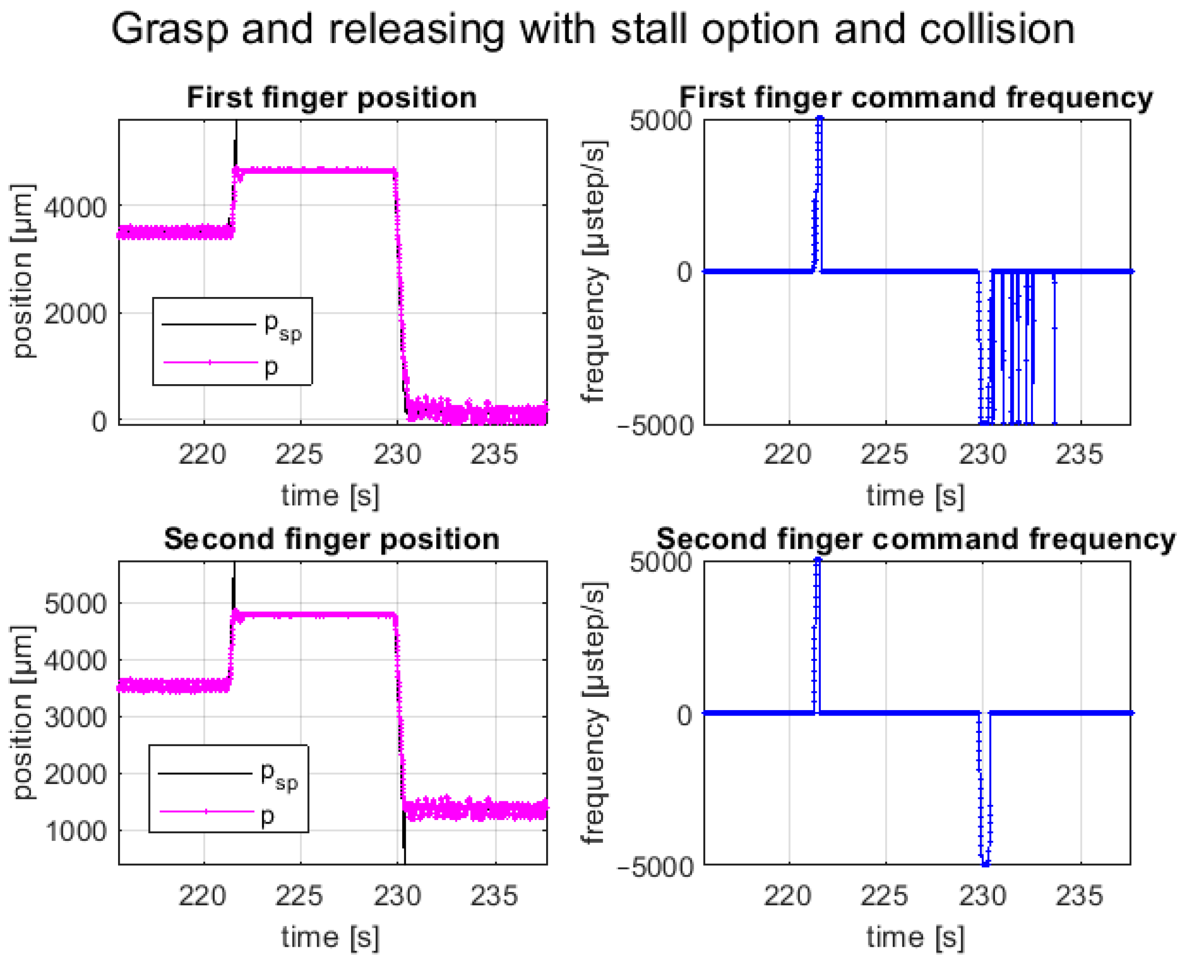
The second test consists of several repetitions of picking and releasing operations, using the stall detection option to detect the component in the picking phase and collision with the environment in the releasing phase. This option can be enabled independently for the two fingers or dependently, i.e., in the presence of a stall detection for a finger, both are stopped. The first option was selected to perform this test.
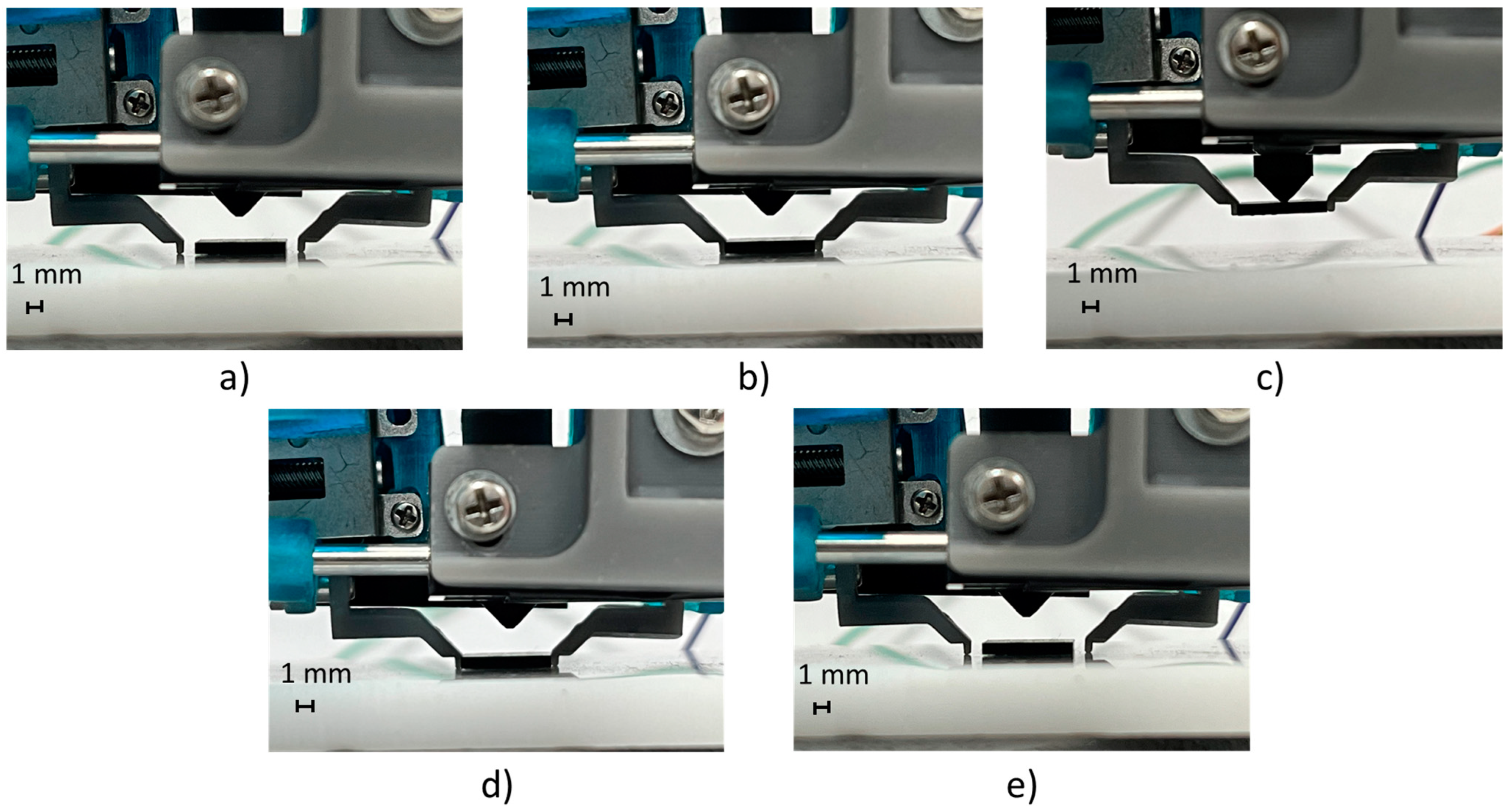
A total closure of the fingers was commanded to pick the component (i.e., electrolytic SMT capacitor with a size of 6 × 8 mm and a cylindrical shape); once the fingers collided with the component, they stopped and held the component in place due to the holding torque of the motor. The releasing phase was evaluated by simulating a collision of a finger with a component mounted on an electronic board during the full opening of the fingers. Once the finger collided with the obstacle, the controller recognized the stall and stopped both fingers in place. The picking and releasing cycles of the sample component with the stall detection option enabled are shown in
Figure 16. The position tracking plots are shown in
Figure 17. The represented trial consisted of a movement with a maximum step frequency of 5 kHz for both fingers in both directions, with
. As explained before, a full close motion was commanded, resulting in a relative movement of 5.6 mm, as the starting position was not fully opened. Instead, for the releasing phase, a movement of the full stroke of 9.1 mm was commanded. It is worth noting, that when the stall occurred, the setpoint position (black line) increased until the stall threshold was reached, and then, the setpoint was fixed to the current position and the law of motion was stopped.
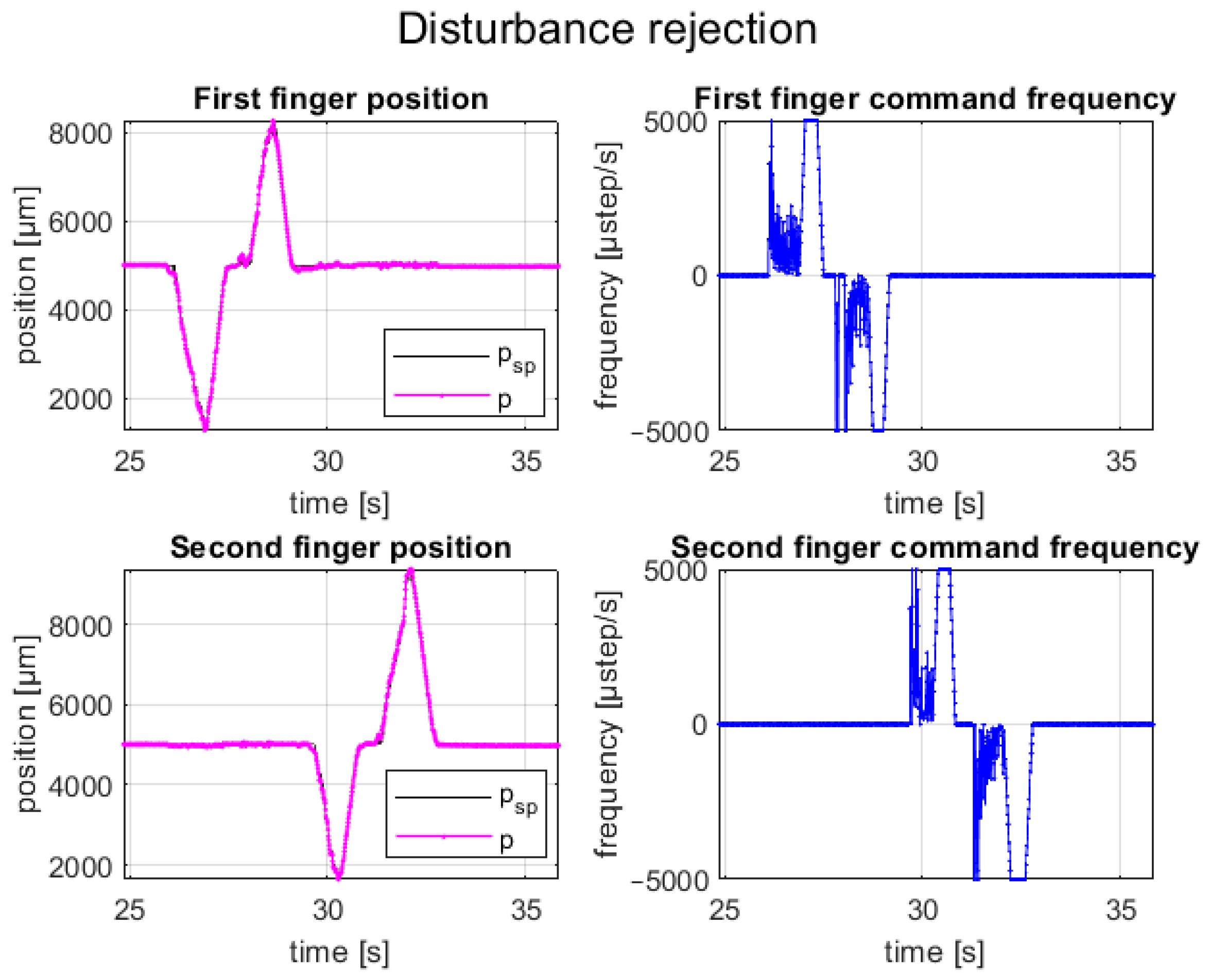
Another test performed concerns the disturbance rejection of the closed-loop control. External forces were applied in two different time instants to the fingers, and the system dynamics were observed. The controller reacted by recalculating the law of motion until the external disturbance disappeared, returning the system to the setpoint positions.
Figure 18 shows the position tracking during the disturbance rejection test. The behavior was the same for both fingers and for both open and close directions. First, when the external force was applied, the controller computed a new law of motion until the error increased; then, as soon as the external force was removed, the controller restored the setpoint position following the last computed law of motion, as shown in
Figure 18. The new law of motion was computed based on the configuration stored in the memory. As explained before, when the law of motion was computed, a new motion started from the actual position to correct the number of steps that need to be executed to restore the position and avoid an excessive starting speed. The plot also shows that when the external force was removed, the last computed law of motion followed as expected.
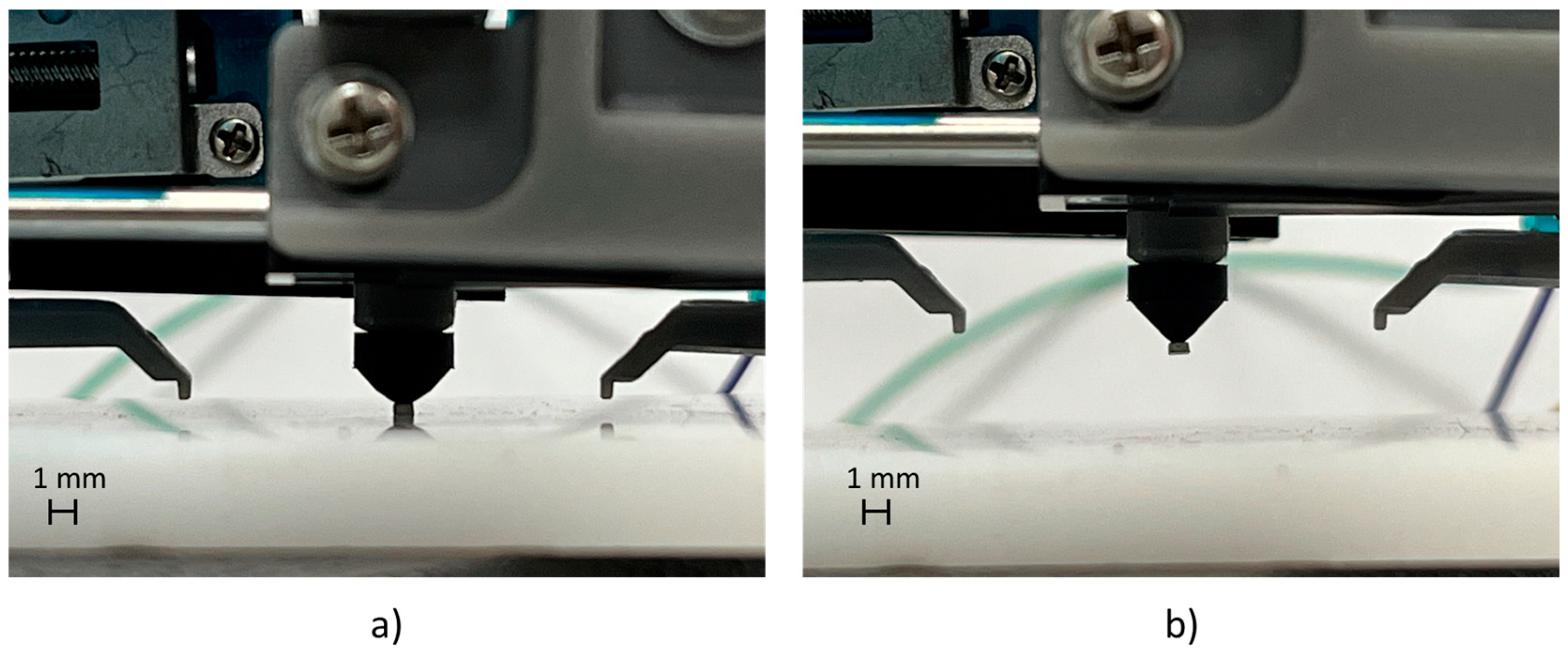
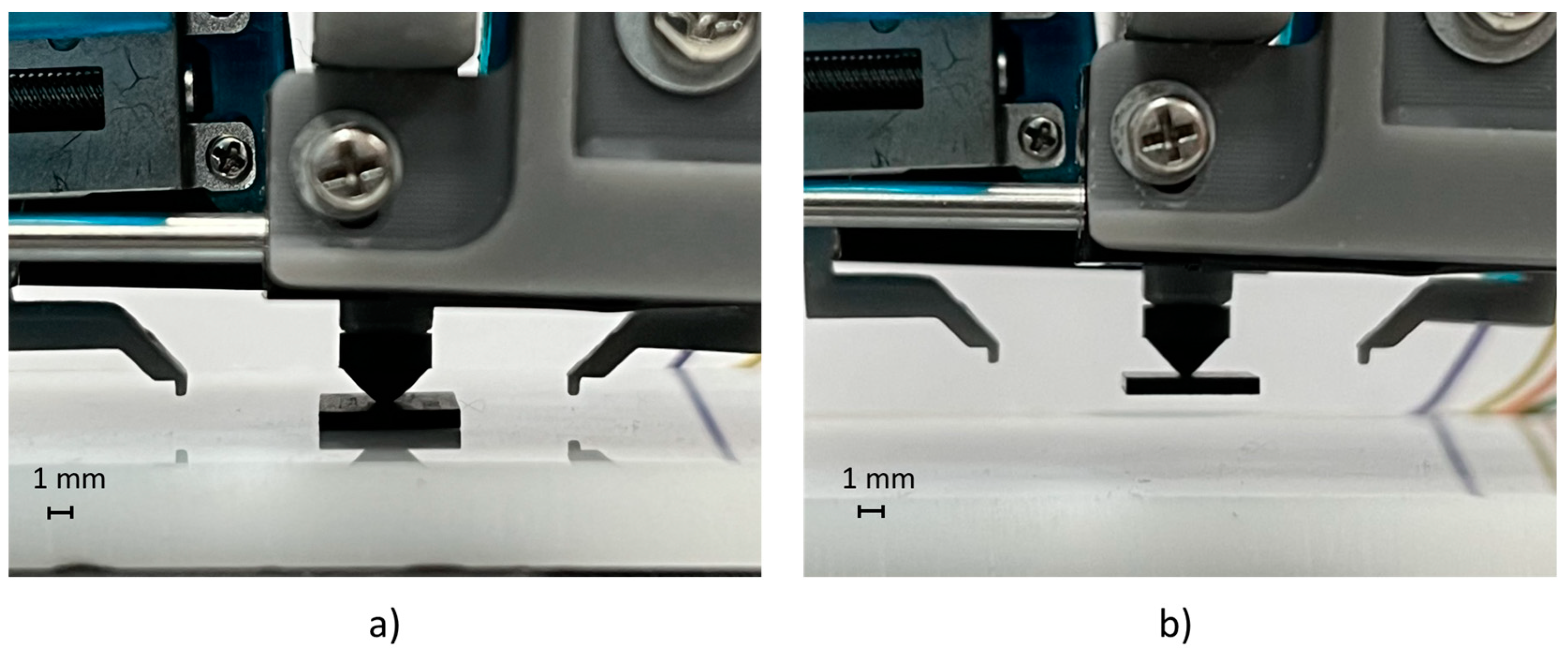
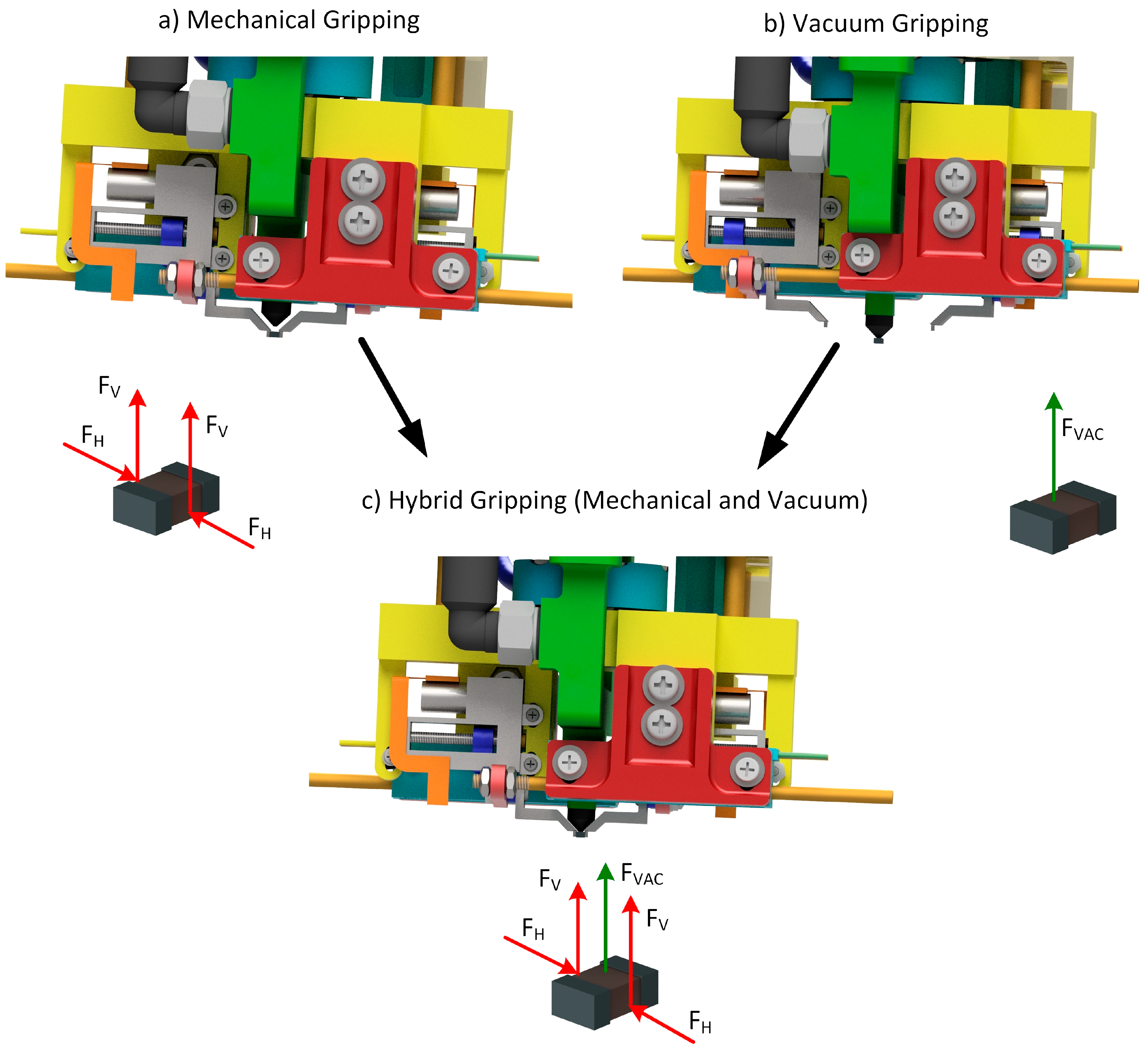
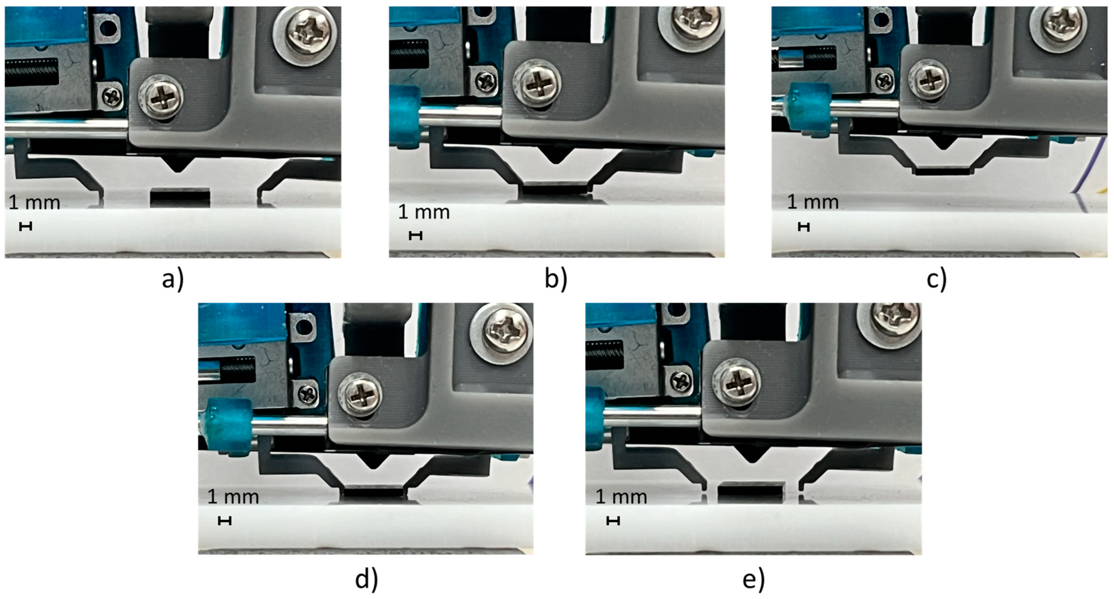
Finally, the hybrid manipulation mode combining mechanical and vacuum picking was tested by executing 30 cycles of pick-and-release operations.
Figure 19 shows the manipulation sequence of the BGA package with dimensions of 8 × 6 mm. The test result exploiting both picking technologies demonstrated that the designed gripper was able to manipulate SMT components in the dimensional range of 0.5–8 mm, with a reliability of 100%.


