
Power Amplifier Design for Ultrasound Applications


Abstract
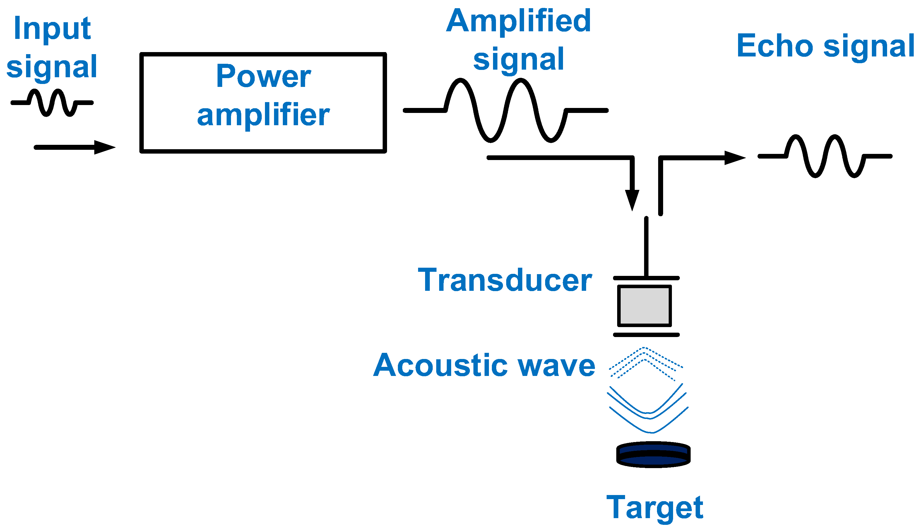
1. Introduction
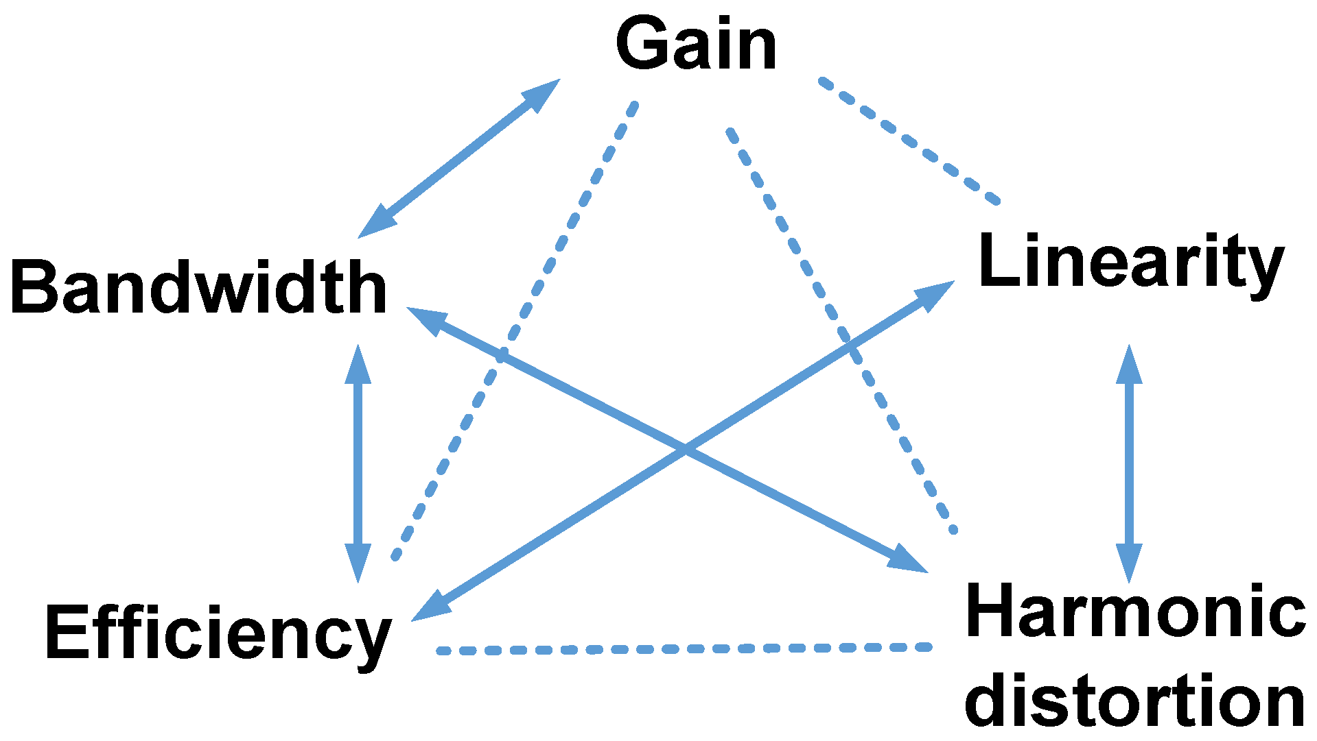
2. Design Parameters of Power Amplifiers
3. Classifications of Power Amplifiers
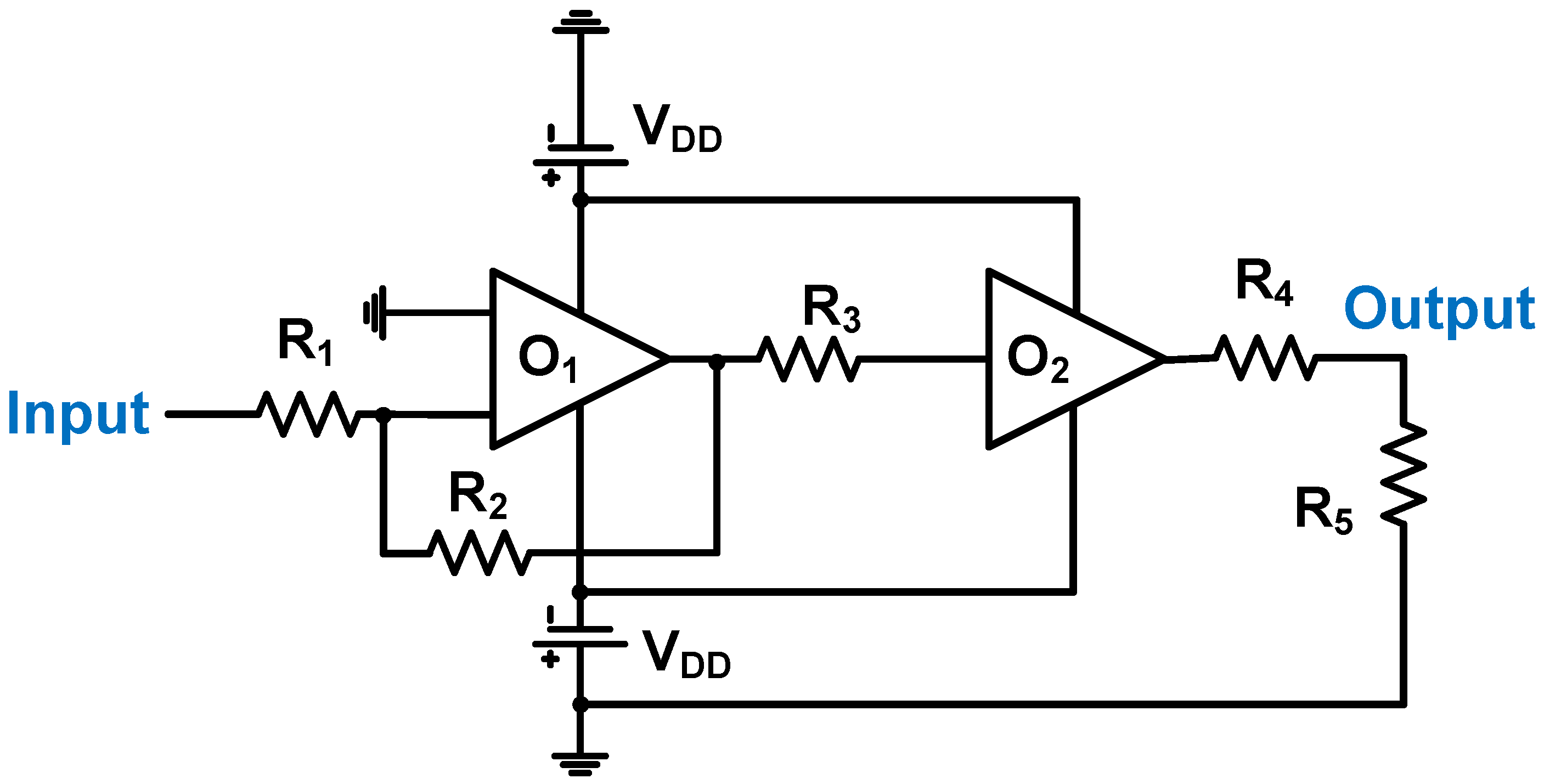
3.1. Class-A Power Amplifier
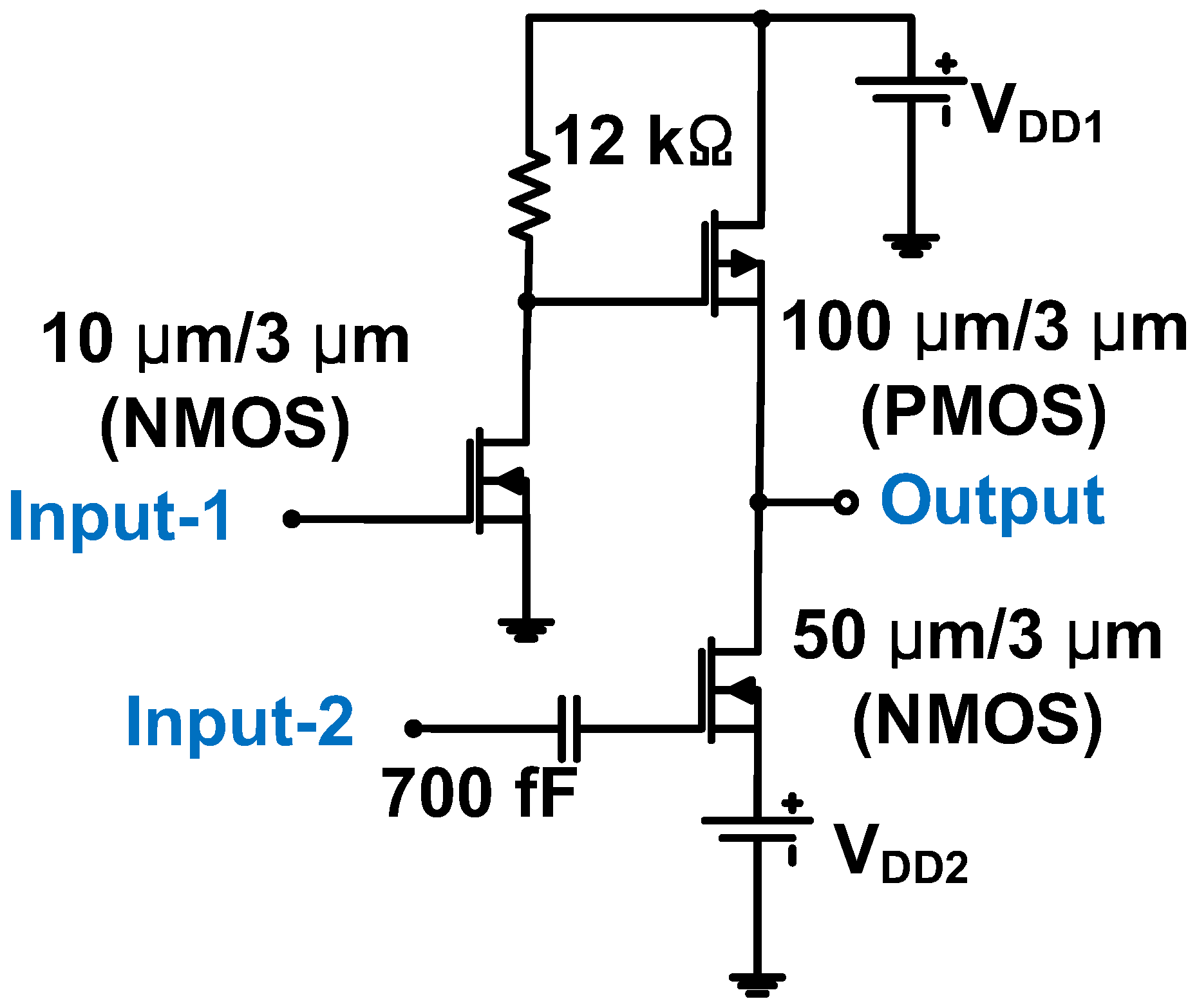
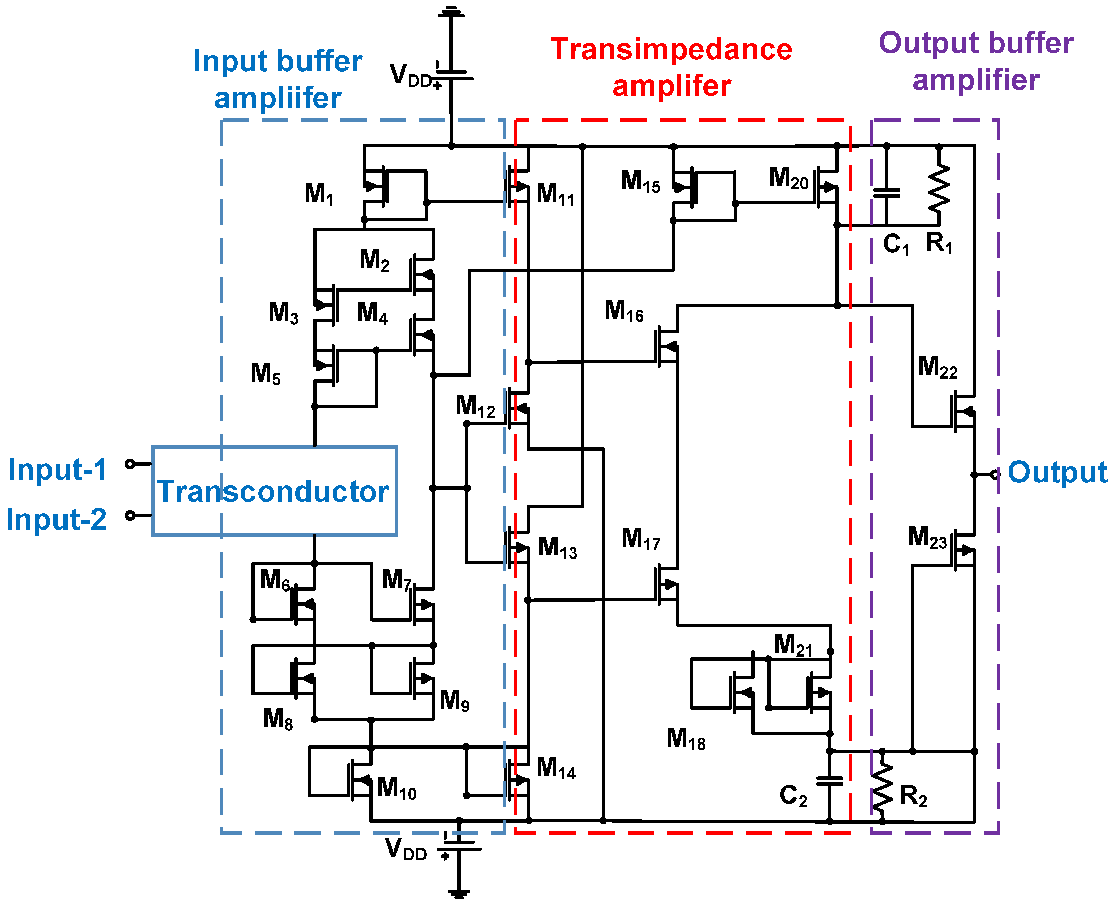
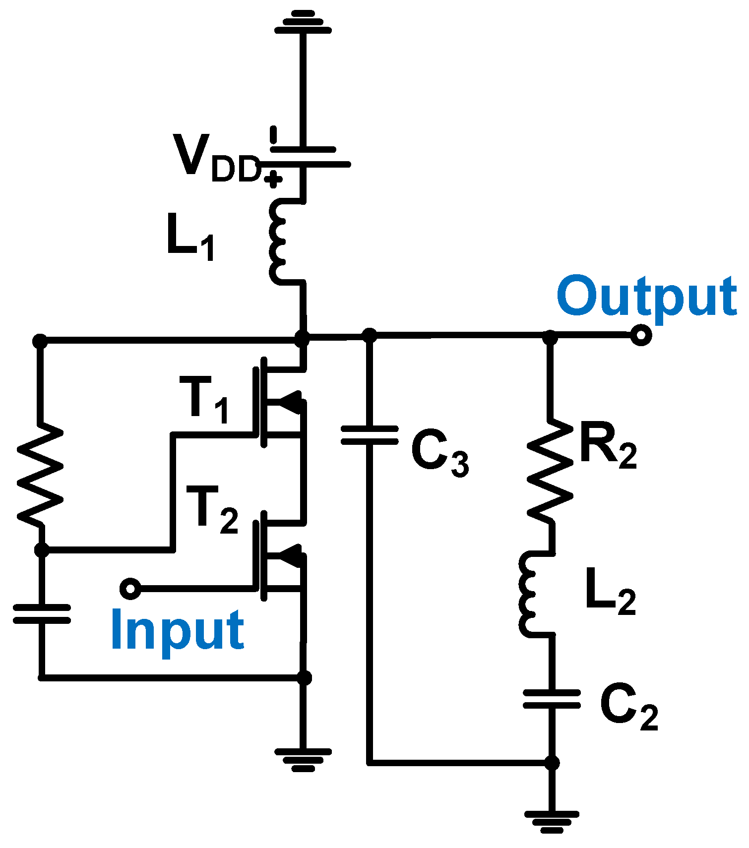
3.2. Class-B/AB Power Amplifier
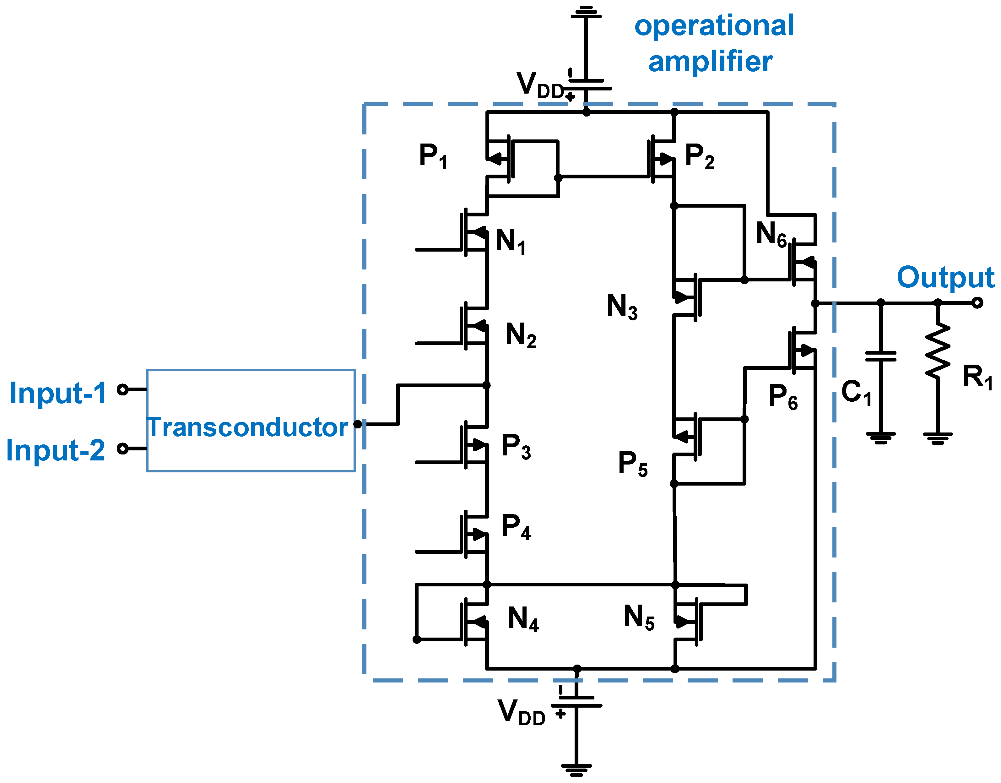
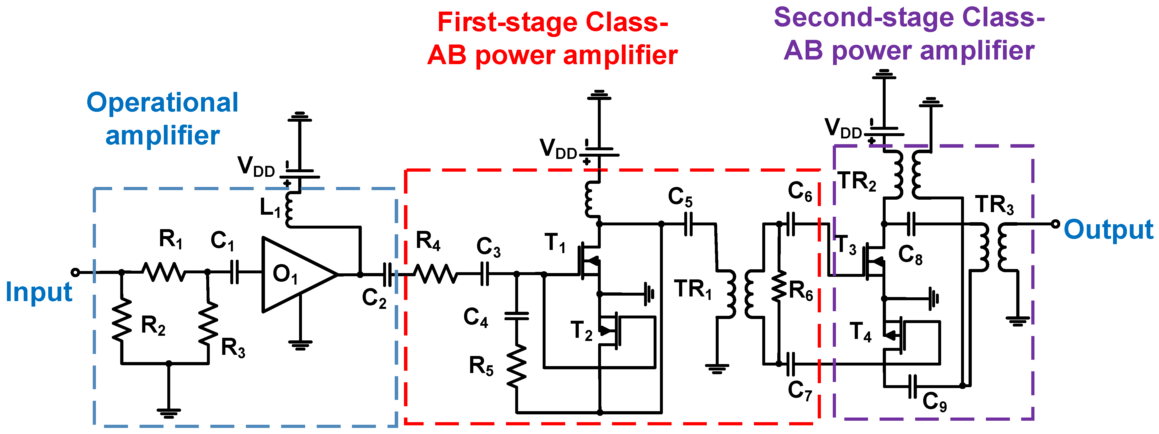
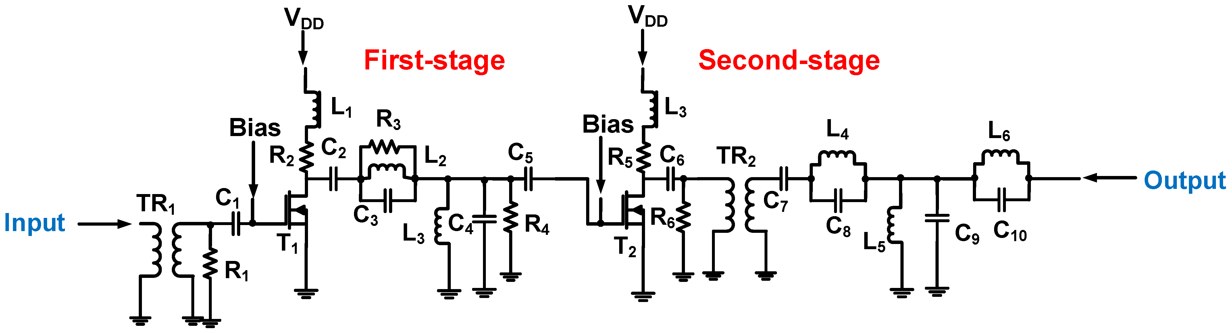
3.3. Class-C Power Amplifier
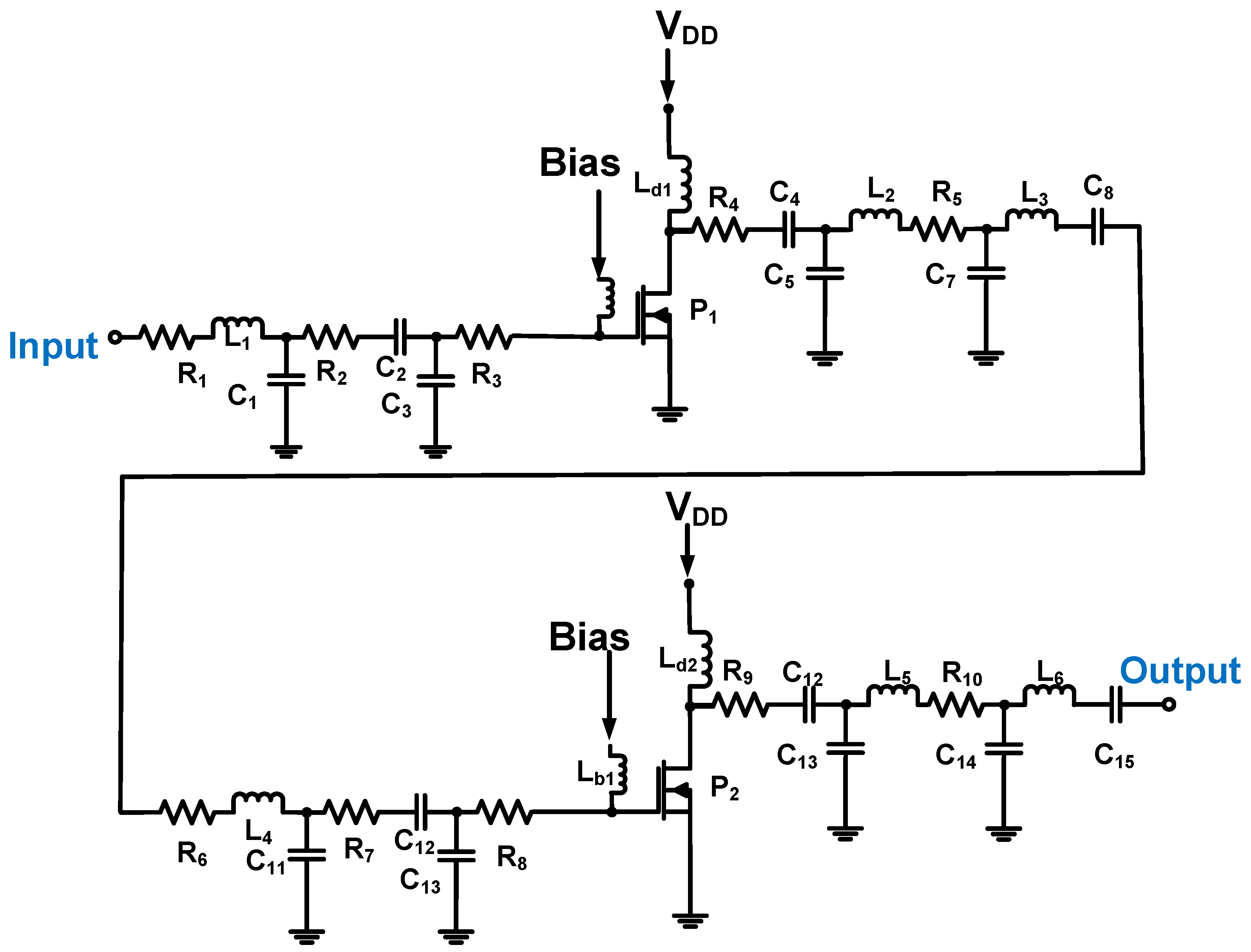
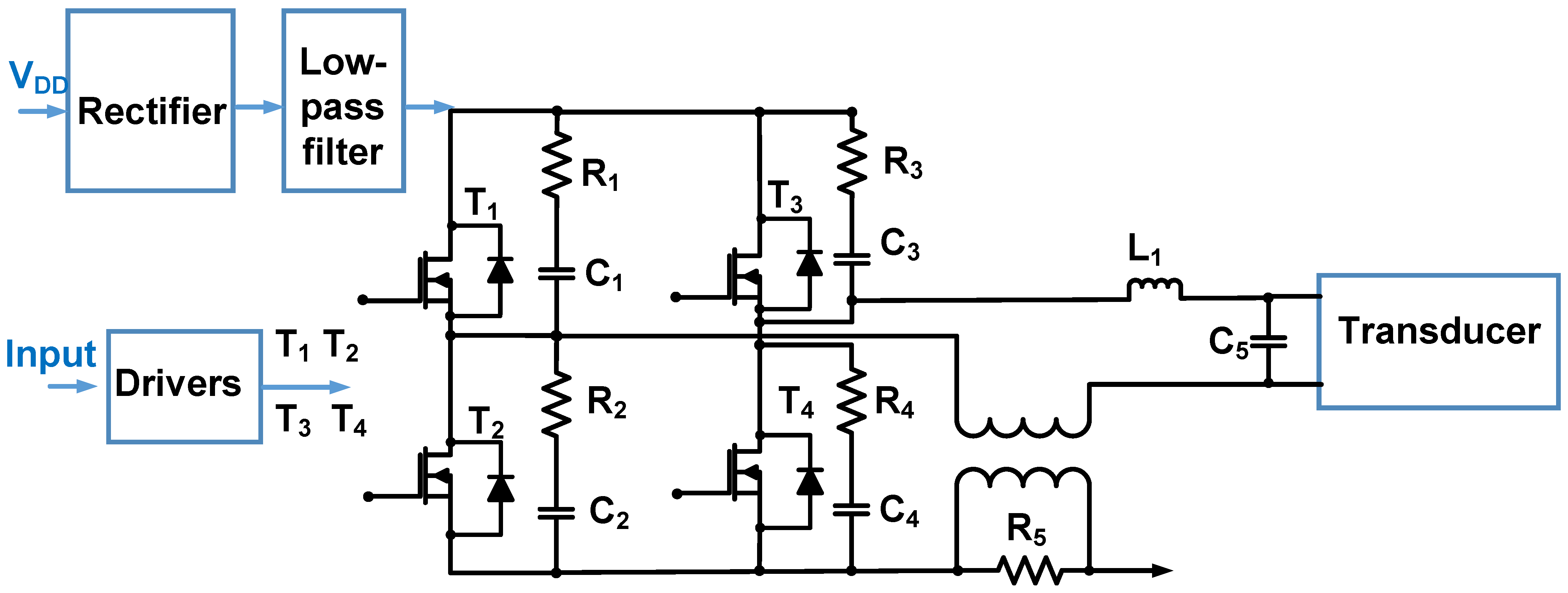
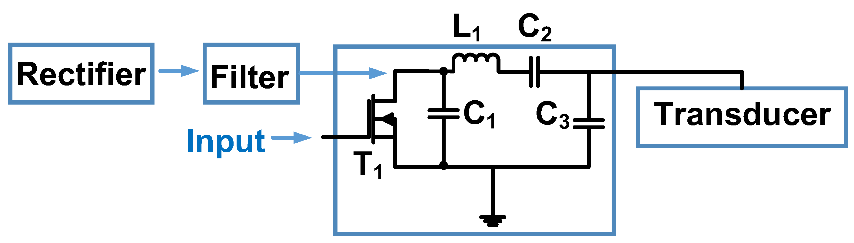
3.4. Class-D/DE Power Amplifier
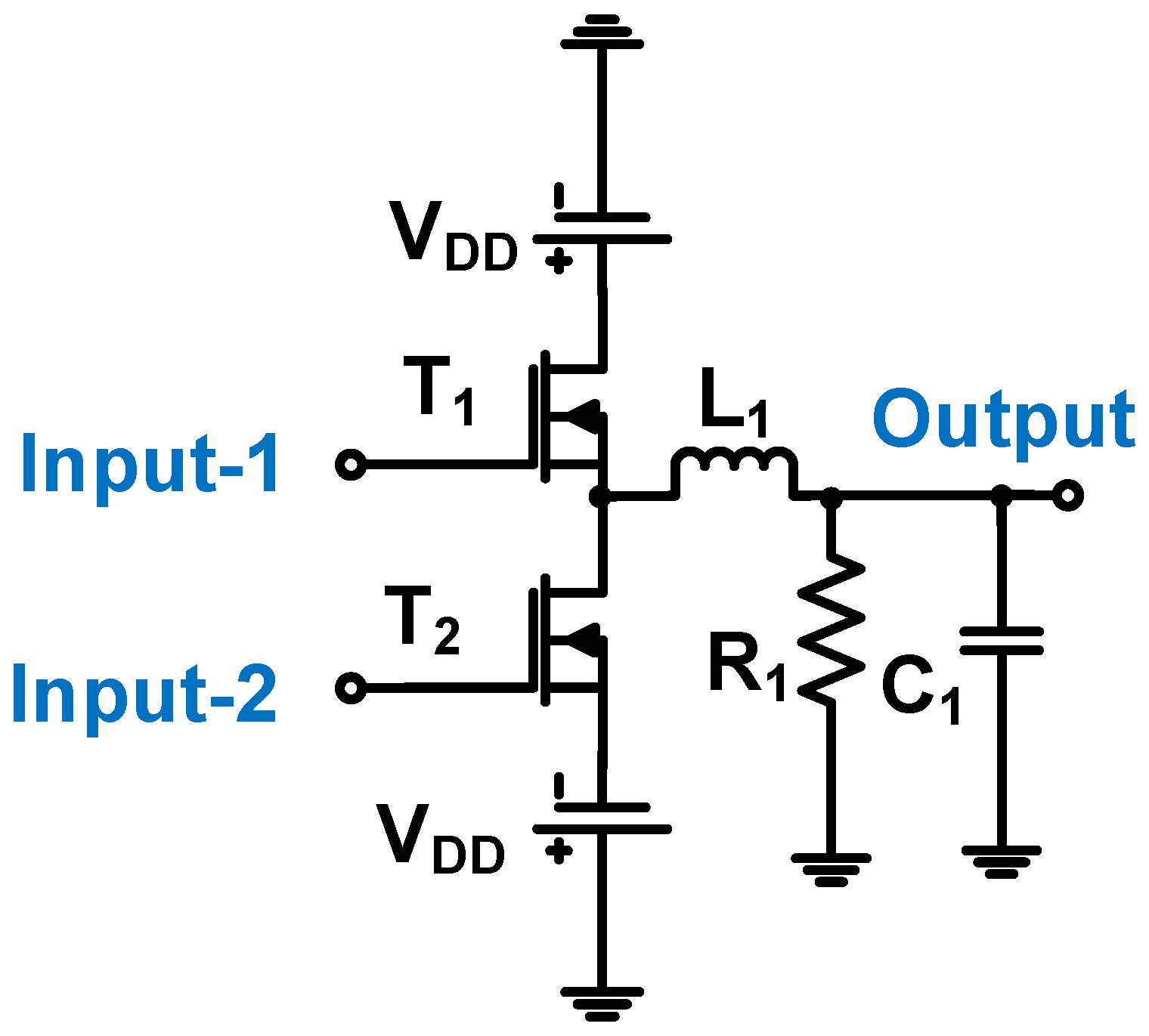
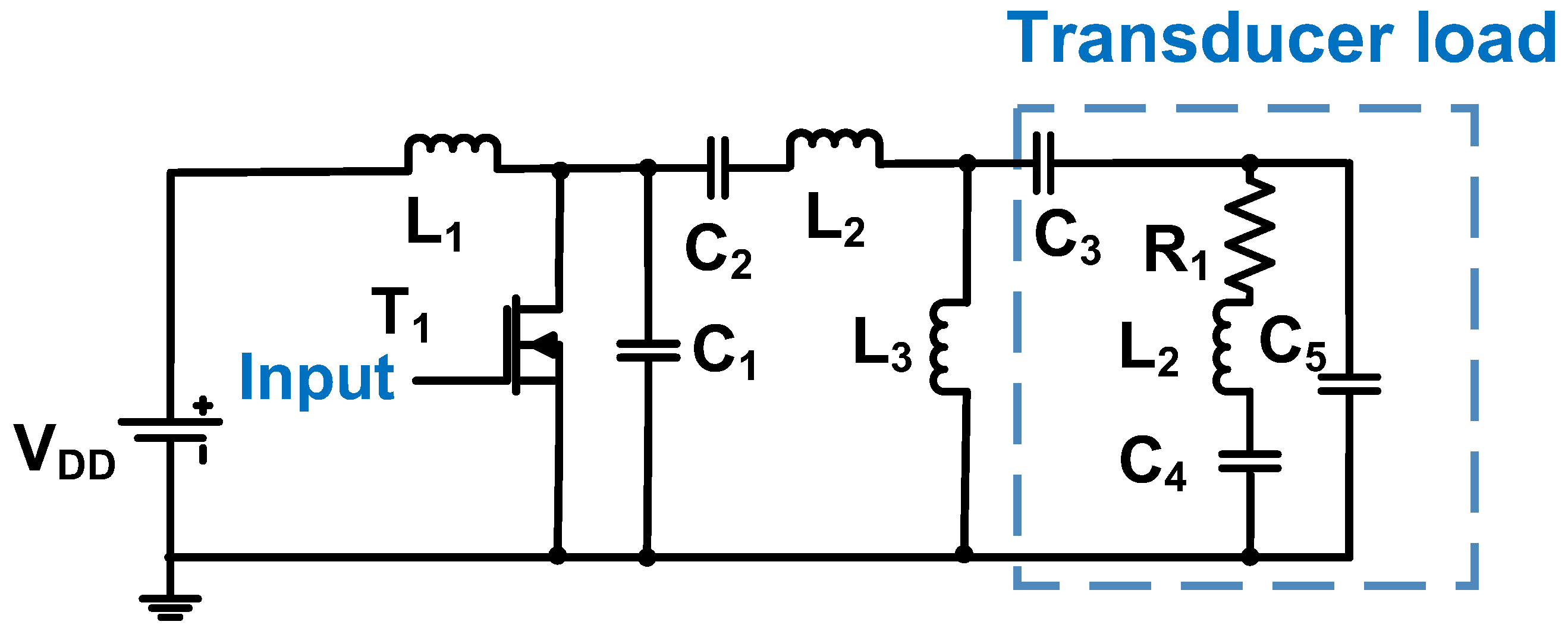
3.5. Class-E Power Amplifier
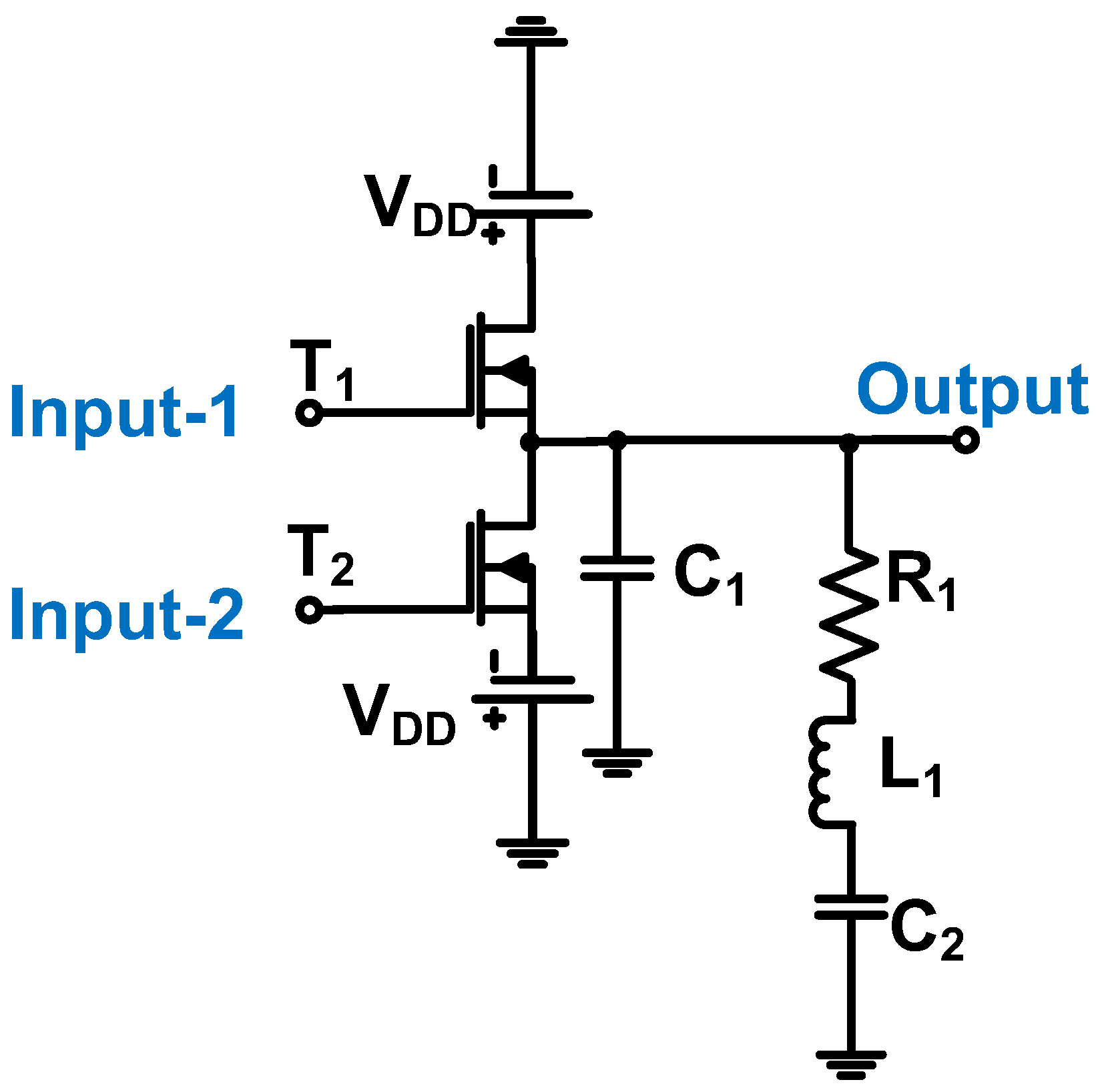
3.6. Class-F Power Amplifier
3.7. Power Amplifier Classification
4. Discussion
5. Conclusions
Funding
Data Availability Statement
Conflicts of Interest
Abbreviations
| DC | Direct current |
| AC | Alternating current |
| DAC | Digital-to-analog converter |
| MRI | Magnetic resonance imaging |
| PET | Positron emission tomography |
| HIFU | High-intensity focused ultrasound |
| CMUT | Capacitive micromachined ultrasonic transducer |
| HIM | Harmonic imaging method |
| IIP3 | Third input intercept point |
| OIP3 | Third output intercept point |
| PAE | Power added power efficiency |
| MOSFET | Metal-oxide-semiconductor field-effect transistor |
| HD2 | Second harmonic distortion |
| THD | Total harmonic distortion |
| LDMOS | Lateral diffusion metal-oxide semiconductor |
| DMOS | Double-diffused metal-oxide semiconductor |
| NMOS | N-channel MOS |
| PMOS | P-channel MOS |
References
- Hoff, L. Acoustic Characterization of Contrast Agents for Medical Ultrasound Imaging; Springer Science & Business Media: Berlin, Germany, 2001. [Google Scholar]
- Choi, H.; Ryu, J.-M.; Choe, S.-W. A novel therapeutic instrument using an ultrasound-light-emitting diode with an adjustable telephoto lens for suppression of tumor cell proliferation. Measurement 2019, 147, 106865. [Google Scholar] [CrossRef]
- Mason, T.J.; Peters, D. Practical Sonochemistry: Power Ultrasound Uses and Applications; Woodhead Publishing: Cambridge, UK, 2002. [Google Scholar]
- Saijo, Y.; Van Der Steen, A.F.W. Vascular Ultrasound; Springer Science & Business Media: Berlin, Germany, 2003. [Google Scholar]
- Choi, H. Development of negative-group-delay circuit for high-frequency ultrasonic transducer applications. Sens. Actuators A 2019, 299, 111616. [Google Scholar] [CrossRef]
- Jolesz, F.A.; Hynynen, K.H. MRI-Guided Focused Ultrasound Surgery; CRC Press: Boca Raton, FL, USA, 2007. [Google Scholar]
- Lisciandro, G.R. Focused Ultrasound Techniques for the Small Animal Practitioner; John Wiley & Sons: Hoboken, NJ, USA, 2014. [Google Scholar]
- Ullah, M.; Pratiwi, E.; Park, J.; Lee, K.; Choi, H.; Yeom, J. Wavelength discrimination (WLD) TOF-PET detector with DOI information. Phys. Med. Biol. 2019, 65, 055003. [Google Scholar] [CrossRef] [PubMed]
- Moore, C.L.; Copel, J.A. Point-of-care Ultrasonography. N. Engl. J. Med. 2011, 364, 749–757. [Google Scholar] [CrossRef] [PubMed]
- Karlen, W. Mobile Point-of-Care Monitors and Diagnostic Device Design; CRC Press: Boca Raton, FL, USA, 2014. [Google Scholar]
- Daniels, J.M.; Hoppmann, R.A. Practical Point-of-Care Medical Ultrasound; Springer: New York, NJ, USA, 2016. [Google Scholar]
- Baston, C.M.; Moore, C.; Dean, A.J.; Panebianco, N. Pocket Guide to POCUS: Point-of-Care Tips for Point-of-Care Ultrasound; McGraw Hill Education, Incorporated: New York, NJ, USA, 2019. [Google Scholar]
- Adhikari, S.; Blaivas, M. The Ultimate Guide to Point-of-Care Ultrasound-Guided Procedures; Springer: Berlin, Germany, 2019. [Google Scholar]
- Postema, M. Fundamentals of Medical Ultrasound; Taylor and Francis: New York, NJ, USA, 2011. [Google Scholar]
- Safari, A.; Akdogan, E.K. Piezoelectric and Acoustic Materials for Transducer Applications; Springer Science & Business Media: Berlin, Germany, 2008. [Google Scholar]
- Gibbs, V.; Cole, D.; Sassano, A. Ultrasound Physics and Technology: How, Why and When; Elsevier Health Sciences: Amsterdam, The Netherlands, 2011. [Google Scholar]
- Rozenberg, L.D. Sources of High-Intensity Ultrasound; Springer Science & Business Media: Berlin, Germany, 2013; Volume 1. [Google Scholar]
- Edelman, S.K. Understanding Ultrasound Physics; Baker & Taylor: Charlotte, NC, USA, 2012. [Google Scholar]
- Gallego-Juárez, J.A.; Graff, K.F. Power Ultrasonics: Applications of High-Intensity Ultrasound; Elsevier: Amsterdam, The Netherlands, 2014. [Google Scholar]
- Choi, H.; Li, X.; Lau, S.-T.; Hu, C.; Zhou, Q.; Shung, K.K. Development of Integrated Preamplifier for High-Frequency Ultrasonic Transducers and Low-Power Handheld Receiver. IEEE Trans. Ultrason. Ferroelectr. Freq. Control 2011, 58, 2646–2658. [Google Scholar] [CrossRef]
- Cannata, J.M.; Williams, J.A.; Zhou, Q.; Ritter, T.A.; Shung, K.K. Development of a 35-MHz piezo-composite ultrasound array for medical imaging. IEEE Trans. Ultrason. Ferroelectr. Freq. Control 2006, 53, 224–236. [Google Scholar] [CrossRef] [PubMed]
- Wu, D.-W.; Zhou, Q.; Geng, X.; Liu, C.-G.; Djuth, F.; Shung, K.K. Very high frequency (beyond 100 MHz) PZT kerfless linear arrays. IEEE Trans. Ultrason. Ferroelectr. Freq. Control 2009, 56, 2304–2310. [Google Scholar] [CrossRef]
- Hu, C.-H.; Xu, X.-C.; Cannata, J.M.; Yen, J.T.; Shung, K.K. Development of a real-time, high-frequency ultrasound digital beamformer for high-frequency linear array transducers. IEEE Trans. Ultrason. Ferroelectr. Freq. Control 2006, 53, 317–323. [Google Scholar]
- Suri, J.S.; Kathuria, C.; Chang, R.-F.; Molinar, F.; Fenster, A. Advances in Diagnostic and Therapeutic Ultrasound Imaging; Artech House: Norwood, MA, USA, 2008. [Google Scholar]
- Fry, F.J. Intense Focused Ultrasound in Medicine. Eur. Urol. 1993, 23 (Suppl. 1), 2–7. [Google Scholar] [CrossRef]
- Illing, R.O.; Kennedy, J.E.; Wu, F.; ter Haar, G.R.; Protheroe, A.S.; Friend, P.J.; Gleeson, F.V.; Cranston, D.W.; Phillips, R.R.; Middleton, M.R. The safety and feasibility of extracorporeal high-intensity focused ultrasound (HIFU) for the treatment of liver and kidney tumours in a Western population. Br. J. Cancer 2005, 93, 890–895. [Google Scholar] [CrossRef]
- Hrazdira, I.; Škorpíková, J.; Dolníková, M. Ultrasonically induced alterations of cultured tumour cells. Eur. J. Ultrasound 1998, 8, 43–49. [Google Scholar] [CrossRef] [PubMed]
- Yu, T.; Wang, Z.; Mason, T.J. A review of research into the uses of low level ultrasound in cancer therapy. Ultrason. Sonochem. 2004, 11, 95–103. [Google Scholar] [CrossRef] [PubMed]
- Tufail, Y.; Matyushov, A.; Baldwin, N.; Tauchmann, M.L.; Georges, J.; Yoshihiro, A.; Tillery, S.I.H.; Tyler, W.J. Transcranial pulsed ultrasound stimulates intact brain circuits. Neuron 2010, 66, 681–694. [Google Scholar] [CrossRef] [PubMed]
- Li, G.; Qiu, W.; Zhang, Z.; Jiang, Q.; Su, M.; Cai, R.; Li, Y.; Cai, F.; Deng, Z.; Xu, D. Noninvasive Ultrasonic Neuromodulation in Freely Moving Mice. IEEE Trans. Biomed. Eng. 2018, 2018, 217–224. [Google Scholar] [CrossRef]
- Lee, N.S.; Yoon, C.W.; Wang, Q.; Moon, S.; Koo, K.M.; Jung, H.; Chen, R.; Jiang, L.; Lu, G.; Fernandez, A. Focused ultrasound stimulates ER localized mechanosensitive PANNEXIN-1 to mediate intracellular calcium release in invasive cancer cells. Front. Cell Dev. Biol. 2020, 8, 504. [Google Scholar] [CrossRef]
- Qi, L.; Zhang, Q.; Tan, Y.; Lam, K.H.; Zheng, H.; Qian, M. Non-Contact High-Frequency Ultrasound Microbeam Stimulation: A Novel Finding and Potential Causes of Cell Responses. IEEE Trans. Biomed. Eng. 2020, 67, 1074–1082. [Google Scholar] [CrossRef]
- Jeong, J.J.; Choi, H. An impedance measurement system for piezoelectric array element transducers. Measurement 2017, 97, 138–144. [Google Scholar] [CrossRef]
- Lam, K.H.; Li, Y.; Li, Y.; Lim, H.G.; Zhou, Q.; Shung, K.K. Multifunctional single beam acoustic tweezer for non-invasive cell/organism manipulation and tissue imaging. Sci. Rep. 2016, 6, 37554. [Google Scholar] [CrossRef]
- Shung, K.K. Diagnostic Ultrasound: Imaging and Blood Flow Measurements; Taylor & Francis: Boca Raton, FL, USA, 2015. [Google Scholar]
- Zhu, B.; Han, J.; Shi, J.; Shung, K.K.; Wei, Q.; Huang, Y.; Kosec, M.; Zhou, Q. Lift-off PMN-PT Thick Film for High Frequency Ultrasonic Biomicroscopy. J. Am. Ceram. Soc. 2010, 93, 2929–2931. [Google Scholar] [CrossRef]
- Szabo, T.L. Diagnostic Ultrasound Imaging: Inside Out; Elsevier Academic Press: London, UK, 2013. [Google Scholar]
- Khan, M.; Khan, T.M. Tunable Q matching networks for capacitive ultrasound transmitters. Analog Integr. Circuits Signal Process. 2022, 111, 301–312. [Google Scholar] [CrossRef]
- Khuri-Yakub, B.T.; Oralkan, Ö.; Nikoozadeh, A.; Wygant, I.O.; Zhuang, S.; Gencel, M.; Choe, J.W.; Stephens, D.N.; de la Rama, A.; Chen, P.; et al. Miniaturized Ultrasound Imaging Probes Enabled by CMUT Arrays with Integrated Frontend Electronic Circuits. IEEE Eng. Med. Biol. 2010, 1, 5987–5990. [Google Scholar]
- Lee, T.H. The Design of CMOS Radio-Frequency Integrated Circuits; Cambridge University Press: Cambridge, UK, 2006. [Google Scholar]
- Albulet, M. RF Power Amplifiers; SciTech Publishing: London, UK, 2001. [Google Scholar]
- Zhang, X.; Larson, L.E.; Asbeck, P. Design of Linear RF Outphasing Power Amplifiers; Artech House: Norwood, MA, USA, 2003. [Google Scholar]
- Grebennikov, A. RF and Microwave Power Amplifier Design; McGraw-Hill: New York, NJ, USA, 2005. [Google Scholar]
- Cripps, S.C. RF Power Amplifiers for Wireless Communications; Artech House: Norwood, MA, USA, 2006. [Google Scholar]
- Klaassen, F.; De Graaff, H. Compact Transistor Modelling for Circuit Design; Springer: Berlin, Germany, 1990. [Google Scholar]
- Gonzalez, G. Microwave Transistor Amplifiers: Analysis and Design; Prentice Hall: New Jersey, NJ, USA, 1997. [Google Scholar]
- Ritchie, G.J. Transistor Circuit Techniques: Discrete and Integrated; CRC Press: Boca Raton, FL, USA, 2003. [Google Scholar]
- Wilamowski, B.M.; Irwin, J.D. Fundamentals of Industrial Electronics; CRC Press: Boca Raton, FL, USA, 2018. [Google Scholar]
- Duan, Z.; Fan, T.; Wen, X.; Zhang, D. Improved SiC Power MOSFET Model Considering Nonlinear Junction Capacitances. IEEE Trans. Power Electron. 2018, 33, 2509–2517. [Google Scholar] [CrossRef]
- Chen, W.-K. High Performance Analog Circuits. In The Circuits and Filters Handbook; CRC Press: Boca Raton, FL, USA, 2002. [Google Scholar]
- Carr, J. RF Components and Circuits; Elsevier: Amsterdam, The Netherlands, 2002. [Google Scholar]
- Aarts, A.C.T.; Kloosterman, W.J. Compact modeling of high-voltage LDMOS devices including quasi-saturation. IEEE Trans. Electron Devices 2006, 53, 897–902. [Google Scholar] [CrossRef]
- Irwin, J.D.; Wu, C.-H. Basic Engineering Circuit Analysis; Wiley: New York, NJ, USA, 1999. [Google Scholar]
- Erlbacher, T. Lateral Power Transistors in Integrated Circuits; Springer: Berlin, Germany, 2014. [Google Scholar]
- Reynaert, P.; Steyaert, M. RF Power Amplifiers for Mobile Communications; Springer Science & Business Media: Berlin, Germany, 2006. [Google Scholar]
- Hella, M.M.; Ismail, M. RF CMOS Power Amplifiers: Theory, Design and Implementation; Springer Science & Business Media: Berlin, Germany, 2006. [Google Scholar]
- Qiu, W.; Wang, X.; Chen, Y.; Fu, Q.; Su, M.; Zhang, L.; Xia, J.; Dai, J.; Zhang, Y.; Zheng, H. A Modulated Excitation Imaging System for Intravascular Ultrasound. IEEE Trans. Biomed. Eng. 2016, 64, 1935–1942. [Google Scholar] [CrossRef] [PubMed]
- Soni, N.J.; Arntfield, R.; Kory, P. Point of Care Ultrasound; Elsevier Health Sciences: Oxford, UK, 2014. [Google Scholar]
- Lumb, P. Critical Care Ultrasound; Elsevier Health Sciences: Oxford, UK, 2014. [Google Scholar]
- Wagner, P.R.; Hedrick, W.R. Point-of-Care Ultrasound Fundamentals: Principles, Devices, and Patient Safety; McGraw Hill Professional: New York, NJ, USA, 2014. [Google Scholar]
- Golio, J.; Golio, M. RF and Microwave Circuits, Measurements, and Modeling; CRC Press: Boca Raton, FL, USA, 2007. [Google Scholar]
- Miele, F.R. Ultrasound Physics & Instrumentation; Pegasus Lectures, Inc.: Forney, TX, USA, 2013. [Google Scholar]
- Raghavan, A.; Srirattana, N.; Laskar, J. Modeling and Design Techniques for RF Power Amplifiers; John Wiley & Sons: Hoboken, NJ, USA, 2008. [Google Scholar]
- Sechi, F.; Bujatti, M. Solid-State Microwave High-Power Amplifiers; Artech House: Norwood, MA, USA, 2009. [Google Scholar]
- Dawson, J.L.; Lee, T.H. Feedback Linearization of RF Power Amplifiers; Springer Science & Business Media: Berlin, Germany, 2007. [Google Scholar]
- Chang, K. Microwave Solid-State Circuits and Applications; Wiley: New York, NJ, USA, 1994. [Google Scholar]
- Kenington, P.B. High Linearity RF Amplifier Design; Artech House, Inc.: Norwood, MA, USA, 2000. [Google Scholar]
- Steer, M. Microwave and RF Design; NC State University: Raleigh, NC, USA, 2019. [Google Scholar]
- Choi, H. An Inverse Class-E Power Amplifier for Ultrasound Transducer. Sensors 2023, 23, 3466. [Google Scholar] [CrossRef] [PubMed]
- Walker, J.L. Handbook of RF and Microwave Power Amplifiers; Cambridge University Press: Cambridge, UK, 2011. [Google Scholar]
- Choi, H.; Yoon, C.; Yeom, J.-Y. A Wideband High-Voltage Power Amplifier Post-Linearizer for Medical Ultrasound Transducers. Appl. Sci. 2017, 7, 354. [Google Scholar] [CrossRef]
- Razavi, B. Fundamentals of Microelectronics; Wiley: Hoboken, NJ, USA, 2008. [Google Scholar]
- Ciçek, I.; Bozkurt, A.; Karaman, M. Design of a front-end integrated circuit for 3D acoustic imaging using 2D CMUT arrays. IEEE Trans. Ultrason. Ferroelectr. Freq. Control 2005, 52, 2235–2241. [Google Scholar] [CrossRef]
- Kazimierczuk, M.K. RF Power Amplifier; John Wiley & Sons: Hoboken, NJ, USA, 2014. [Google Scholar]
- Grebennikov, A.; Sokal, N.O.; Franco, M.J. Switchmode RF Power Amplifiers; Newnes: Amsterdam, The Netherlands, 2011. [Google Scholar]
- Eroglu, A. Introduction to RF Power Amplifier Design and Simulation; CRC Press: Boca Raton, FL, USA, 2018. [Google Scholar]
- Herbst, L.J. Integrated Circuit Engineering: Establishing a Foundation; Oxford University Press: Oxford, UK, 1996. [Google Scholar]
- Razavi, B. Design of Analog CMOS Integrated Circuits; McGraw-Hill Science: New York, NJ, USA, 2016. [Google Scholar]
- Bianchi, D.; Quaglia, F.; Mazzanti, A.; Svelto, F. Analysis and Design of a High Voltage Integrated Class-B Amplifier for Ultra-Sound Transducers. IEEE Trans. Circuits Syst. I Regul. Pap. 2014, 61, 1942–1951. [Google Scholar] [CrossRef]
- Capineri, L. A 15 MHz bandwidth, 60 Vpp, low distortion power amplifier for driving high power piezoelectric transducers. Rev. Sci. Instrum. 2014, 85, 104701. [Google Scholar] [CrossRef]
- Gao, Z.; Gui, P.; Jordanger, R. An integrated high-voltage low-distortion current-feedback linear power amplifier for ultrasound transmitters using digital predistortion and dynamic current biasing techniques. IEEE Trans. Circuits Syst. II Express Briefs 2014, 61, 373–377. [Google Scholar] [CrossRef]
- Yeo, K.S.; Do, M.A.; Boon, C.C. Design of CMOS RF Integrated Circuits and Systems; World Scientific: London, UK, 2010. [Google Scholar]
- Chen, W.-K. Analog Circuits and Devices; CRC Press: Boca Raton, FL, USA, 2003. [Google Scholar]
- Ghisu, D.; Gambero, A.; Terenzi, M.; Ricotti, G.; Moroni, A.; Rossi, S. 180 Vpp output voltage, 24 MHz bandwidth, low power class AB current-feedback high voltage amplifier for ultrasound transmitters. In Proceedings of the 2018 IEEE Custom Integrated Circuits Conference (CICC), San Diego, CA, USA, 8–11 April 2018; pp. 1–4. [Google Scholar]
- Qiu, W.; Zhou, J.; Chen, Y.; Su, M.; Li, G.; Zhao, H.; Gu, X.; Meng, D.; Wang, C.; Xiao, Y.; et al. A Portable Ultrasound System for Non-Invasive Ultrasonic Neuro-Stimulation. IEEE Trans. Neural Syst. Rehabil. Eng. 2017, 25, 2509–2515. [Google Scholar] [CrossRef]
- Narayanaswami, R.S. RF CMOS Class C Power Amplifiers for Wireless Communications; University of California: Berkeley, CA, USA, 2001. [Google Scholar]
- Vuolevi, J.; Rahkonen, T. Distortion in RF Power Amplifiers; Artech House: London, UK, 2003. [Google Scholar]
- Cripps, S.C. Advanced Techniques in RF Power Amplifier Design; Artech House: Norwood, MA, USA, 2002. [Google Scholar]
- Choi, H. Class-C Linearized Amplifier for Portable Ultrasound Instruments. Sensors 2019, 19, 898. [Google Scholar] [CrossRef] [PubMed]
- Sjoland, H. Highly Linear Integrated Wideband Amplifiers: Design and Analysis Techniques for Frequencies from Audio to RF; Springer Science & Business Media: Berlin, Germany, 1999. [Google Scholar]
- Self, D. Audio Power Amplifier Design; Focal Press: Waltham, MA, USA, 2013. [Google Scholar]
- Dal Fabbro, P.A.; Kayal, M. Linear CMOS RF Power Amplifiers for Wireless Applications: Efficiency Enhancement and Frequency-Tunable Capability; Springer Science & Business Media: Berlin, Germany, 2010. [Google Scholar]
- Agbossou, K.; Dion, J.-L.; Carignan, S.; Abdelkrim, M.; Cheriti, A. Class D Amplifier for a Power Piezoelectric Load. IEEE Trans. Ultrason. Ferroelectr. Freq. Control 2000, 47, 1036–1041. [Google Scholar] [CrossRef] [PubMed]
- Nielsen, D.; Knott, A.; Andersen, M.A.E. A high-voltage class D audio amplifier for dielectric elastomer transducers. In Proceedings of the 2014 IEEE Applied Power Electronics Conference and Exposition—APEC 2014, Fort Worth, TX, USA, 16–20 March 2014; pp. 3278–3283. [Google Scholar]
- Christoffersen, C.; Wong, W.; Pichardo, S.; Togtema, G.; Curiel, L. Class-DE ultrasound transducer driver for HIFU therapy. IEEE Trans. Biomed. Circuits Syst. 2016, 10, 375–382. [Google Scholar] [CrossRef]
- Yuan, T.; Dong, X.; Shekhani, H.; Li, C.; Maida, Y.; Tou, T.; Uchino, K. Driving an inductive piezoelectric transducer with class E inverter. Sens. Actuators A 2017, 261 (Suppl. C), 219–227. [Google Scholar] [CrossRef]
- Allen, P.E.; Holberg, D.R. CMOS Analog Circuit Design; Oxford University Press: Oxford, UK, 2002. [Google Scholar]
- Tu, S.H.-L.; Tsai, P.-Y. A Class-E high-voltage pulse generator for ultrasound medical imaging applications. Microelectron. J. 2020, 100, 104776. [Google Scholar] [CrossRef]
- Niyomthai, S.; Sangswang, A.; Naetiladdanon, S.; Mujjalinvimut, E. Operation region of class E resonant inverter for ultrasonic transducer. In Proceedings of the 2017 14th International Conference on Electrical Engineering/Electronics, Computer, Telecommunications and Information Technology (ECTI-CON), Phuket, Thailand, 27–30 June 2017; pp. 435–438. [Google Scholar]
- Kim, K.; Choi, H. High-efficiency high-voltage class F amplifier for high-frequency wireless ultrasound systems. PLoS ONE 2021, 16, e0249034. [Google Scholar] [CrossRef]
- Choi, H. A Doherty Power Amplifier for Ultrasound Instrumentation. Sensors 2023, 23, 2406. [Google Scholar] [CrossRef]


| Paper | Class Mode | Operating or Center Frequency | Output Power | Output Voltage | −3 dB Bandwidth | Gain | Harmonic Distortion or THD | Efficiency or PAE | Application |
|---|---|---|---|---|---|---|---|---|---|
| [71] | Class-A | 10 MHz | 14.21 dBm | - | - | 15.6 dB | - | - | Piezoelectric Transducer |
| [73] | Class-A | 2 MHz | - | 15 V | - | - | - | - | CMUT |
| [79] | Class-B | - | - | - | 6.5 MHz | 40.9 dB | <−35 dB (HD2) | - | Ultrasonic Transducer |
| [80] | Class-AB | - | 3.09 W | 27.25 V | 15 MHz | - | - | 5.66% | Ultrasonic Transducer |
| [81] | Class-AB | - | - | 180 V | 8.6 MHz | - | −48 dB | - | Piezoelectric Transducer |
| [84] | Class-AB | - | - | 180 V | 22 MHz | - | −48 dB | - | Medical Echography |
| [85] | Class-AB | 5 MHz | - | 48 V | - | 40 dB | - | - | Neuromodulation |
| [89] | Class-C | 25 MHz | - | - | - | 17.14 dB | - | - | Piezoelectric Transducer |
| [93] | Class-D | 100 kHz | 2000 W | - | - | - | - | - | Power Piezoelectric Load |
| [94] | Class-D | 0.1 kHz | - | - | 43.5 dB | - | 42% | Dielectric Elastomer Transducer | |
| [95] | Class-DE | 1010 kHz | 0.83 W | - | - | - | −16.4 dB (HD2) | - | HIFU Therapy |
| [96] | Class-E | 40.07 kHz | 0.219 W | - | - | - | - | - | Langevin Piezoelectric Transducer |
| [98] | Class-E | 32 MHz | - | 36.5 V | - | - | - | - | CMUT |
| [99] | Class-E | 28.11 kHz | - | 112 V | - | - | - | - | Piezoelectric Transducer |
| [100] | Class-F | 25 MHz | 33.5 dBm | - | - | 23.5 dB | 5.0% | 78.8% | Piezoelectric Transducer |
| Class Mode | Contribution | Limitation |
|---|---|---|
| Class-A | Highly linear characteristics and thus preferable for ultrasound imaging applications. | Because it has low efficiency, it could not be recommended for a wireless ultrasound machine. |
| Class-AB/B | The positive and negative DC supply makes a high gain achievable. | A combinational logic circuit and stable DAC circuit are necessary. |
| Class-C | Low DC power consumption can be obtained. | A delicate biasing circuit topology is necessary. |
| Class-D/DE | High power efficiency can be obtained. The modulated pulse signals can be generated by a user-defined function. | Because of the high signal distortion, high-order low-pass filters and complex combinational logic circuits are required. |
| Class-E | Output matching circuit equations can provide the proper component values for the power amplifier. | A fine-tuning method is needed to achieve an appropriate current and voltage phase condition. |
| Class-F | High efficiency can be obtained. | A delicate harmonic distortion filter is required. |
Disclaimer/Publisher’s Note: The statements, opinions and data contained in all publications are solely those of the individual author(s) and contributor(s) and not of MDPI and/or the editor(s). MDPI and/or the editor(s) disclaim responsibility for any injury to people or property resulting from any ideas, methods, instructions or products referred to in the content. |
© 2023 by the author. Licensee MDPI, Basel, Switzerland. This article is an open access article distributed under the terms and conditions of the Creative Commons Attribution (CC BY) license (https://creativecommons.org/licenses/by/4.0/).
Share and Cite
Choi, H. Power Amplifier Design for Ultrasound Applications. Micromachines 2023, 14, 1342. https://doi.org/10.3390/mi14071342
Choi H. Power Amplifier Design for Ultrasound Applications. Micromachines. 2023; 14(7):1342. https://doi.org/10.3390/mi14071342
Chicago/Turabian StyleChoi, Hojong. 2023. "Power Amplifier Design for Ultrasound Applications" Micromachines 14, no. 7: 1342. https://doi.org/10.3390/mi14071342
APA StyleChoi, H. (2023). Power Amplifier Design for Ultrasound Applications. Micromachines, 14(7), 1342. https://doi.org/10.3390/mi14071342