Article

RC Bridge Oscillation Memristor Chaotic Circuit for Electrical and Electronic Technology Extended Simulation Experiment

1
The College of Electrical Engineering and Automation, Shandong University of Science and Technology, Qingdao 266590, China
2
Faculty of Science and Engineering, University of Nottingham Ningbo China, Ningbo 315100, China
*
Author to whom correspondence should be addressed.
Micromachines 2023, 14(2), 410; https://doi.org/10.3390/mi14020410
Submission received: 2 January 2023 / Revised: 29 January 2023 / Accepted: 5 February 2023 / Published: 9 February 2023

Abstract

:
The fourth basic circuit component, the memristor, has been proposed for a long time, but it is not mentioned in the experiment teaching system of Electrical and Electronic Technology. In this paper, an RC bridge oscillation chaotic circuit based on memristor is designed to solve this problem. The dynamical behavior of the circuit system is analyzed using Lyapunov exponents spectrum, bifurcation diagram, phase portrait and Poincaré map. A series of complex dynamical behaviors such as symmetric single-scroll coexistence, asymmetrical single-scroll coexistence, symmetric double-scroll coexistence and asymmetrical limit–cycle coexistence exist in the circuit system. This research plays a critical role in enriching students’ knowledge and improving the experiment teaching system of Electrical and Electronic Technology.

1. Introduction

In 1971, Chua predicted the existence of the memristor as the fourth circuit elements except resistance, inductance, and capacitance [1]. In 2008, researchers at Hewlett-Packard Labs developed the first physical memristor element, which drew academic attention to memristors [2]. In 2011, Torrezan and Strachan et al. tested a metal-tantalum oxide-metal structured memristor integrated in an experimental device with a 20 GHz bandwidth, and found that it had sub-second switching characteristics [3]. In 2020, Kim et al. found that a memristor based on a quasi-two-dimensional structure of chalcogenide material as a semiconductor dielectric has a more desirable switching ratio and stability [4]. In 2021, Almadhoun et al. developed a bipolar memristor that can maintain a resistive on/off state for up to 10 5 s [5]. With the development of neural networks [6,7,8], memristor has become one of the important ways to realize neural network circuits [9,10]. Due to its ability to hysterically change its resistance in response to previously applied electrical stimuli [11,12], the memristor has attracted considerable interest in various hypothetical applications, such as nonvolatile memories [13,14], logic gates [15,16,17], hybrid logic/memory circuits [18,19,20], and neuromorphic computing [21,22,23,24,25]. In addition, the unique features of this device have stimulated interest in generating nonlinear and chaotic dynamics [26,27]. In recent years, the research and application on chaotic systems have become more and more abundant [28,29,30,31]. By introducing memristors with different nonlinearities into existing circuits, a large number of circuits based on memristor have been proposed and very fruitful results have been obtained [32,33,34,35,36,37,38]. For example, complex dynamic behaviors have been discovered in various memristor-based circuits, including multistability [39], transient chaos [40], and hyperchaos [41]. Although the research of memristor is more and more abundant now, there are few applications in the experimental teaching system of Electrical and Electronic Technology. This experiment aims to enrich students’ experience and improve their ability to adapt to society [42]. Therefore, it is necessary to apply memristor to teaching systems.
Most of the memristors used in current chaotic circuits are implemented by analog circuit and FPGA [43]. In the paper, a flux-controlled mathematical model of physical SBT memristor is used [44,45]. In this work, the physical memristor is used and the program design is simplified to adapt to the experimental teaching. This experiment is implemented by simulation, in order to analyze its dynamic behavior conveniently. An RC bridge oscillation chaotic circuit based on physical memristor is proposed, and its dynamic behaviors, especially the coexistence of multi-dynamics, are analyzed by means of Lyapunov exponents spectrum bifurcation diagram and phase portraits.
The rest of the paper is organized as follows: Section 2 presents the mathematical model of flux control of physical memristor and RC bridge chaotic circuit, and the equation of state for the circuit was established by the voltage–current relationship of circuit elements and Kirchhoff’s circuit law. Section 3 analyzes the stability of the equilibrium point, the influence of the initial state and circuit parameters on the system dynamics through the Lyapunov exponents spectrum, and the bifurcation diagram. Section 4 focuses on the effect of flux change on the circuit. Finally, the conclusions are given in Section 5.

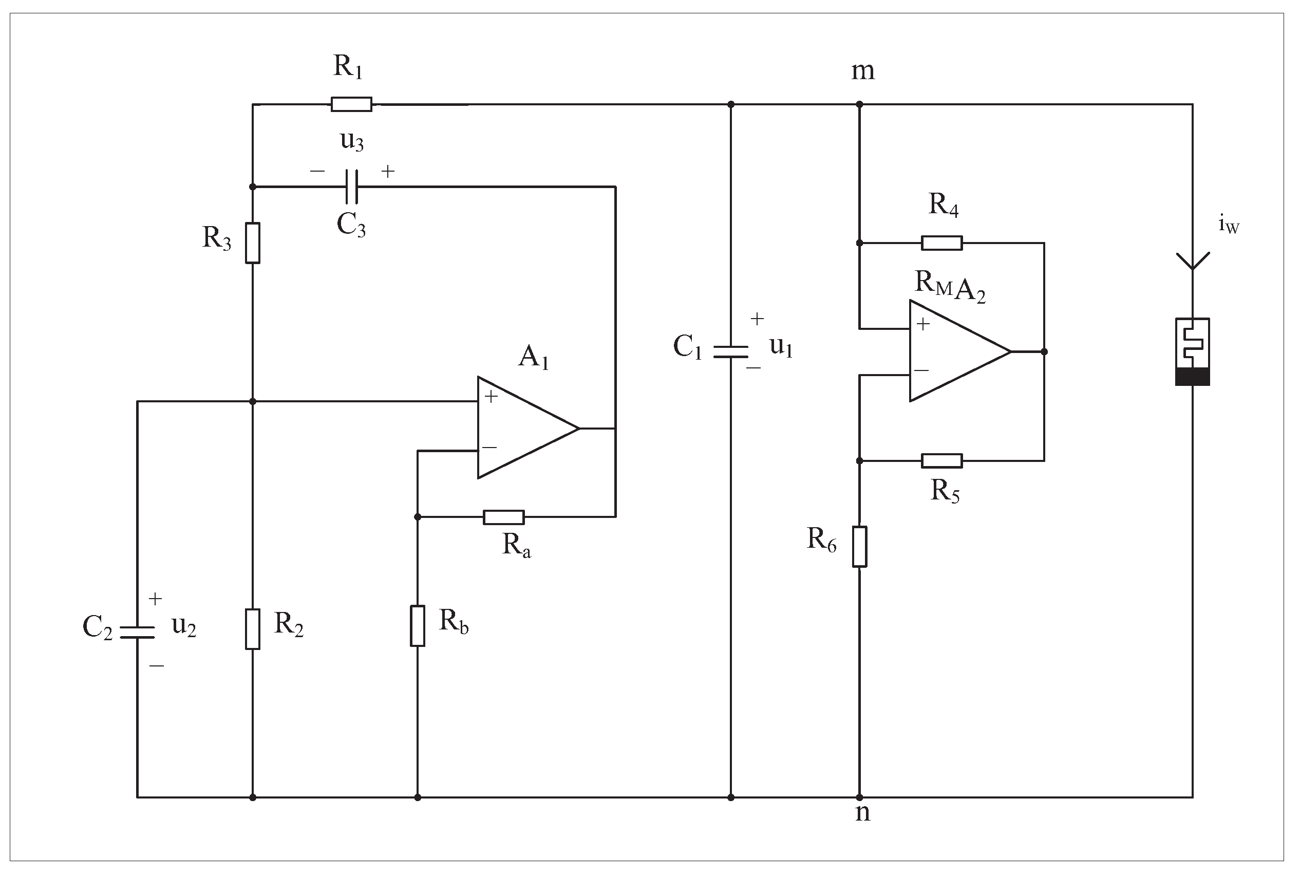
2. Chaotic Circuit Based on Quadratic Smooth Model of Memristor

In our previous work, we prepared the SBT memristor [44]. As a new circuit element, memristor represents the connection between charge and flux. A quadratic smoothing model is applied in this paper to describe this connection [45].
q = f φ φ + g φ + h
u t = d φ t d t i t = d q t d t
W φ t = d q t d φ t
W φ t = j + k φ t
where φ t and q t represent magnetic flux and charge, respectively, and i t and u t represent the current flowing through the memristor and the voltage at both ends.
A chaotic circuit including a second-order RC bridge oscillator, capacitor, negative resistor and SBT memristor is constructed as shown in Figure 1. The RC oscillating bridge circuit can generate sinusoidal waves with adjustable frequency, which lays out the condition for the subsequent test. Coupling capacitors can connect the front and rear circuits. Negative resistance can play a controlling role. The existence of memristors is one of the conditions of chaos. Setting R 2 = R 3 , C 2 = C 3 and amplification A u of op-amp A 1 is as follows:
A u = 1 + R a R b
The second-order RC bridge oscillator satisfies the oscillation condition. The oscillation circuit is coupled with the memristor through C 1 . In previous studies, the mathematical model of the memristor had been proposed [45], and the quadratic smooth model of the memristor was obtained based on experimental measurements. The model of the memristor is as follows:
W 2 φ t = A + B φ t d φ t d t = u t
where A = 0.03 S , B = 0.0614 S / W b , the current i W flowing through the SBT memristor is expressed as:
i W = u 1 · W φ t
The equivalent negative resistance R m n between nodes m and n is:
R m n = R 4 R 6 R 5
The equation of state for the circuit shown in Figure 1 is:
d u 1 t d t = 1 C 1 A u 2 u 3 u 1 R 1 u 1 R m n u 1 · W φ t d u 2 t d t = 1 C 2 A 1 u 2 u 3 R 3 u 2 R 2 d u 3 t d t = 1 C 3 A u 2 u 1 u 3 R 1 + A 1 u 2 u 3 R 3 d φ t d t = u 1
The four state variables u 1 t , u 2 t , u 3 t , φ t in Equation (2) correspond to the voltage of the capacitor C 1 , the voltage of the capacitor C 2 , the voltage of the capacitor C 3 and the internal flux of the SBT memristor. Setting τ = t C 2 R 2 , x = u 1 E , y = u 2 E , z = u 3 E , ω = φ C 2 R 2 E , R 2 = R 3 , C 2 = C 3 , E = 1 V , C 2 R 2 = 1 s , the dimensionless dynamical system Equation (3) is obtained as follows:
d x d τ = a b A y z x c x x · W ω d y d τ = A 2 y z d z d τ = b A y x z + A 1 y z d ω d τ = x
where a = C 2 C 1 , b = R 2 R 1 , c = R 2 R m n , W ω = 0.03 + 0.0614 ω .
When setting the initial states as (0.01, 0, 0, 0), a = 40 , b = 0.15 , c = 0.2 , A u = 3.2 , the numerical simulation yields four Lyapunov exponents as L E 1 = 0.0123 , L E 2 = 0.0027 , L E 3 = 0.0350 , and L E 4 = 3.03 , which indicate that the system is chaotic.
The three-dimensional and two-dimensional phase portraits of chaotic circuit system are shown in Figure 2 and Figure 3, respectively. The circuit system shows a double-scroll attractor phenomenon at this time.
The Poincaré maps on the two cross-sections y = 0 and x = 0 are in Figure 4, and the trajectory of the circuit system has a complex folding phenomenon.
Figure 5a shows the spectrum of Lyapunov exponents of the system in the time interval 0 , 3000 , where the fourth negative Lyapunov exponent is omitted for the convenience of observation. The maximum Lyapunov exponents are always positive, and the sum of all the Lyapunov exponents is always negative, which represents that the system has chaotic attractors. In Figure 5b, the time domain waveforms with respect to the state variables x and w are non-periodic irregular oscillations. In summary, it can be judged that the circuit system (Figure 1) has chaotic oscillation, and it is proved that the quadratic smooth model based on the SBT memristor can be used to construct chaotic circuits.

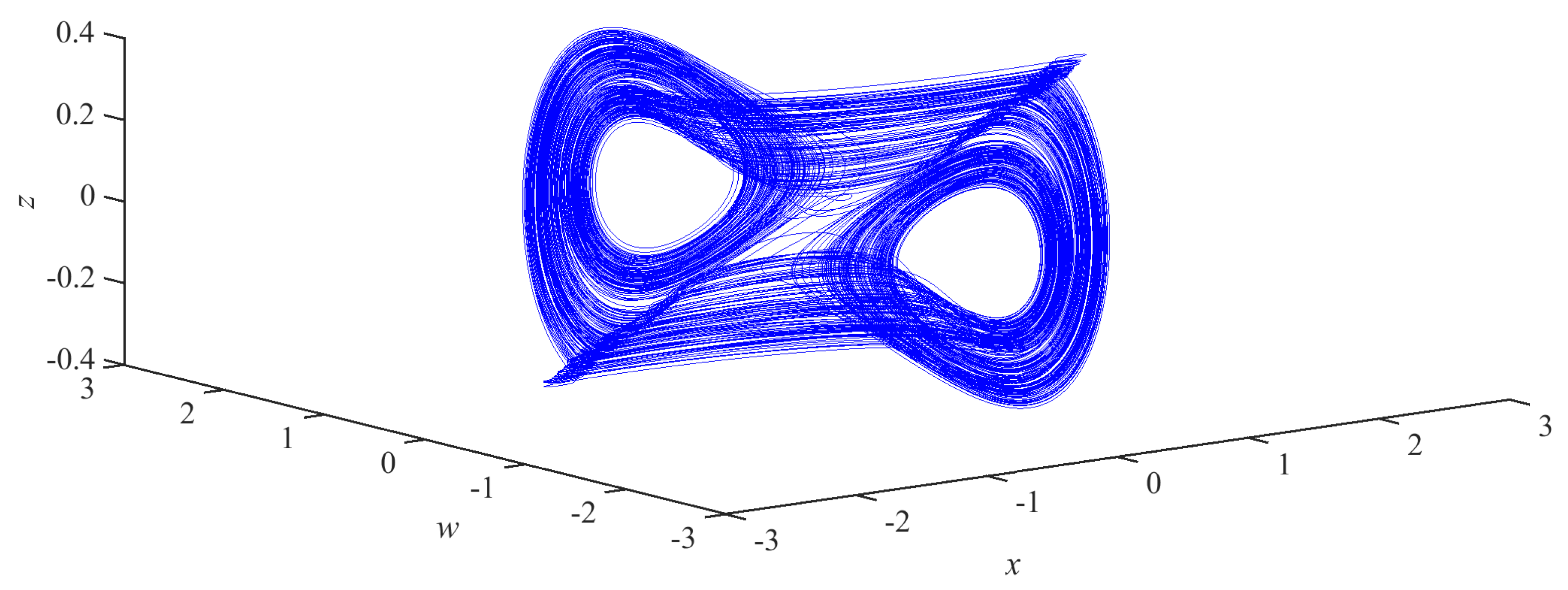
3. Dynamical Behavior of Chaotic System

3.1. Equilibrium Point and Stability Analysis

In Equation (3):
d x d τ = 0 , d y d τ = 0 , d z d τ = 0 , d w d τ = 0
the set of equilibrium points of this system can be obtained as:
E = x , y , z , w x = y = z = 0 , w = φ 0
where φ 0 is an arbitrary constant, and the Jacobi matrix of the system is:
J = a b + c + W 2 a b A a b 0 0 A 2 1 0 b b A + A + 1 b 1 0 1 0 0 0
The eigenvalue equation of the system Jacobi matrix is as follows:
λ I J = λ λ 3 + A 2 λ 2 + A 1 λ + A 0 = 0
In Equation (4), W 2 = 0.03 + 0.0614 φ 0 , the system parameters a = 40 , b = 0.15 , c = 0.2 , A u = 3.2 , and the three coefficients of the characteristic equation are obtained:
A 2 = 2.456 φ 0 0.85 A 1 = 0.1228 φ 0 + 0.44 A 0 = 3.1928 φ 0 2.84
Referring to the Routh–Hurwitz stability criterion, the sufficient condition that all the characteristic roots of this circuit system have negative real parts is obtained as:
H k = A 0 A 2 0 1 A 1 0 0 A 0 A 2 > 0
where k = 1 , 2 , 3 , then:
H 1 = A 2 > 0 H 2 = A 0 > 0 H 3 = A 2 A 1 A 0 > 0
From Equation (5), the stability interval of the circuit system corresponding to φ 0 is a null set, so the system is always unstable.

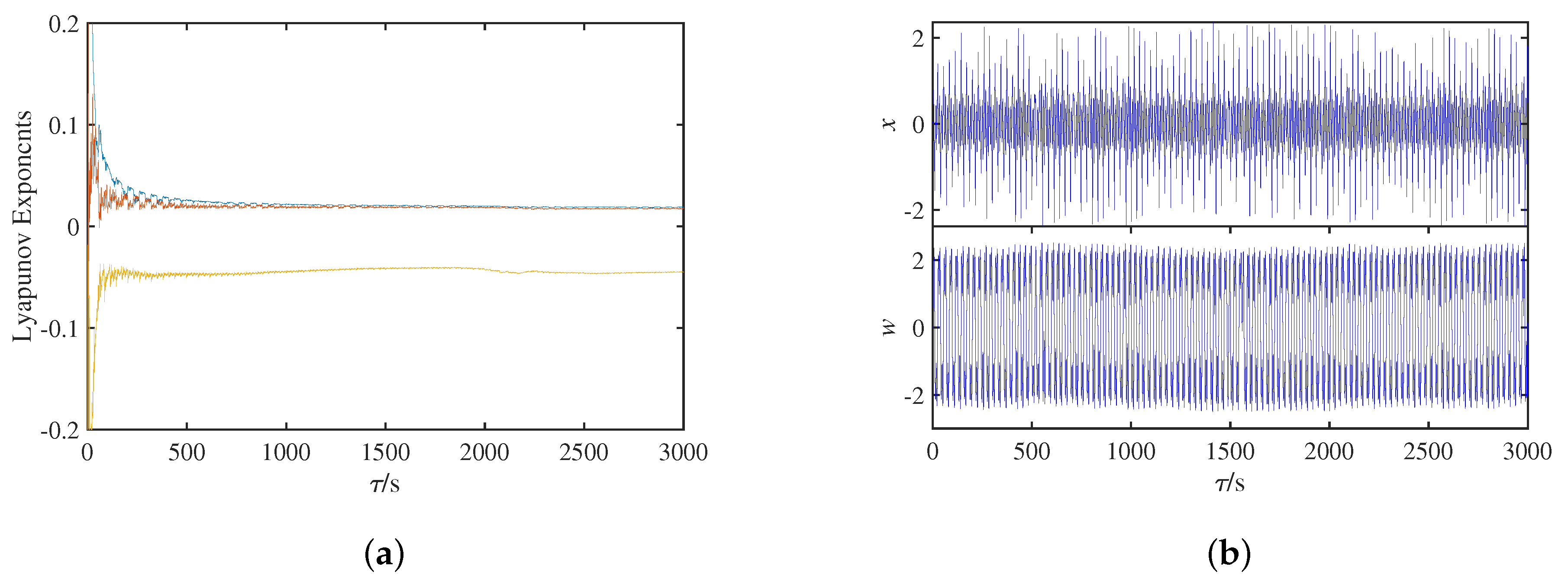
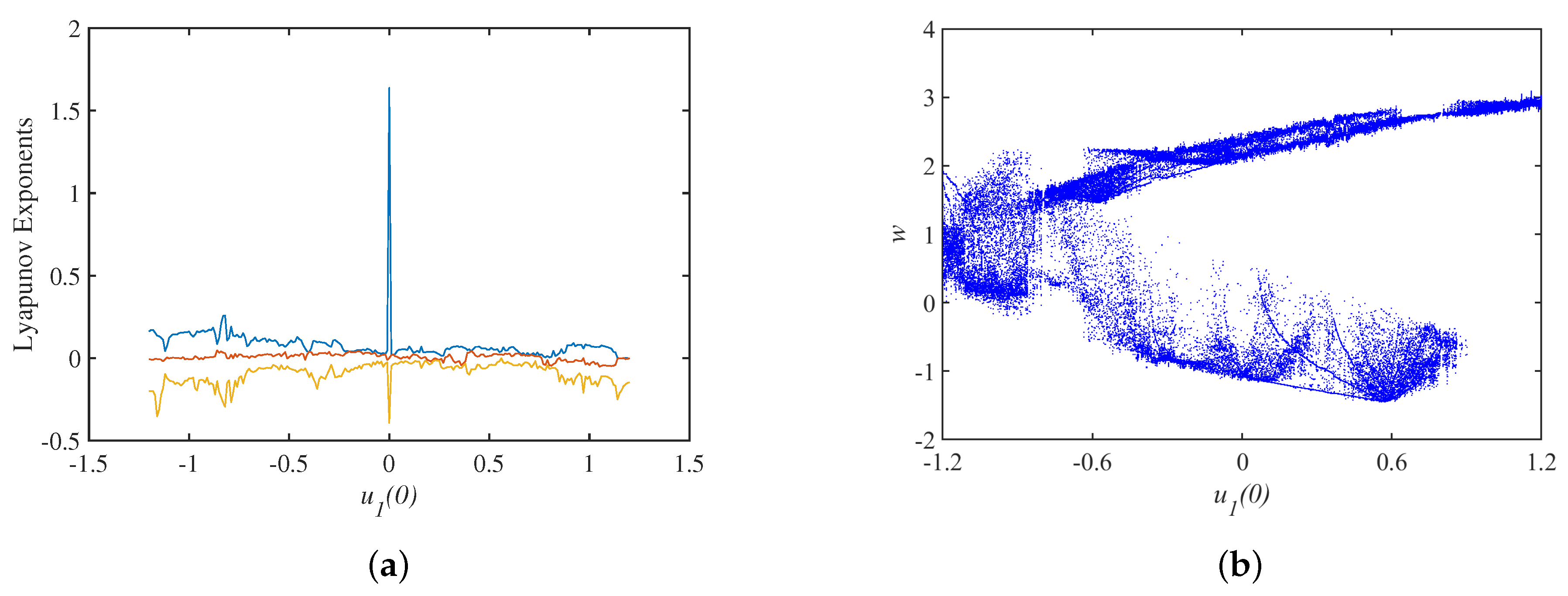
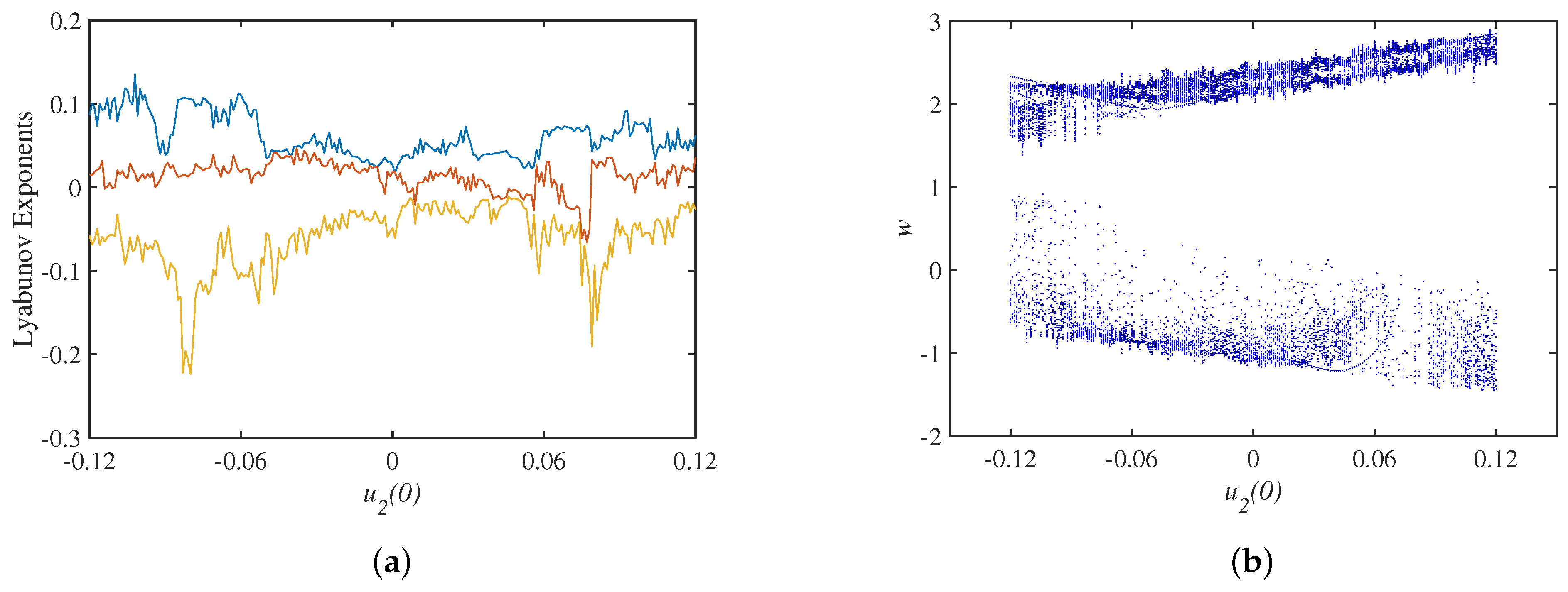
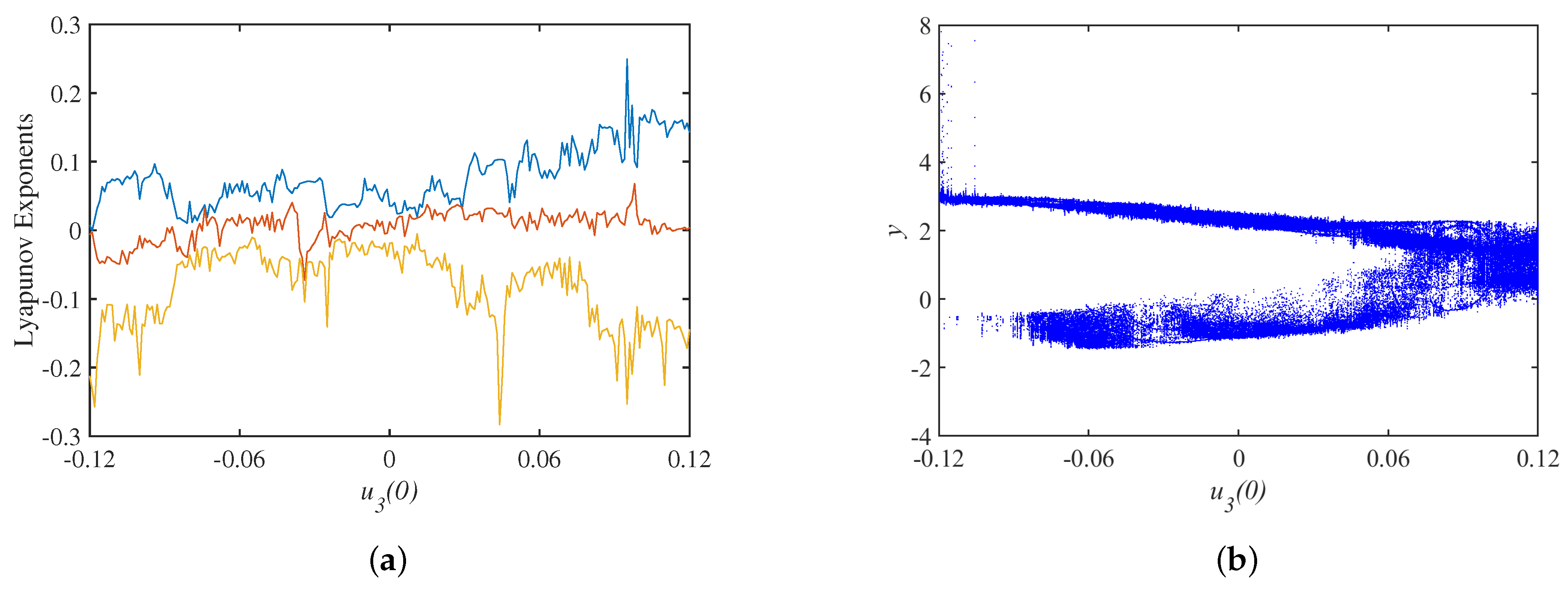
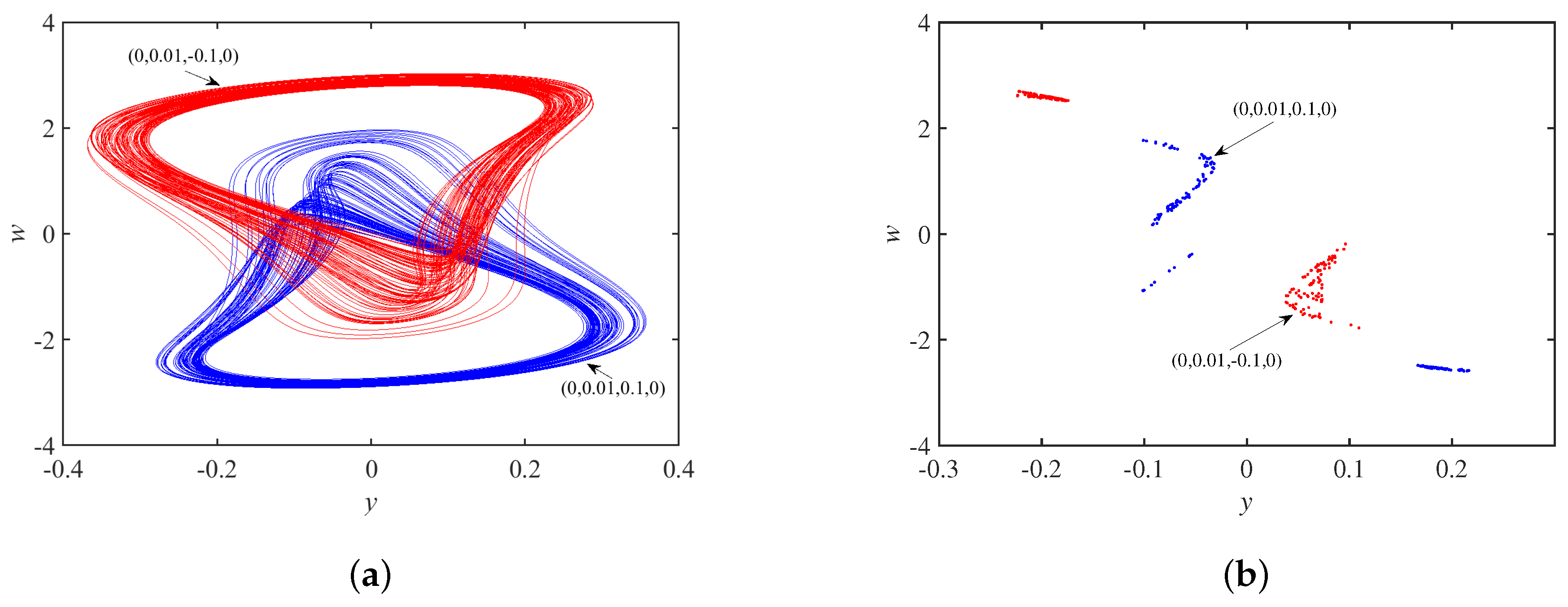
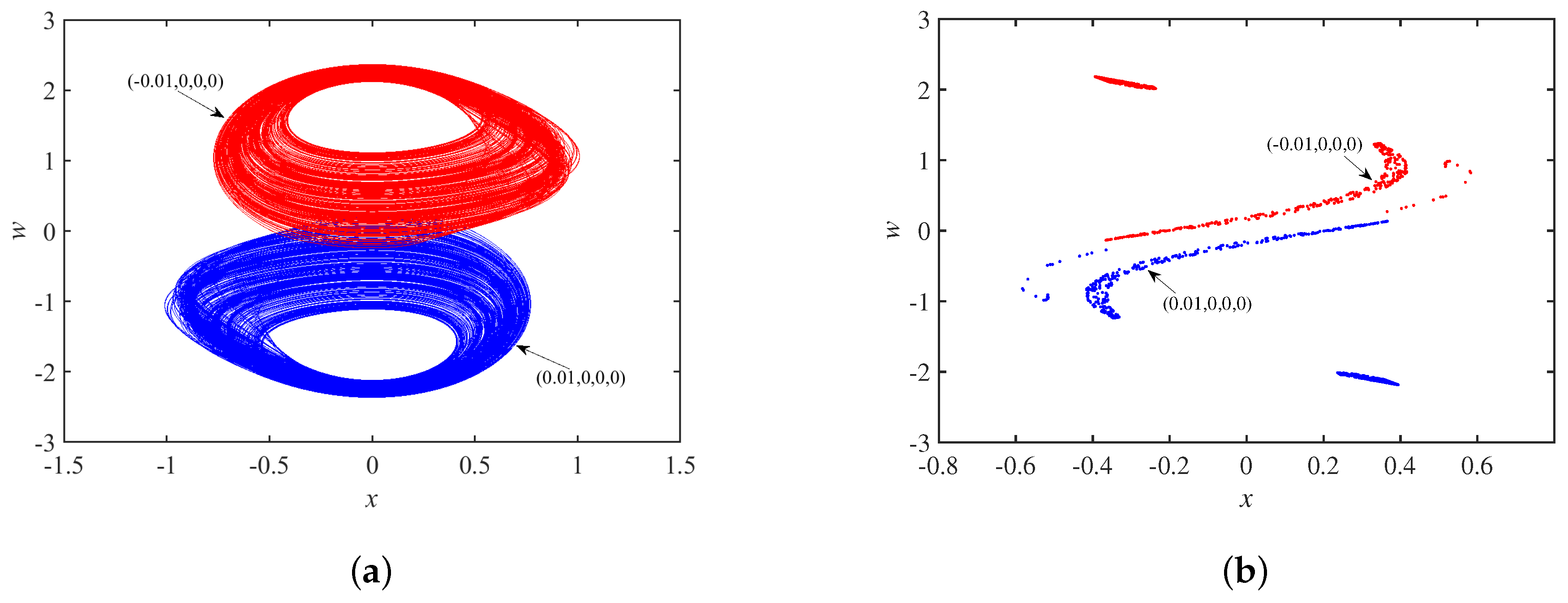
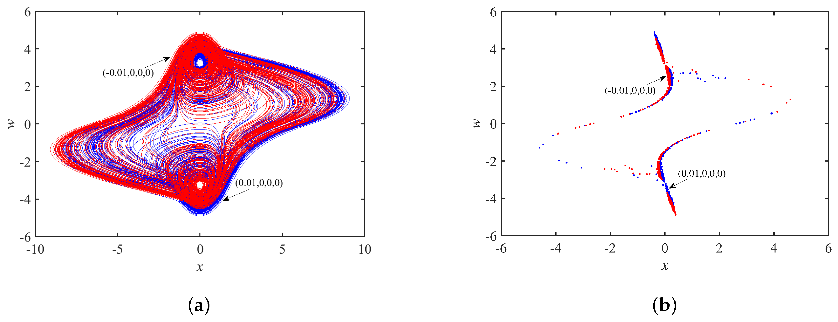
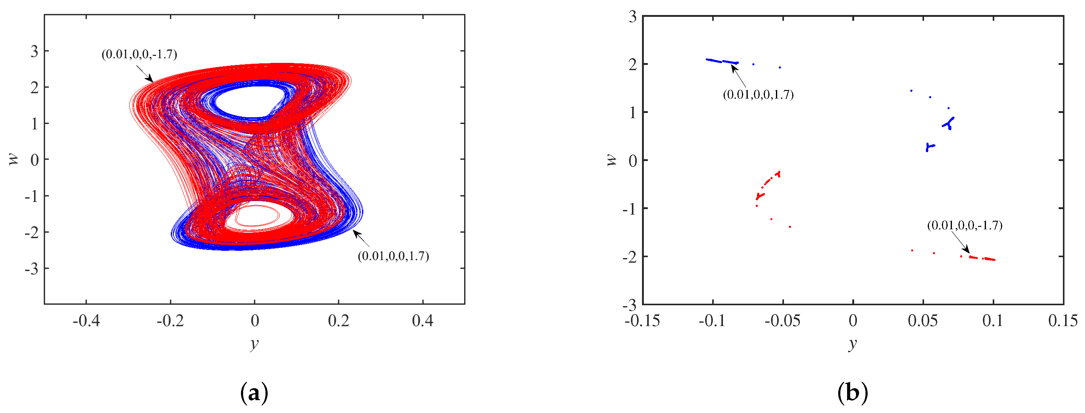
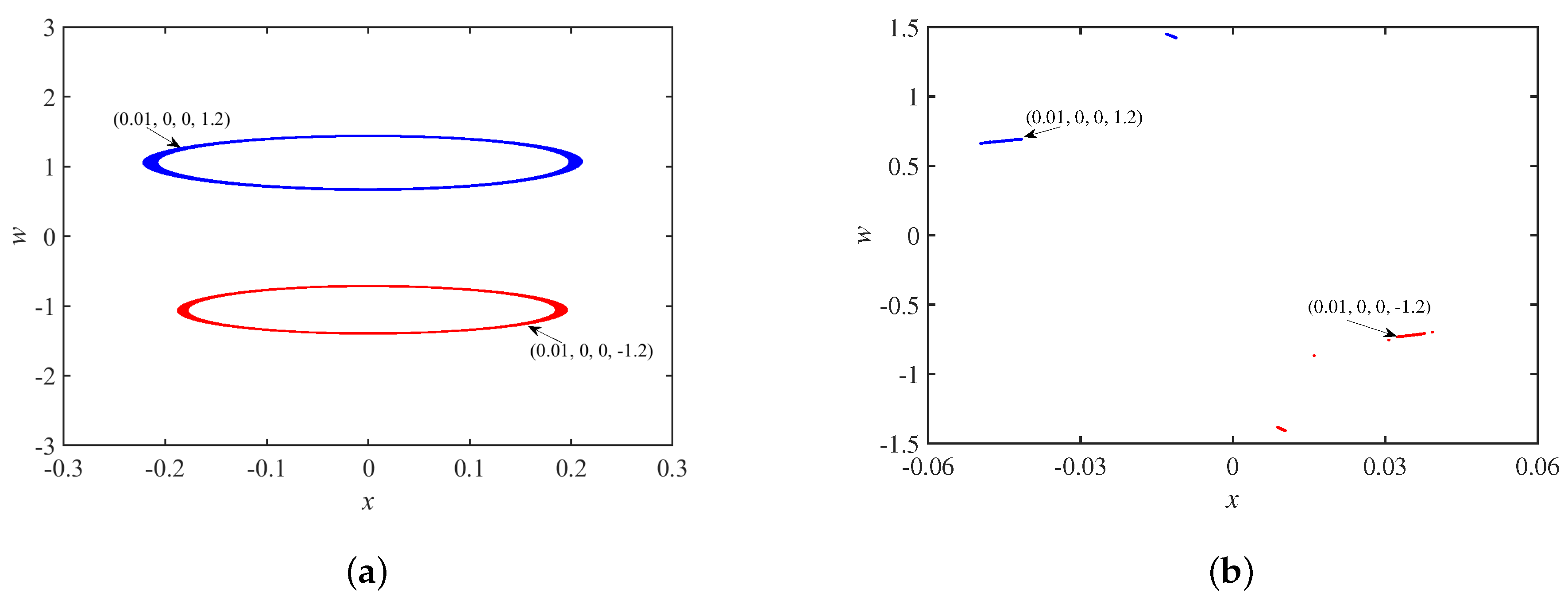
3.2. Dynamics Analysis with Initial Values

Setting the parameter set S = a , b , c , A a = 40 , b = 15 , c = 0.2 , A u = 3.2 , The Lyapunov exponents spectrum with the initial state u 1 0 is shown in Figure 6a, where the smallest Lyapunov exponents is omitted, and the bifurcation diagram corresponding to the y = 0 cross section is shown in Figure 6b. Keeping the same parameter set, the spectrum of Lyapunov exponents and bifurcation diagrams with the initial state u 2 0 are shown in Figure 7, and the spectrum of Lyapunov exponents and bifurcation diagrams with the initial state u 3 0 are shown in Figure 8.

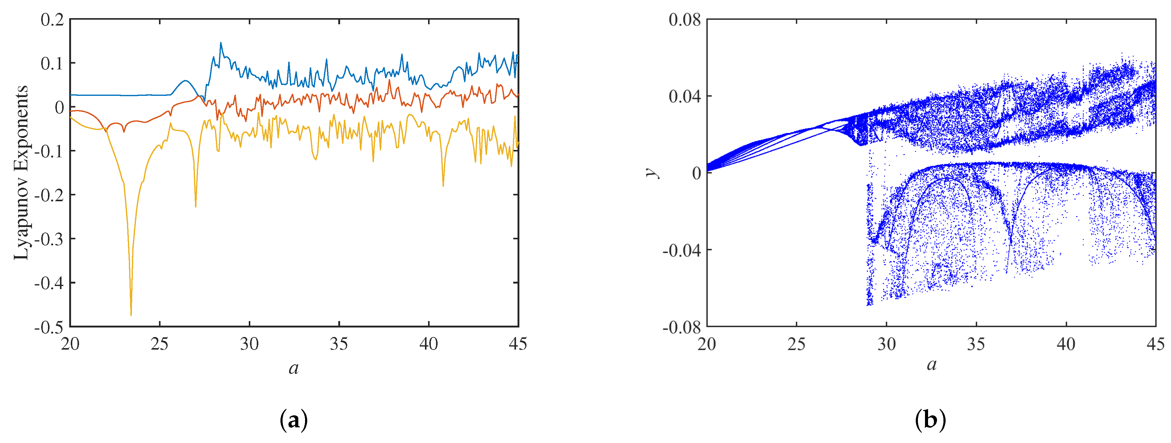
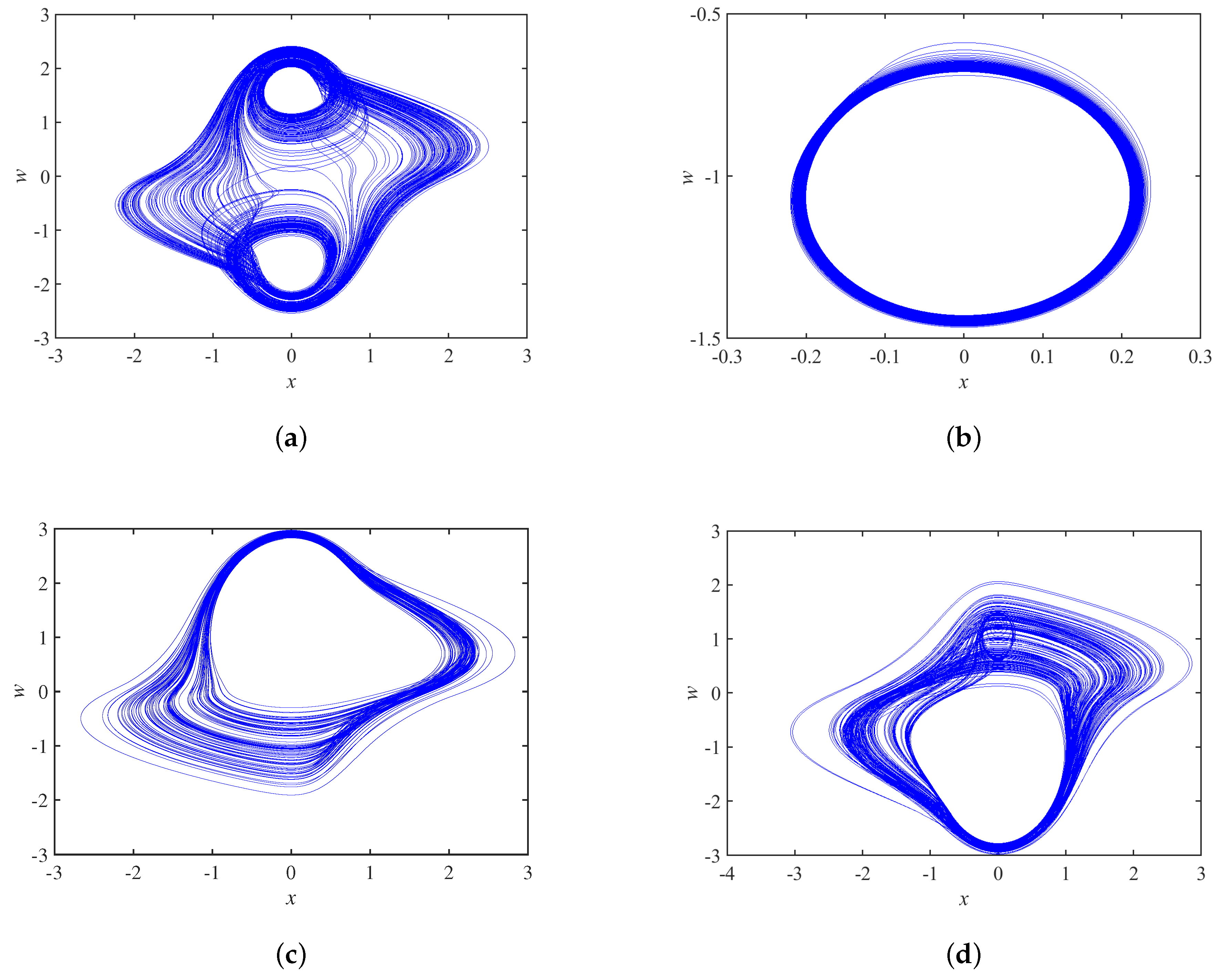
3.3. Dynamic Analysis of Circuit Parameter Variation

When setting the circuit parameters b = 0.15 , c = 0.2 , A u = 3.2 , the initial state as 0.01 , 0 , 0 , 0 , the Lyapunov exponents spectrum with the circuit parameter a is shown in Figure 9a, and the corresponding bifurcation diagram is shown in Figure 9b. The phase trajectory of the system is initially a periodic limit cycle, and it evolves as a single-scroll attractor at a = 27 and as a double-scroll attractor at a = 30 . It is also observed that there are several narrow period-windows in the chaotic region.
Setting the circuit parameters a = 40 , b = 0.15 , A u = 3.2 , the initial state as 0.01 , 0 , 0 , 0 , the Lyapunov exponents spectrum about the circuit parameter c is shown in Figure 10a, and the corresponding bifurcation diagram is shown in Figure 10b. Initially, the phase trajectory of the system behaves as a double-scroll attractor, and it evolves into a limit cycle when c = 0.171 and a sink when c = 0.153 .

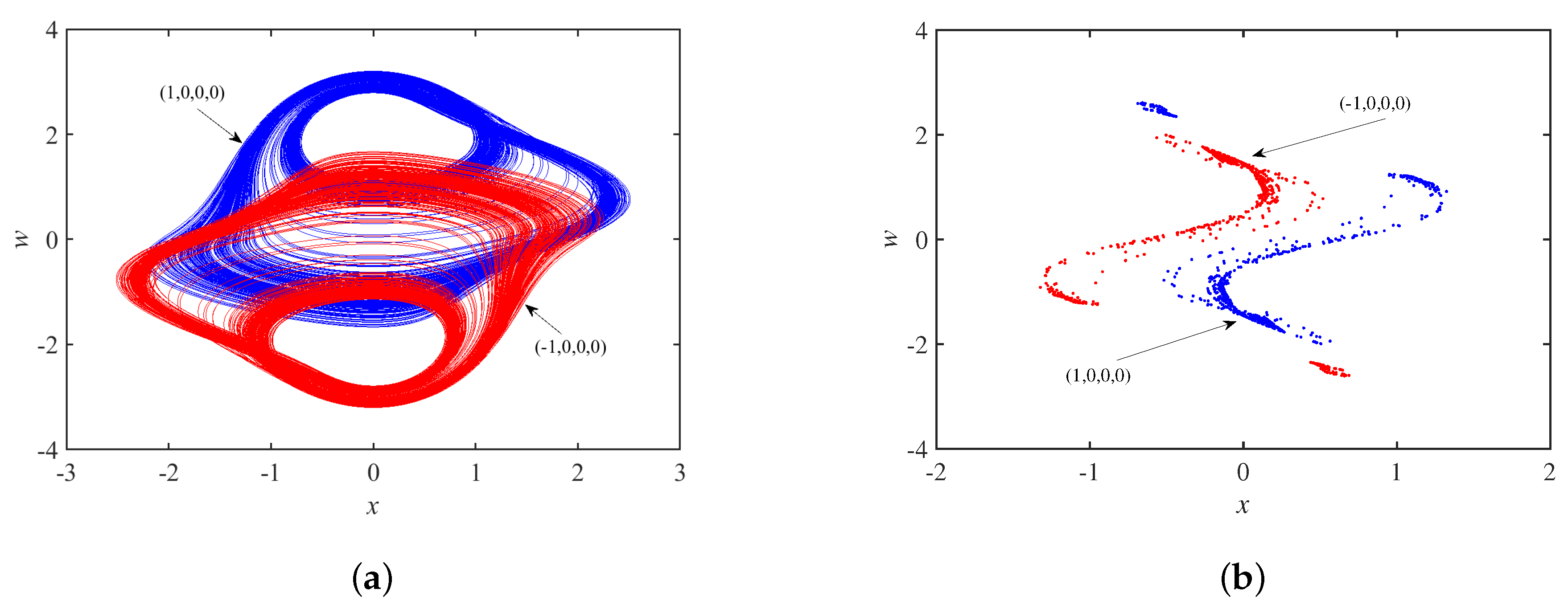
3.4. Coexistence Phenomenon

Setting the parameter set S and the initial state as ± 1 , 0 , 0 , 0 , Figure 11a shows coexisting single-scroll attractors, and the corresponding Poincaré maps in the x w plane is in Figure 11b, which are centrosymmetric about the origin. In other words, the system is chaotic under these conditions. Set the parameter set S and the initial state as 0 , 0.01 , ± 0.1 , 0 . Figure 12a shows asymmetric coexisting single-scroll attractors, and the corresponding to Poincaré maps y w plane is in Figure 12b.
In Figure 13a, the phase trajectory of the system is a coexisting single-scroll attractor when the circuit parameters are set to a = 29 , b = 0.15 , c = 0.2 , A u = 3.2 , and the initial state is ± 0.01 , 0 , 0 , 0 . Selecting the z = 0 cross section, the Poincaré maps corresponding to x w plane are in Figure 13b, and it can be seen that the two coexisting single-scroll attractors are centrosymmetric about the origin.
In Figure 14a, the phase trajectory of the system is a coexisting double-scroll attractor when the circuit parameters are set to a = 33 , b = 0.15 , c = 0.2 , A u = 3.2 and the initial state is ± 0.01 , 0 , 0 , 0 . Selecting the z = 0 cross section, the Poincaré maps corresponding to x w plane is in Figure 14b, and the two coexisting double-scroll attractors are centrosymmetric about the origin.
When the circuit parameters are set to a = 40 , b = 0.15 , c = 0.25 , A u = 3.2 and the initial state is set to ± 0.01 , 0 , 0 , 0 , the phase trajectory of the system is a coexisting double-scroll attractor in Figure 15a. The y = 0 cross section is selected, and the Poincaré maps corresponding to the x w plane are in Figure 15b, which shows that the two coexisting double-scroll attractors are also centrosymmetric about the origin.
The dynamic behaviors with the change of circuit paramaters are summarized in Table 1.

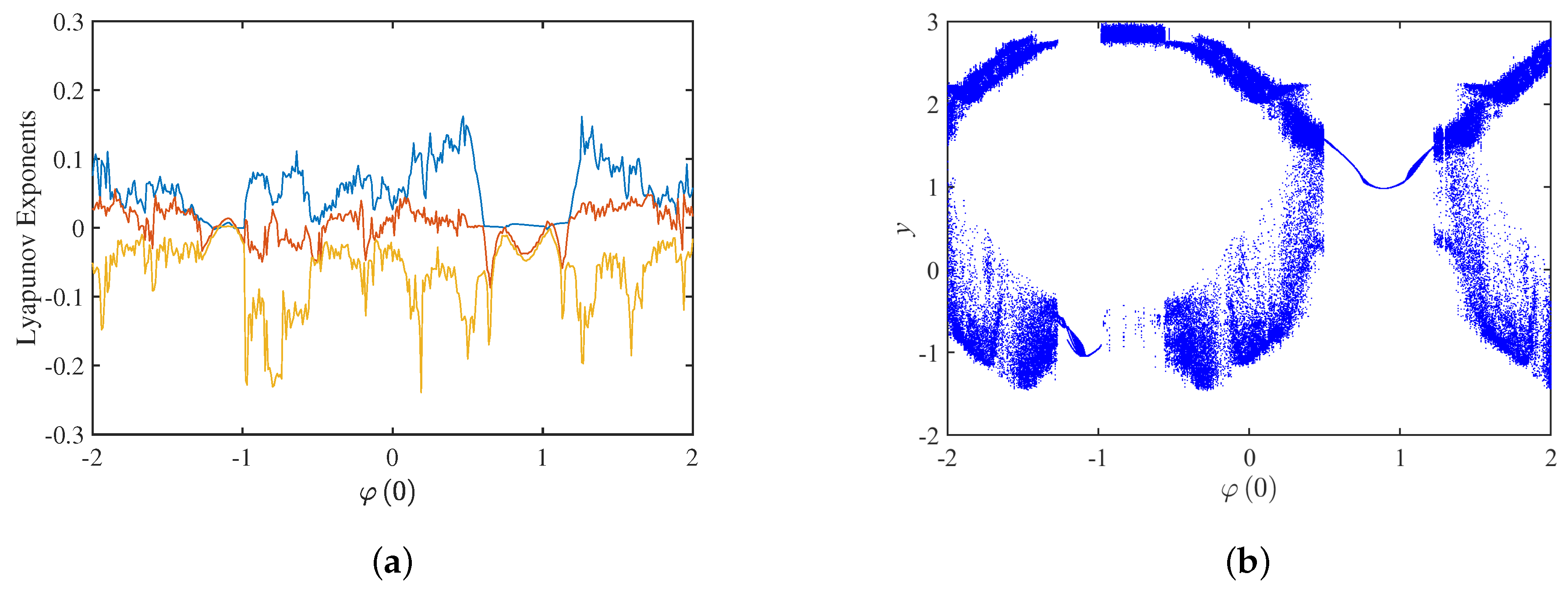
4. The Complex Dynamical Behavior Exhibited by the Change of Initial State φ(0)

The parameters are set to a = 40 , b = 0.15 , c = 0.2 , A = 3.2 , but initial state φ 0 is variable. The bifurcation diagram and Lyapunov exponents spectrum with the initial state φ 0 in the interval 2 , 2 are shown in Figure 16. Only three Lyapunov exponents are shown in Figure 16a, and the fourth negative Lyapunov exponent is omitted for the convenience of observation. Figure 16b shows the bifurcation diagram with φ 0 when the z = 0 cross section is selected. The bifurcation diagram is consistent with the Lyapunov exponents spectrum, and the system exhibits complex dynamical behavior as the initial state φ 0 increases. When φ 0 is in the interval 1.271 , 0.982 , 0.493 , 1.237 and 1.263 , 1.298 , the trajectory of the system behaves as a periodic limit cycle. When φ 0 is in the interval 2 , 1.272 , 0.981 , 0.367 , 0.366 , 0.492 , 1.238 , 1.240 , 1.299 , 1.390 and 1.391 , 2 , the system is chaotic. When φ 0 is in the interval 1.241 , 1.262 , it is a periodic-window. The results are shown in Table 2.
The phase trajectories with different φ 0 are shown in Figure 17, and the system exhibits a double-scroll attractor when φ 0 = 1.77 , it is a periodic limit cycle when φ 0 = 1.23 , and it is a single-scroll attractor when φ 0 = 0.98 , φ 0 = 1.24 .
Figure 18a shows the coexistence of two double-scroll attractors when the initial state φ 0 = ± 1.7 , and the corresponding Poincaré maps are in Figure 18b. Figure 19a demonstrates the coexistence of the periodic limit cycle when the initial state φ 0 = ± 1.2 , and the corresponding Poincaré maps are in Figure 19b.

5. Conclusions

The RC bridge oscillation chaotic circuit based on the physical memristor is proposed to fill the vacancy in the experiment teaching system of Electrical and Electronic Technology. Some dynamic behaviors of the circuit system have been researched. By changing the initial values and circuit parameters, the system exhibits the dynamical behaviors of single-scroll coexistence, double-scroll coexistence, and limit–cycle coexistence. This experiment is rigorously designed to stimulate students to expand their knowledge system and promote the application of memristor in experimental teaching.

Author Contributions

Conceptualization, G.D.; methodology, Y.Z.; software, H.Y.; investigation, Y.Z., H.Y. and M.H.; data curation, Y.Z.; writing—original draft preparation, G.D. and Y.Z.; writing—review and editing, M.G. and W.G.; supervision, M.G.; project administration, G.D. All authors have read and agreed to the published version of the manuscript.

Funding

This work was supported by the National Natural Science Foundation of China (Grant Nos. 62176143, 61603246), the Natural Science Foundation of Shandong Province (ZR2022MF225, ZR2021MF001), the Talented Young Teachers Training Program of Shandong University of Science and Technology (BJ20200507), and the Excellent Teaching Team Training Plan Project of Shandong University of Science and Technology (TD20221101).

Data Availability Statement

The data supporting the SBT memristor and the mathematical model of memristor are publicly available in two articles (Reference to [44,45]).

Conflicts of Interest

The authors declare no conflict of interest.

Nomenclature

NameImplication
SBT S r 0.97 B a 0.03 T i O 3 δ
A u The amplification of OP-AMP1
a C 2 C 1
b R 2 R 1
c R 2 R m n
u 1 t The voltage of the capacitor C 1
u 2 t The voltage of the capacitor C 2
u 3 t The voltage of the capacitor C 3
φ t The internal flux of the SBT memristor

References

  1. Chua, L. Memristor-The missing circuit element. IEEE Trans. Circuit Theory 1971, 18, 507–519. [Google Scholar] [CrossRef]
  2. Strukov, D.B.; Snider, G.S.; Stewart, D.R.; Williams, R.S. The missing memristor found. Nature 2008, 453, 80–83. [Google Scholar] [CrossRef] [PubMed]
  3. Torrezan, A.C.; Strachan, J.P.; Medeiros, R.G.; Williams, R.S. Sub-nanosecond switching of a tantalum oxide memristor. Nanotechnology 2011, 22, 485203. [Google Scholar] [CrossRef] [PubMed]
  4. Kim, H.; Choi, M.J.; Suh, J.M.; Han, J.S.; Kim, S.G.; Jang, H.W. Quasi-2D halide perovskites for resistive switching devices with ON/OFF ratios above 109. NPG Asia Mater. 2020, 12, 21. [Google Scholar]
  5. Almadhoun, M.N.; Speckbacher, M.; Olsen, B.C.; Luber, E.J.; Sayed, S.Y.; Tornow, M.; Buriak, J.M. Bipolar resistive switching in junctions of gallium Oxide and p-type silicon. Nano Lett. 2021, 21, 2666–2674. [Google Scholar] [CrossRef]
  6. Jiao, M.; Wang, D. The Savitzky-Golay filter based bidirectional long short-term memory network for SOC estimation. Int. J. Energy Res. 2021, 45, 19467–19480. [Google Scholar] [CrossRef]
  7. Qian, W.; Xing, W.; Fei, S. H state estimation for neural networks with general activation function and mixed time-varying delays. IEEE Trans. Neural Netw. Learn Syst. 2021, 32, 3909–3918. [Google Scholar] [CrossRef]
  8. Jiao, M.; Wan, G.; Guo, Y.; Wang, D.; Liu, H.; Xiang, J.; Liu, F. A graph Fourier transform based bidirectional long short-term memory neural network for electrophysiological source imaging. Front. Neurosci. 2022, 16, 867466. [Google Scholar] [CrossRef]
  9. Dou, G.; Zhao, K.; Guo, M.; Mou, J. Memristor-based LSTM Network for Text Classification. Fractals, 2023; accepted papers. [Google Scholar] [CrossRef]
  10. Ma, T.; Mou, J.; Yan, H.; Cao, Y. A New Class of Hopfield Neural Network with Double Memristive Synapses and Its DSP Implementation. Eur. Phys. J. Plus 2022, 137, 1135. [Google Scholar] [CrossRef]
  11. Chua, L. Everything you wish to know about memristors but are afraid to ask. Radioengineering 2015, 24, 319–368. [Google Scholar] [CrossRef]
  12. Zhang, X.; Wang, W.; Liu, Q.; Zhao, X.; Wei, J.; Cao, R.; Yao, Z.; Zhu, X.; Zhang, F.; Lv, H.; et al. An artificial neuron based on a threshold switching memristor. IEEE Electron. Device Lett. 2018, 39, 308–311. [Google Scholar]
  13. Zhou, G.; Wang, Z.; Sun, B.; Zhou, F.; Sun, L.; Zhao, H.; Hu, X.; Peng, X.; Yan, J.; Wang, H.; et al. Volatile and nonvolatile memristive devices for neuromorphic computing. Adv. Electron. Mater. 2022, 8, 2101127. [Google Scholar] [CrossRef]
  14. Li, C.; Yang, Y.; Yang, X.; Zi, X.; Xiao, F. A tristable locally active memristor and its application in Hopfield neural network. Nonlinear Dyn. 2022, 108, 1697–1717. [Google Scholar]
  15. Yao, L.; Liu, P.; Wu, J.; Han, Y.; Zhong, Y.; You, Z. Integrating Two Logics Into One Crossbar Array for Logic Gate Design. IEEE Trans. Circuits Syst. II Express Briefs. 2021, 68, 2987–2991. [Google Scholar]
  16. Wang, X.; Dong, C.; Zhou, P.; Nandi, S.K.; Nath, S.K.; Elliman, R.G.; Lu, H.H.C. Kang, S.; Eshraghian, J.K. Low-Variance Memristor-based Multi-Level Ternary Combinational Logic. IEEE Trans. Circuits Syst. I Regul. Pap. 2022, 69, 2423–2434. [Google Scholar] [CrossRef]
  17. Wang, X.; Zhou, P.; Eshraghian, J.K.; Li, C.; Iu, H.H.C.; Chang, T.; Kang, S. High-Density Memristor-CMOS Ternary Logic Family. IEEE Trans. Circuits Syst. I Regul. Pap. 2021, 68, 264–274. [Google Scholar]
  18. Liu, G.; Zheng, L.; Wang, G.; Shen, Y.; Liang, Y. A Carry Lookahead Adder Based on Hybrid CMOS-Memristor Logic Circuit. IEEE Access 2019, 7, 43691–43696. [Google Scholar]
  19. Guo, M.; Liu, R.; Dou, M.; Dou, G. An SBT-memristor-based crossbar memory circuit. Chin. Phys. B 2021, 30, 068402. [Google Scholar] [CrossRef]
  20. Guo, M.; Zhu, Y.; Liu, R.; Zhao, K.; Dou, G. An associative memory circuit based on physical memristors. Neurocomputing 2022, 472, 12–23. [Google Scholar]
  21. Hong, Q.; Chen, H.; Sun, J. Memristive Circuit Implementation of a Self-Repairing Network Based on Biological Astrocytes in Robot Application. IEEE Trans. Neural Netw. Learn Syst. 2022, 33, 2106–2120. [Google Scholar] [CrossRef] [PubMed]
  22. Bao, B.; Zhu, Y.; Ma, M.; Bao, H.; Wu, H.; Chen, M. Memristive neuron model with an adapting synapse and its hardware experiments. Sci. China Technol. Sci. 2021, 64, 1107–1117. [Google Scholar] [CrossRef]
  23. Dou, G.; Dou, M.; Liu, R.; Guo, M. Artifificial synaptic behavior of the SBT-memristor. Chin. Phys. B 2021, 30, 078401. [Google Scholar] [CrossRef]
  24. Yang, J.; Chen, G.; Wen, S. Finite-time dissipative control for bidirectional associative memory neural networks with state-dependent switching and time-varying delays. Knowl. Based Syst. 2022, 252, 109338. [Google Scholar]
  25. Guo, M.; Sun, Y.; Zhu, Y.; Han, M.; Dou, G.; Wen, S. Pruning and Quantization Algorithm with Applications in Memristor-based Convolutional Neural Network. Cogn. Neurodyn. 2023, 1–13. [Google Scholar] [CrossRef]
  26. Lai, Q.; Wan, Z.; Kengne, L.K.; Kuate, P.D.K.; Chen, C. Two-Memristor-Based Chaotic System With Infinite Coexisting Attractors. IEEE Trans. Circuits Syst. II Express Briefs. 2021, 68, 2197–2201. [Google Scholar]
  27. Peng, Y.; He, S.; Sun, K. A higher dimensional chaotic map with discrete memristor. Int. J. Electron. Commun. 2021, 129, 153539. [Google Scholar] [CrossRef]
  28. Vadivel, R.; Sabarathinam, S.; Wu, Y.; Chaisena, K.; Gunasekaran, N. New results on T–S fuzzy sampled-data stabilization for switched chaotic systems with its applications. Chaos Solitons Fractals 2022, 164, 112741. [Google Scholar] [CrossRef]
  29. Han, X.; Mou, J.; Jahanshahi, H.; Cao, Y.; Bu, F. A New Set of Hyperchaotic Maps Based on Modulation and Coupling. Eur. Phys. J. Plus 2022, 137, 523. [Google Scholar] [CrossRef]
  30. Sha, Y.; Sun, B.; Chen, X.; Mou, J.; Jahanshahi, H. A Chaotic Image Encryption Scheme Based on Genetic Central Dogma and KMP Method. Int. J. Bifurcat. Chaos 2022, 32, 2250186. [Google Scholar] [CrossRef]
  31. Liu, X.; Mou, J.; Yan, H.; Bi, X. Memcapacitor-Coupled Chebyshev Hyperchaotic Map. Int. J. Bifurcat. Chaos 2022, 32, 2250180. [Google Scholar] [CrossRef]
  32. Guo, M.; Gao, Z.; Xue, Y.; Dou, G.; Li, Y. Dynamics of a physical SBT memristor-based Wien-bridge circuit. Nonlinear Dyn. 2018, 93, 1681–1693. [Google Scholar] [CrossRef]
  33. Wu, H.; Zhou, J.; Chen, M.; Xu, Q.; Bao, B. DC-offset induced asymmetry in memristive diode-bridge-based Shinriki oscillator. Chaos Solitons Fractals 2022, 154, 111624. [Google Scholar] [CrossRef]
  34. Dou, G.; Duan, H.; Yang, W.; Yang, H.; Guo, M.; Li, Y. Effects of initial conditions and circuit parameters on the SBT-memristor-based chaotic circuit. Int. J. Bifurcat. Chaos 2019, 29, 1950171. [Google Scholar]
  35. Dou, G.; Yang, H.; Gao, Z.; Li, P.; Dou, M.; Yang, W.; Guo, M.; Li, Y. Coexisting Multi-Dynamics of a Physical SBT Memristor-Based Chaotic Circuit. Int. J. Bifurcat. Chaos 2020, 30, 2030043. [Google Scholar] [CrossRef]
  36. Ren, L.; Mou, J.; Banerjee, S.; Zhang, Y. A Hyperchaotic Map with A New Discrete Memristor Model: Design, Dynamical Analysis, Implementation and Application. Chaos Solitons Fractals 2023, 167, 113024. [Google Scholar] [CrossRef]
  37. Li, C.; Li, H.; Xie, W.; Du, J. A S-type bistable locally active memristor model and its analog implementation in an oscillator circuit. Nonlinear Dyn. 2021, 106, 1041–1058. [Google Scholar] [CrossRef]
  38. Li, H.; Li, C.; Du, J. Discretized locally active memristor and application in logarithmic map. Nonlinear Dyn. 2023, 111, 2895–2915. [Google Scholar] [CrossRef]
  39. Guo, M.; Yang, W.; Xue, Y.; Gao, Z.; Yuan, F.; Dou, G.; Li, Y. Multistability in a physical memristor-based modified Chua’s circuit. Chaos 2019, 29, 043114. [Google Scholar] [CrossRef] [PubMed]
  40. Bao, B.; Jiang, P.; Wu, H.; Hu, F. Complex transient dynamics in periodically forced memristive Chua’s circuit. Nonlinear Dyn. 2015, 79, 2333–2343. [Google Scholar]
  41. Fitch, A.L.; Yu, D.; Herbert, H.C.I.; Sreeram, V. Hyperchaos in a memristor-based modified canonical Chua’s circuit. Int. J. Bifurcat. Chaos 2012, 22, 1250133. [Google Scholar] [CrossRef]
  42. Simmons, D.R.; Clegorne, N.; Polmear, M. Uncovering the Hidden Curriculum of Leadership Education in Civil Engineering. Int. J. Eng. Educ. 2022, 38, 224–236. [Google Scholar]
  43. Rajagopal, K.; Karthikeyan, A.; Srinivasan, A. Dynamical analysis and FPGA implementation of a chaotic oscillator with fractional-order memristor components. Nonlinear Dyn. 2018, 91, 1491–1512. [Google Scholar]
  44. Dou, G.; Yu, Y.; Guo, M.; Zhang, Y.; Sun, Z.; Li, Y. Memristive Behavior Based on Ba-Doped SrTiO3 Films. Chin. Phys. Lett. 2017, 34, 038502. [Google Scholar] [CrossRef]
  45. Guo, M.; Zhu, Y.; Yang, R.; Zhang, M.; Zhao, K.; Yang, H.; Dou, G. A single-T chaotic circuit based on a physical memristor. Eur. Phys. J. Spec. Top. 2022, 231, 3163–3170. [Google Scholar] [CrossRef]
Figure 1. Chaotic circuit based on a quadratic smooth model of an SBT memristor.
Micromachines 14 00410 g001
Figure 2. The three-dimensional phase portrait of the chaotic circuit system.
Micromachines 14 00410 g002
Figure 3. Phase portrait of the proposed chaotic system on (a) x–z plane, (b) y–x plane, (c) y–z plane, and (d) w–x plane.
Micromachines 14 00410 g003
Figure 4. Poincaré maps: (a) y = 0; (b) x = 0.
Micromachines 14 00410 g004
Figure 5. Dynamic behavior of circuit system with τ : (a) Lyapunov exponents spectrum; (b) time domain waveform.
Micromachines 14 00410 g005
Figure 6. Dynamics analysis under the initial state u 1 0 : (a) Lyapunov exponents spectrum; (b) bifurcation diagram.
Micromachines 14 00410 g006
Figure 7. Dynamics analysis under initial state u 2 0 : (a) Lyapunov exponents spectrum; (b) bifurcation diagram.
Micromachines 14 00410 g007
Figure 8. Dynamics with under initial state u 3 0 : (a) Lyapunov exponents spectrum; (b) bifurcation diagram.
Micromachines 14 00410 g008
Figure 9. Dynamics analysis with parameter a: (a) Lyapunov exponents spectrum; (b) bifurcation diagram.
Micromachines 14 00410 g009
Figure 10. Dynamic analysis with parameter c: (a) Lyapunov exponents spectrum; (b) bifurcation diagram.
Micromachines 14 00410 g010
Figure 11. Dynamics behavior with initial state u 1 0 : (a) coexisting single-scroll attractors; (b) Poincaré maps.
Micromachines 14 00410 g011
Figure 12. Dynamics behavior with initial state u 3 0 : (a) coexisting single-scroll attractors; (b) Poincaré maps.
Micromachines 14 00410 g012
Figure 13. When a = 29 , b = 0.15 , c = 0.2 : (a) coexisting single-scroll attractors; (b) Poincaré maps.
Micromachines 14 00410 g013
Figure 14. When a = 33 , b = 0.15 , c = 0.2 : (a) coexisting double-scroll attractors; (b) Poincaré maps.
Micromachines 14 00410 g014
Figure 15. When a = 40 , b = 0.15 , c = 0.25 : (a) coexisting double-scroll attractors; (b) Poincaré maps.
Micromachines 14 00410 g015
Figure 16. Dynamics analysis with initial state φ 0 : (a) Lyapunov exponents spectrum; (b) bifurcation diagram.
Micromachines 14 00410 g016
Figure 17. Phase portraits of initial state φ 0 at different values on plane x w : (a) φ 0 = −1.77; (b) φ 0 = −1.23; (c) φ 0 = −0.98 and (d) φ 0 = 1.24.
Micromachines 14 00410 g017
Figure 18. When φ 0 = ± 1.7 : (a) coexisting double-scroll attractors; (b) Poincaré maps.
Micromachines 14 00410 g018
Figure 19. When φ 0 = ± 1.2 : (a) coexisting periodic limit cycle; (b) Poincaré maps.
Micromachines 14 00410 g019
Table 1. The values of circuit parameters for various dynamical behaviors.
Values of Circuits ParametersDynamical Behaviors
a = 29 , b = 0.15 , c = 0.2 , A u = 3.2 Coexisting single-scroll attractors
a = 33 , b = 0.15 , c = 0.2 , A u = 3.2 Coexisting double-scroll attractors
a = 40 , b = 0.15 , c = 0.25 , A u = 3.2 Coexisting double-scroll attractors
Table 2. The complex dynamical behavior with the change of Initial state φ 0 .
The Initial StateIntervalDynamics
2 , 1.272 Double-scroll attractor
1.271 , 0.982 Periodic limit cycle
0.981 , 0.367 Single-scroll attractor
0.366 , 0.492 Double-scroll attractor
φ 0 0.493 , 1.237 Periodic limit cycle
1.238 , 1.240 Single-scroll attractor
1.241 , 1.262 Period-window
1.263 , 1.298 Periodic limit cycle
1.299 , 1.390 Single-scroll attractor
1.391 , 2 Double-scroll attractor
Disclaimer/Publisher’s Note: The statements, opinions and data contained in all publications are solely those of the individual author(s) and contributor(s) and not of MDPI and/or the editor(s). MDPI and/or the editor(s) disclaim responsibility for any injury to people or property resulting from any ideas, methods, instructions or products referred to in the content.

