

Investigation on Surface Integrity of Nodular Cast Iron QT700-2 in Shape Adaptive Grinding


Abstract
:1. Introduction
2. Experiment
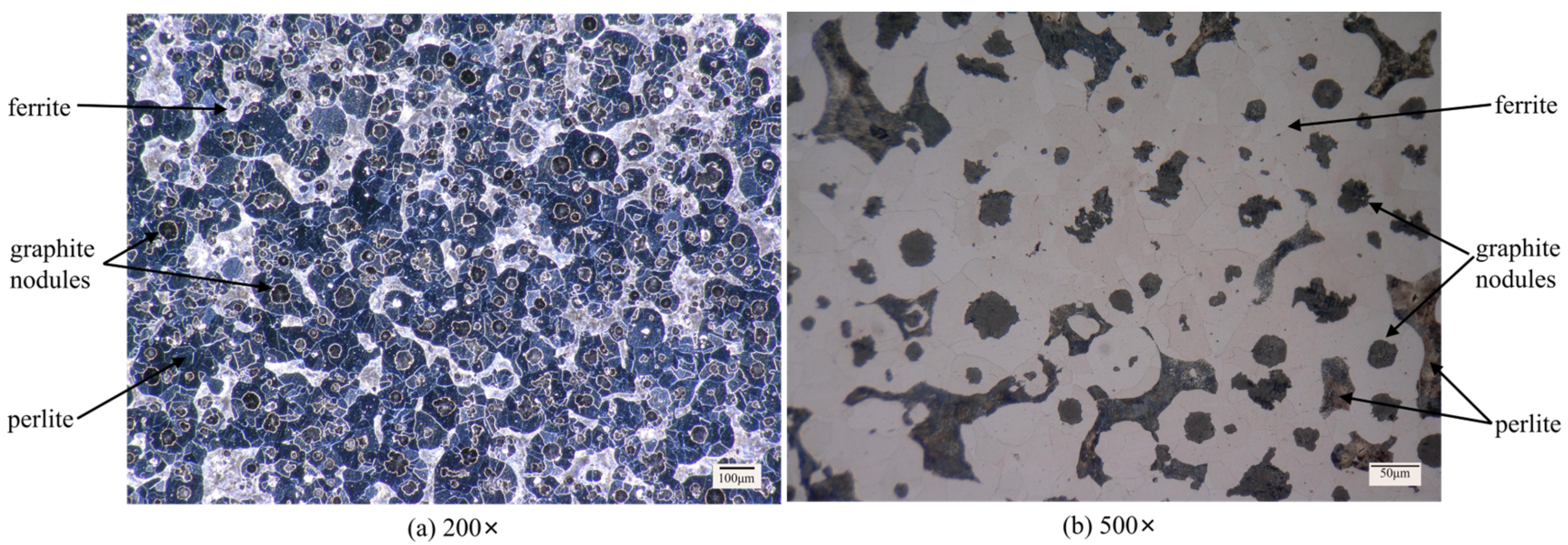
2.1. Workpiece Material
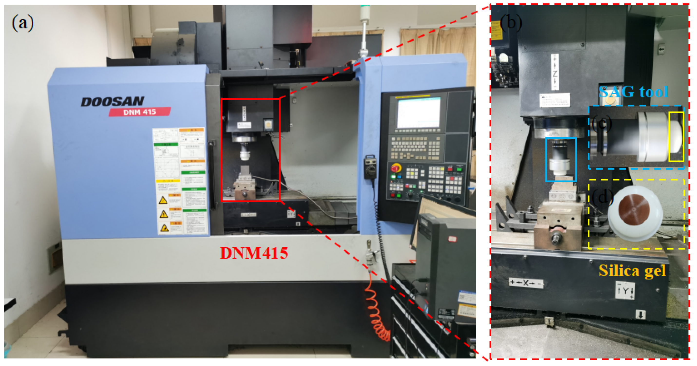
2.2. Experimental Setup
2.3. Experimental Method
2.4. Experimental Data Measurement
3. Results and Discussion
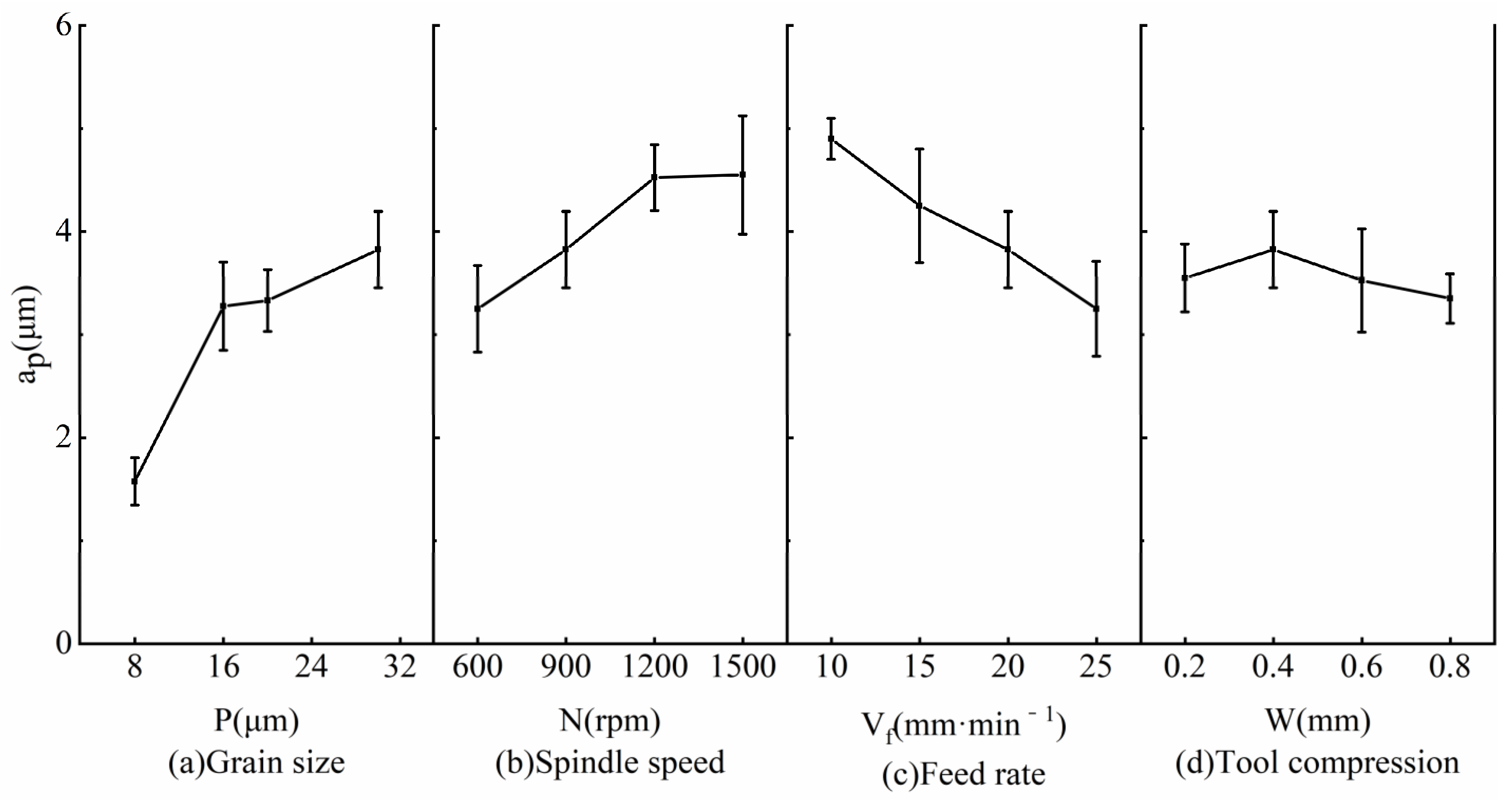
3.1. Grinding Force
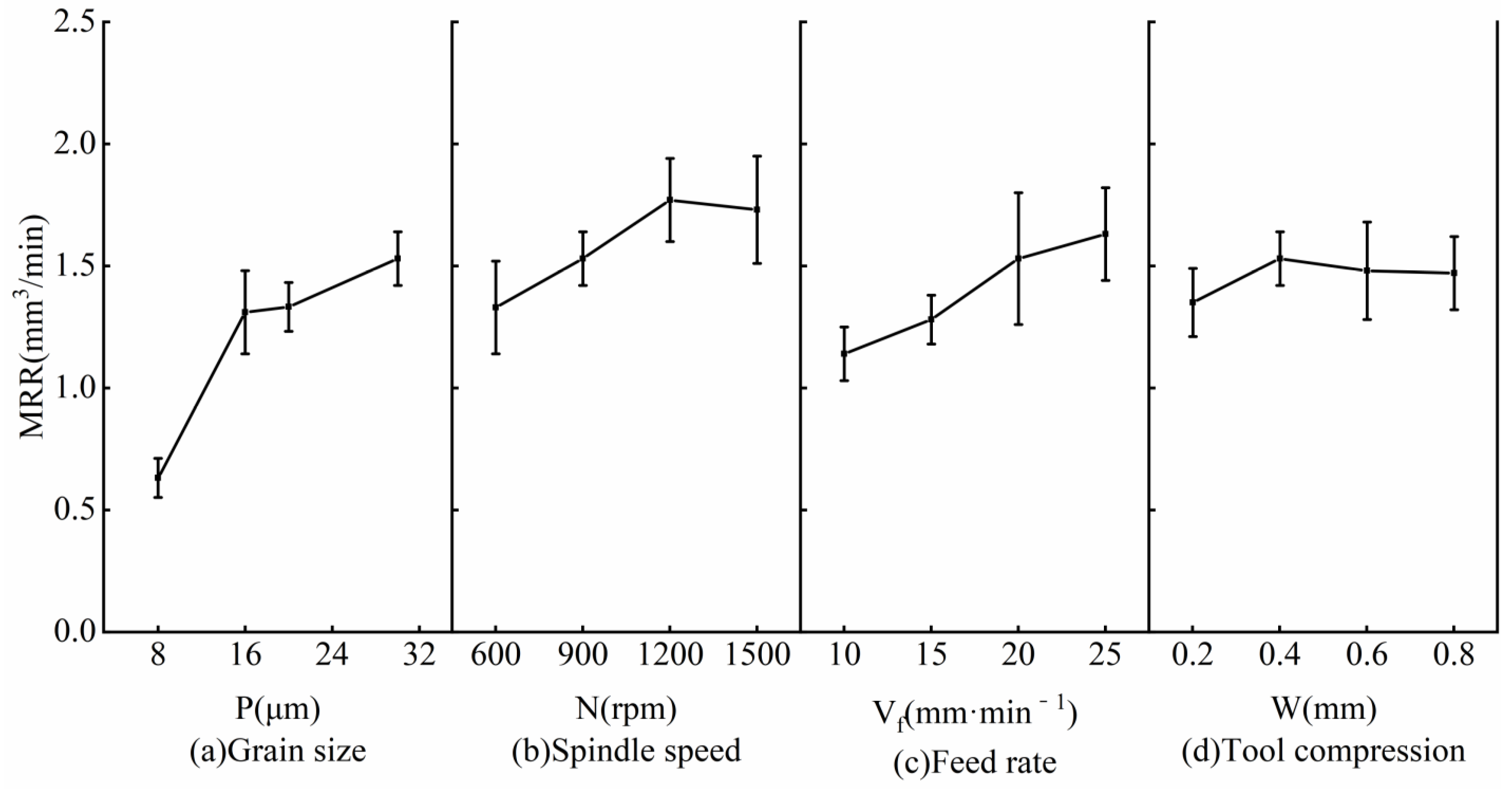
3.2. Material Removal Rate
3.3. Surface Roughness
3.4. Grinding Temperature
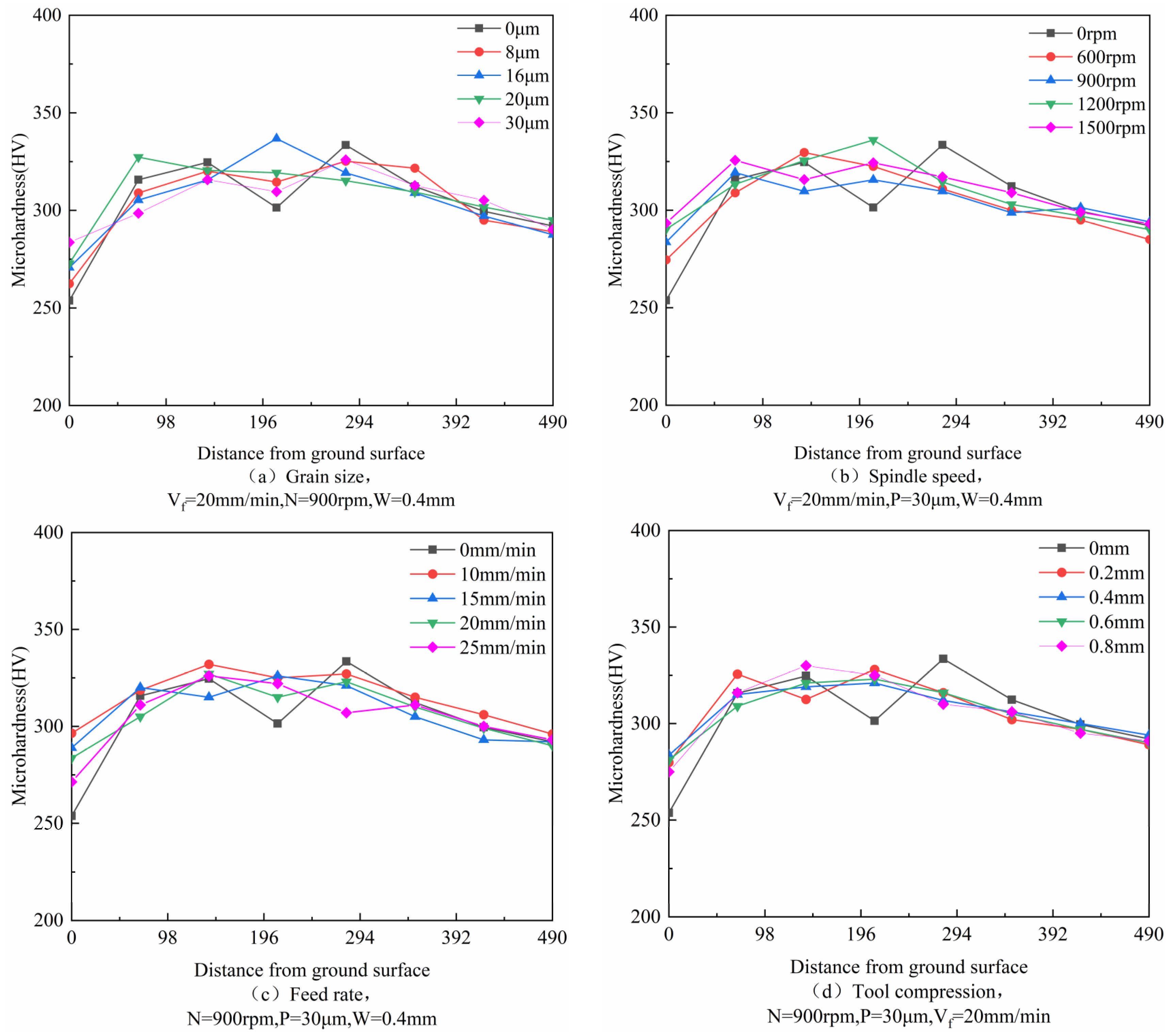
3.5. Work Hardening
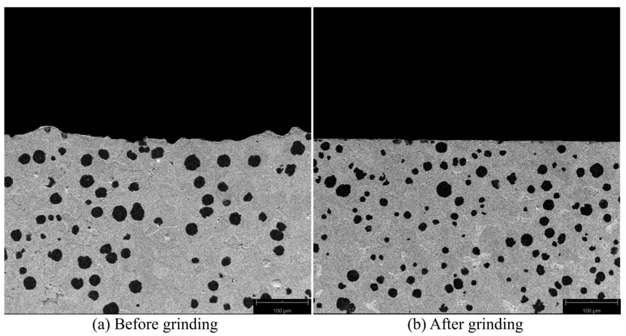
3.6. Microstructure
4. Conclusions
- A spherical SAG tool can be designed to grind arbitrary curved surfaces larger than the curvature of the tool.
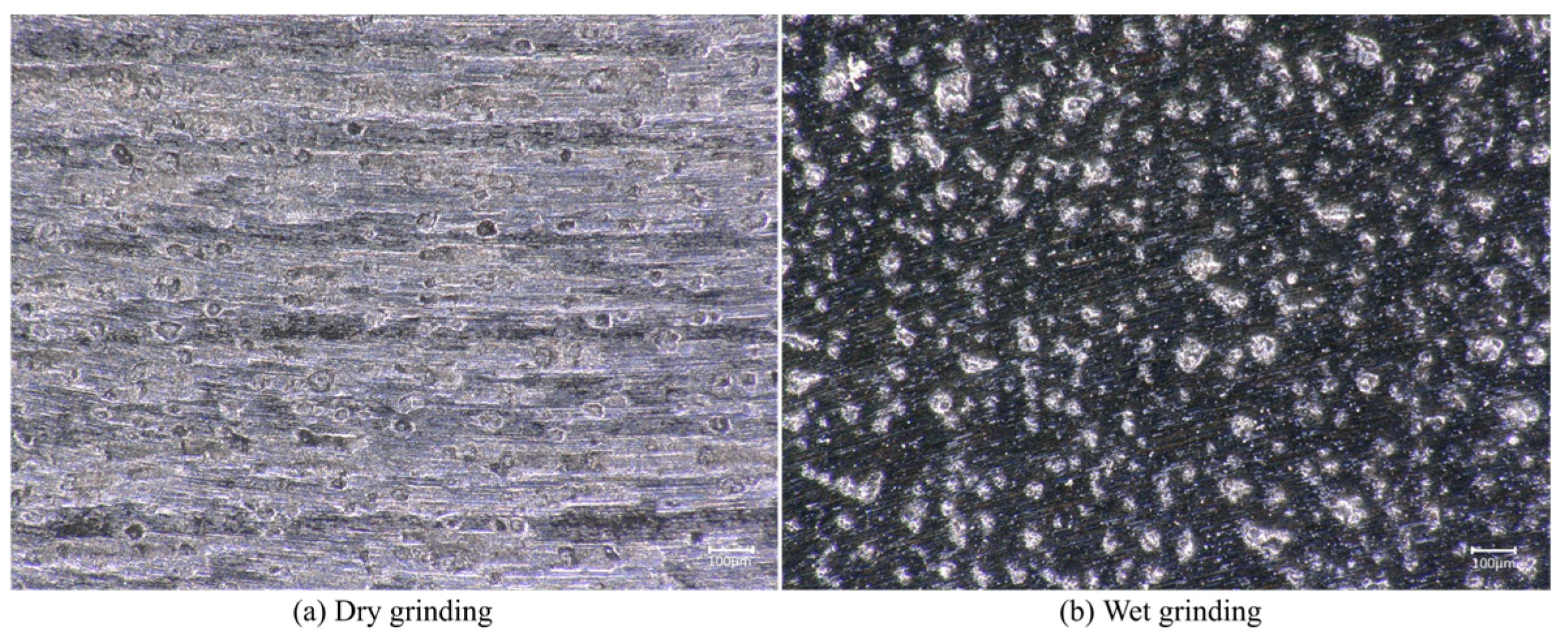
- The grain size in SAG is the main factor affecting the grinding force, material removal rate, and machined surface roughness. The use of cutting fluid can effectively reduce the impact of debris accumulation.
- The grinding force (up to 33 N) and grinding temperature (up to 43.7 °C) of the SAG tool are very low, and the machining influence layer is very small. During grinding, the workpiece material can be mostly removed.
- The recommended parameters of grinding include a grain size of 20 μm, spindle speed of 1500 rpm, feed rate of 10 mm/min, and tool compression of 0.4 mm. After continuous grinding for a period of time, the workpiece surface roughness decreases from Ra 1.541 μm to Ra 0.19 μm, which is lower than the Ra 0.2 μm finishing roughness requirement of the crankshaft.
Author Contributions
Funding
Institutional Review Board Statement
Informed Consent Statement
Data Availability Statement
Acknowledgments
Conflicts of Interest
References
- Yaer, X.; Shimizu, K.; Matsumoto, H.; Kitsudo, T.; Momono, T. Erosive wear characteristics of spheroidal carbides cast iron. Wear 2008, 264, 947–957. [Google Scholar] [CrossRef]
- Zhan, K.; Zhang, Y.; Bao, L.; Yang, Z.; Zhao, B.; Ji, V. Surface characteristic and wear resistance of QT-700-2 nodular cast iron after laser quenching combing with shot peening treatment. Surf. Coat. Technol. 2021, 423, 127589. [Google Scholar] [CrossRef]
- Yigit, R.; Celik, E.; Findik, F.; Koksal, S. Effect of cutting speed on the performance of coated and uncoated cutting tools in turning nodular cast iron. J. Mater. Process. Technol. 2008, 204, 80–88. [Google Scholar] [CrossRef]
- Yigit, R.; Celik, E.; Findik, F.; Koksal, S. Tool life performance of multilayer hard coatings produced by HTCVD for machining of nodular cast iron. Int. J. Refract. Met. Hard Mater. 2008, 26, 514–524. [Google Scholar] [CrossRef]
- Dražumerič, R.; Roininen, R.; Badger, J.; Krajnik, P. Temperature-based method for determination of feed increments in crankshaft grinding. J. Mater. Process. Technol. 2018, 259, 228–234. [Google Scholar] [CrossRef]
- Zhu, W.-L.; Anthony, B. Investigation of critical material removal transitions in compliant machining of brittle ceramics. Mater. Des. 2020, 185, 108258. [Google Scholar] [CrossRef]
- Zhu, W.-L.; Beaucamp, A. Ultra-precision finishing of low expansion ceramics by compliant abrasive technologies: A comparative study. Ceram. Int. 2019, 45, 11527–11538. [Google Scholar] [CrossRef]
- Zhu, W.-L.; Yang, Y.; Li, H.N.; Axinte, D.; Beaucamp, A. Theoretical and experimental investigation of material removal mechanism in compliant shape adaptive grinding process. Int. J. Mach. Tools Manuf. 2019, 142, 76–97. [Google Scholar] [CrossRef]
- Zhu, W.-L.; Jain, C.; Han, Y.; Beaucamp, A. Predictive topography model for shape adaptive grinding of metal matrix composites. CIRP Ann. 2021, 70, 269–272. [Google Scholar] [CrossRef]
- Beaucamp, A.; Namba, Y. Super-smooth finishing of diamond turned hard X-ray molding dies by combined fluid jet and bonnet polishing. CIRP Ann. 2013, 62, 315–318. [Google Scholar] [CrossRef]
- Zhu, W.-L.; Beaucamp, A. Non-Newtonian fluid based contactless sub-aperture polishing. CIRP Ann. 2020, 69, 293–296. [Google Scholar] [CrossRef]
- Su, X.; Ji, P.; Jin, Y.; Li, D.; Walker, D.; Yu, G.; Li, H.; Wang, B. Simulation and experimental study on form-preserving capability of bonnet polishing for complex freeform surfaces. Precis. Eng. 2019, 60, 54–62. [Google Scholar] [CrossRef]
- Zhu, W.-L.; Beaucamp, A. Compliant grinding and polishing: A review. Int. J. Mach. Tools Manuf. 2020, 158, 103634. [Google Scholar] [CrossRef]
- Zeng, S.; Blunt, L. Experimental investigation and analytical modelling of the effects of process parameters on material removal rate for bonnet polishing of cobalt chrome alloy. Precis. Eng. 2014, 38, 348–355. [Google Scholar] [CrossRef]
- Beaucamp, A.; Namba, Y.; Inasaki, I.; Combrinck, H.; Freeman, R. Finishing of optical moulds to λ/20 by automated corrective polishing. CIRP Ann. 2011, 60, 375–378. [Google Scholar] [CrossRef]
- Beaucamp, A.; Namba, Y.; Charlton, P. Process mechanism in shape adaptive grinding (SAG). CIRP Ann. 2015, 64, 305–308. [Google Scholar] [CrossRef]
- Beaucamp, A.; Namba, Y.; Combrinck, H.; Charlton, P.; Freeman, R. Shape adaptive grinding of CVD silicon carbide. CIRP Ann. 2014, 63, 317–320. [Google Scholar] [CrossRef]
- Beaucamp, A.; Simon, P.; Charlton, P.; King, C.; Matsubara, A.; Wegener, K. Brittle-ductile transition in shape adaptive grinding (SAG) of SiC aspheric optics. Int. J. Mach. Tools Manuf. 2017, 115, 29–37. [Google Scholar] [CrossRef]
- Ghosh, G.; Sidpara, A.; Bandyopadhyay, P. Fabrication of mechanically durable slippery surface on HVOF sprayed WC-Co coating. Surf. Coat. Technol. 2020, 394, 125886. [Google Scholar] [CrossRef]
- Ghosh, G.; Sidpara, A.; Bandyopadhyay, P. Theoretical and experimental investigation of material removal rate in shape adaptive grinding of HVOF sprayed WC-Co coating. Precis. Eng. 2021, 72, 627–639. [Google Scholar] [CrossRef]
- Ghosh, G.; Sidpara, A.; Bandyopadhyay, P. An investigation into the wear mechanism of zirconia-alumina polishing pad under different environments in shape adaptive grinding of WC-Co coating. Wear 2019, 428–429, 223–236. [Google Scholar] [CrossRef]
- Zhu, W.; Ben Achour, S.; Beaucamp, A. Centrifugal and hydroplaning phenomena in high-speed polishing. CIRP Ann. 2019, 68, 369–372. [Google Scholar] [CrossRef]
- Cruz, D.C.; Sordi, V.L.; Ventura, C.E.H. Assessment of the surface integrity of ground cemented tungsten carbide cutting inserts and its influence on tool wear in turning of ferritic nodular cast iron. CIRP J. Manuf. Sci. Technol. 2022, 37, 613–622. [Google Scholar] [CrossRef]
- Khorasani, M.; Gibson, I.; Ghasemi, A.; Brandt, M.; Leary, M. On the role of wet abrasive centrifugal barrel finishing on surface enhancement and material removal rate of LPBF stainless steel 316L. J. Manuf. Process. 2020, 59, 523–534. [Google Scholar] [CrossRef]
- Zhang, S.; Yang, Z.; Jiang, R.; Jin, Q.; Zhang, Q.; Wang, W. Effect of creep feed grinding on surface integrity and fatigue life of Ni3Al based superalloy IC10. Chin. J. Aeronaut. 2021, 34, 438–448. [Google Scholar] [CrossRef]
- Miao, Q.; Ding, W.; Kuang, W.; Yang, C. Comparison on grindability and surface integrity in creep feed grinding of GH4169, K403, DZ408 and DD6 nickel-based superalloys. J. Manuf. Process. 2020, 49, 175–186. [Google Scholar] [CrossRef]
- Ma, Z.; Wang, Z.; Wang, X.; Yu, T. Effects of laser-assisted grinding on surface integrity of zirconia ceramic. Ceram. Int. 2020, 46, 921–929. [Google Scholar] [CrossRef]


| C | Si | Mn | S | P | Fe |
|---|---|---|---|---|---|
| 24.57 | 2.17 | 0.16 | 0.021 | 0.047 | Bal. |
| Grains | Diamond |
|---|---|
| Grain size | 8, 16, 20, 30 μm |
| Spindle speed | 600, 900, 1200, 1500 rpm |
| Feed rate | 10, 15, 20, 25 mm/min |
| Tool compression | 0.2, 0.4, 0.6, 0.8 mm |
Disclaimer/Publisher’s Note: The statements, opinions and data contained in all publications are solely those of the individual author(s) and contributor(s) and not of MDPI and/or the editor(s). MDPI and/or the editor(s) disclaim responsibility for any injury to people or property resulting from any ideas, methods, instructions or products referred to in the content. |
© 2023 by the authors. Licensee MDPI, Basel, Switzerland. This article is an open access article distributed under the terms and conditions of the Creative Commons Attribution (CC BY) license (https://creativecommons.org/licenses/by/4.0/).
Share and Cite
Zhao, L.; Zhang, J.; Du, J.; Li, B.; Zhang, J.; Su, G. Investigation on Surface Integrity of Nodular Cast Iron QT700-2 in Shape Adaptive Grinding. Micromachines 2023, 14, 276. https://doi.org/10.3390/mi14020276
Zhao L, Zhang J, Du J, Li B, Zhang J, Su G. Investigation on Surface Integrity of Nodular Cast Iron QT700-2 in Shape Adaptive Grinding. Micromachines. 2023; 14(2):276. https://doi.org/10.3390/mi14020276
Chicago/Turabian StyleZhao, Liansheng, Jingjie Zhang, Jin Du, Binxun Li, Jiamao Zhang, and Guosheng Su. 2023. "Investigation on Surface Integrity of Nodular Cast Iron QT700-2 in Shape Adaptive Grinding" Micromachines 14, no. 2: 276. https://doi.org/10.3390/mi14020276
APA StyleZhao, L., Zhang, J., Du, J., Li, B., Zhang, J., & Su, G. (2023). Investigation on Surface Integrity of Nodular Cast Iron QT700-2 in Shape Adaptive Grinding. Micromachines, 14(2), 276. https://doi.org/10.3390/mi14020276