
Design of a Circularly Polarized Micro-Strip Antenna for Aircraft Tracking Based on BeiDou III Compatible with Multi-Navigation System
Abstract
:1. Introduction
2. Theoretical Analysis
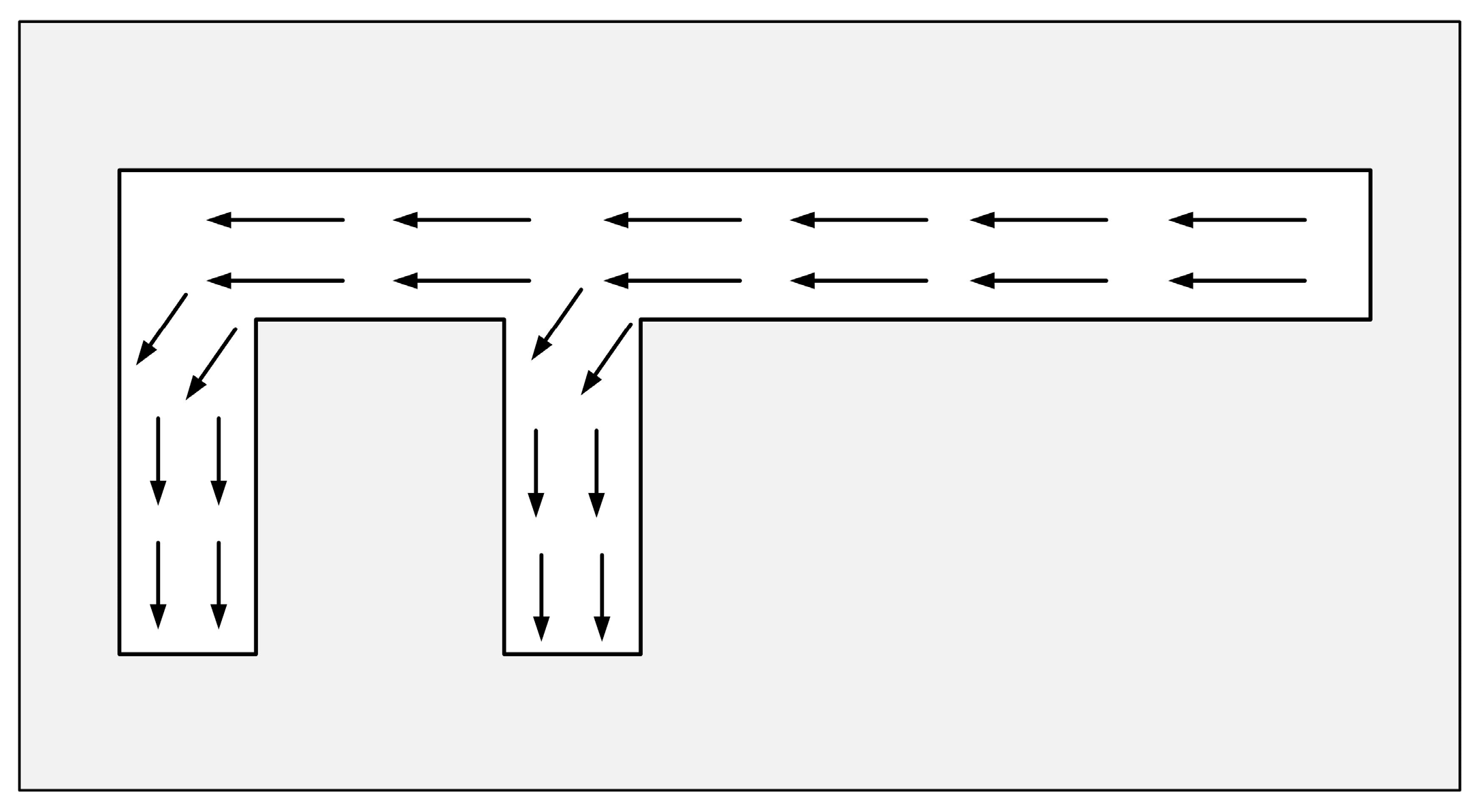
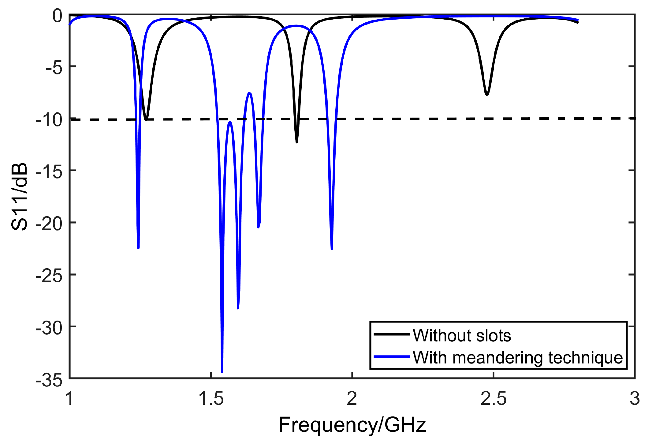
2.1. Meandering Technique
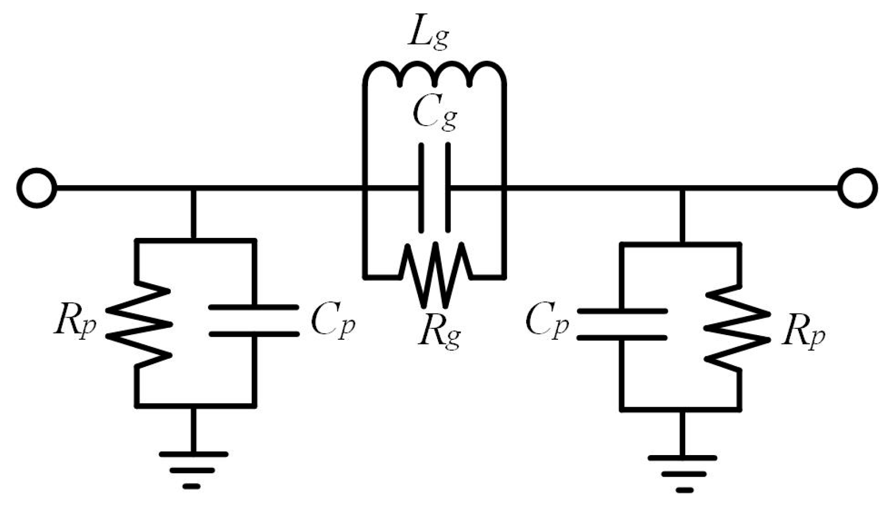
2.2. Defected Ground Structure
3. Antenna Design
3.1. Design Procedure
- Step 1: Determine the basic parameters of the proposed micro-strip antenna patches. The step will be carried out according to the Equations (4)–(8) given in Section 3.4.
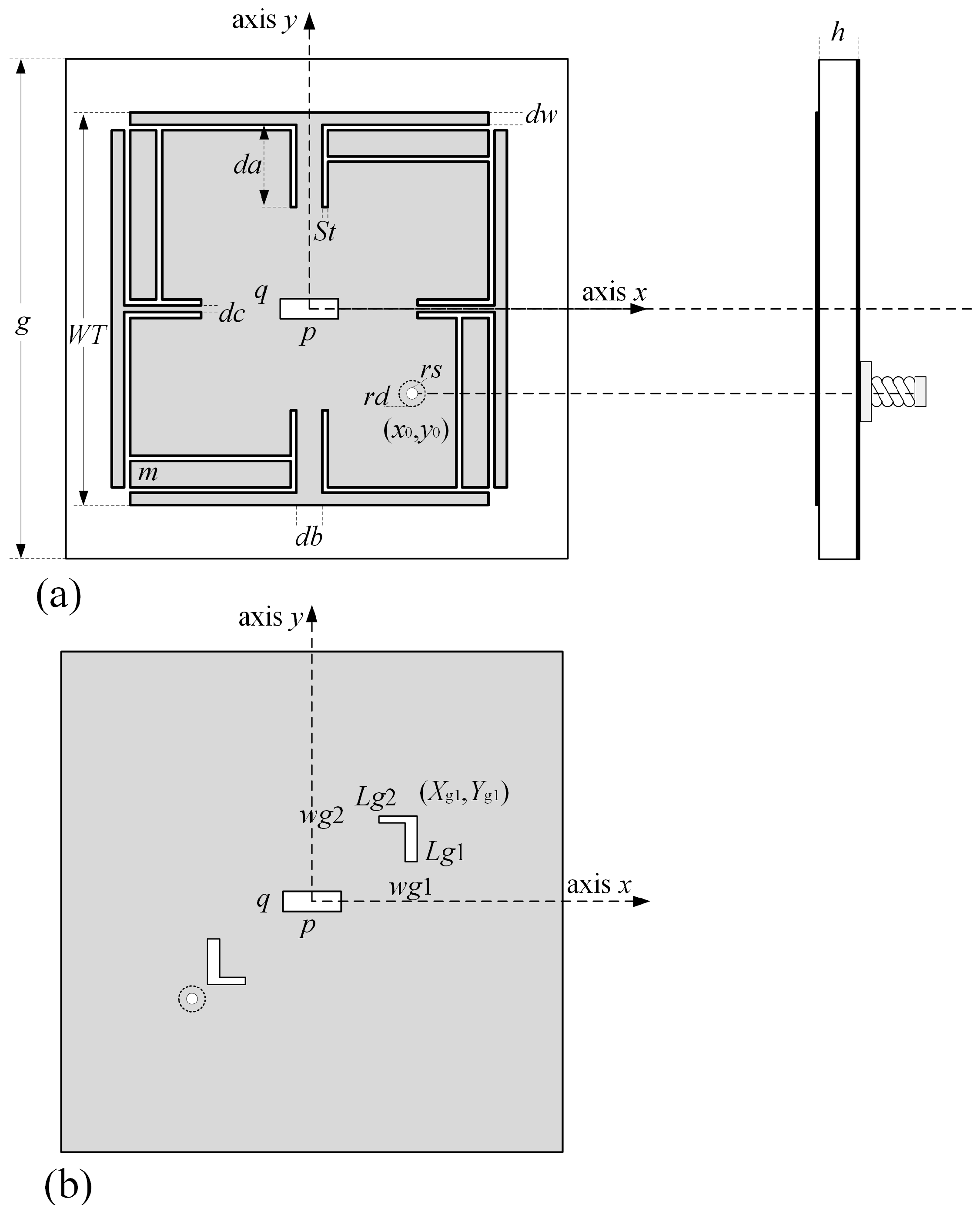
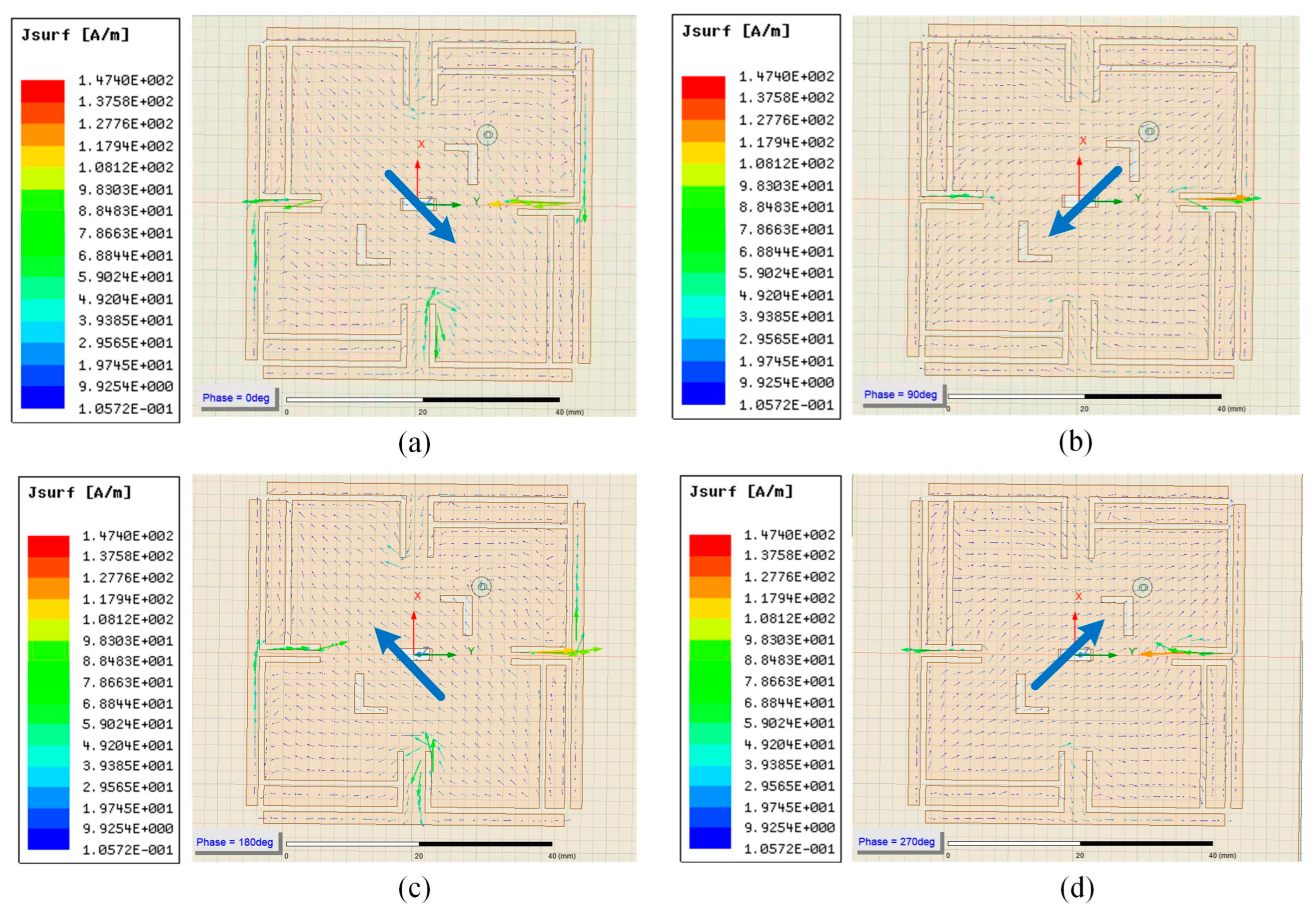
- Step 2: According to the meandering technique, T-shaped and F-shaped gaps are added to adjust the current direction to generate the current that can flow counterclockwise and produce right-handed circularly polarized electromagnetic waves. At the same time, a square gap in the center of the patch is employed to increase the forward gain of the antenna. By means of the gap structure, the enhancement of the surface current path will then reduce the patch size of the antenna.
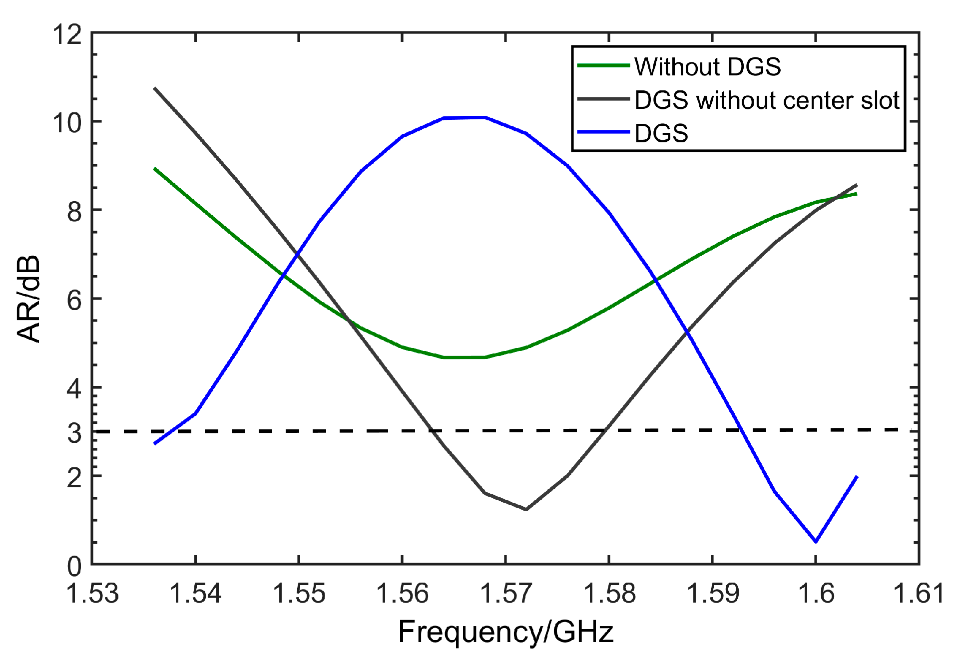
- Step 3: Design a defective structure by introducing two L-shaped slots on the diagonal of the same side of the coaxial feed, aiming at forming a high-impedance surface and expanding the axial bandwidth.
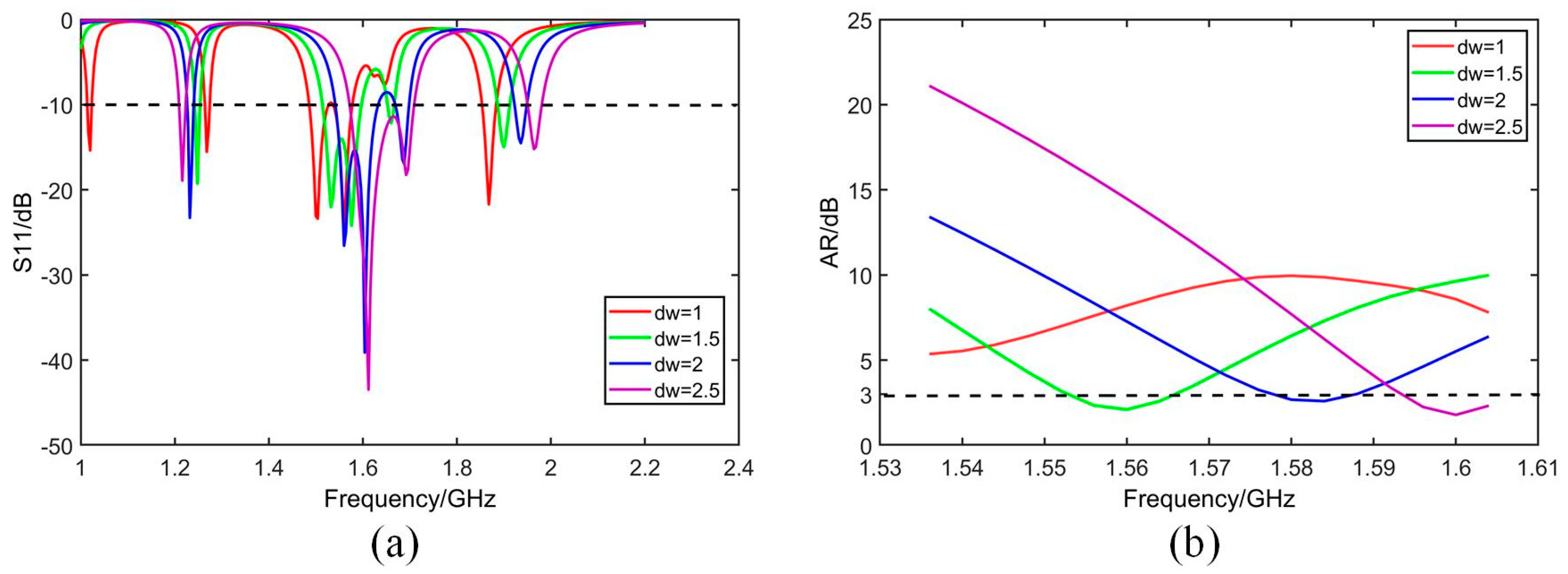
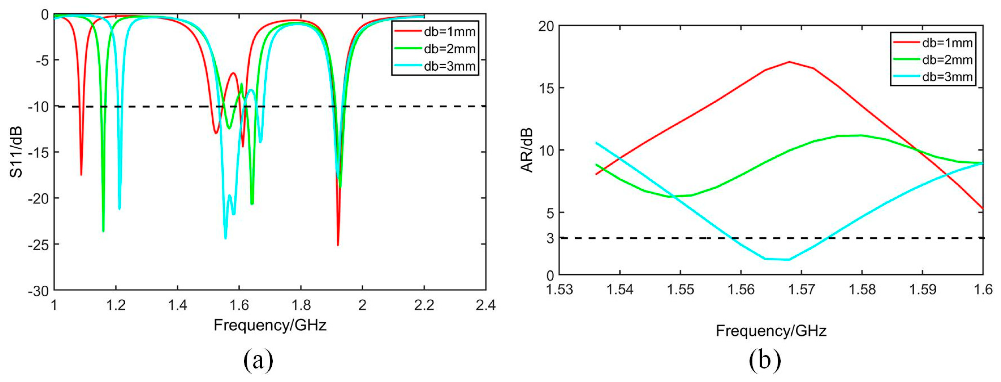
- Step 4: Scan the main parameters that would potentially affect the performance of antenna to determine the size of all antenna parameters.
3.2. Substrate Material
- Step 1: Complete the preliminary design of the patch antenna using the nominal value of FR4 material;
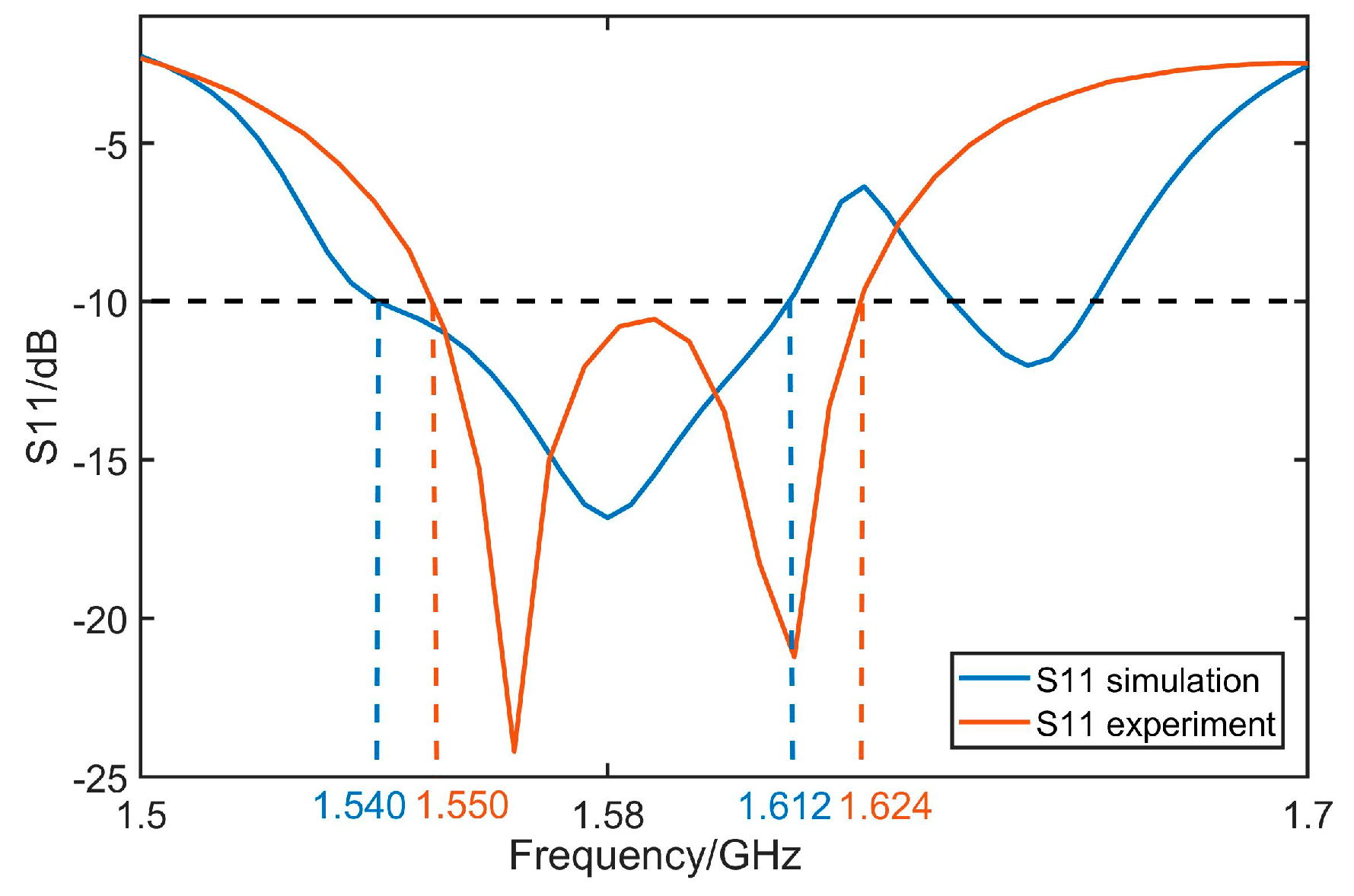
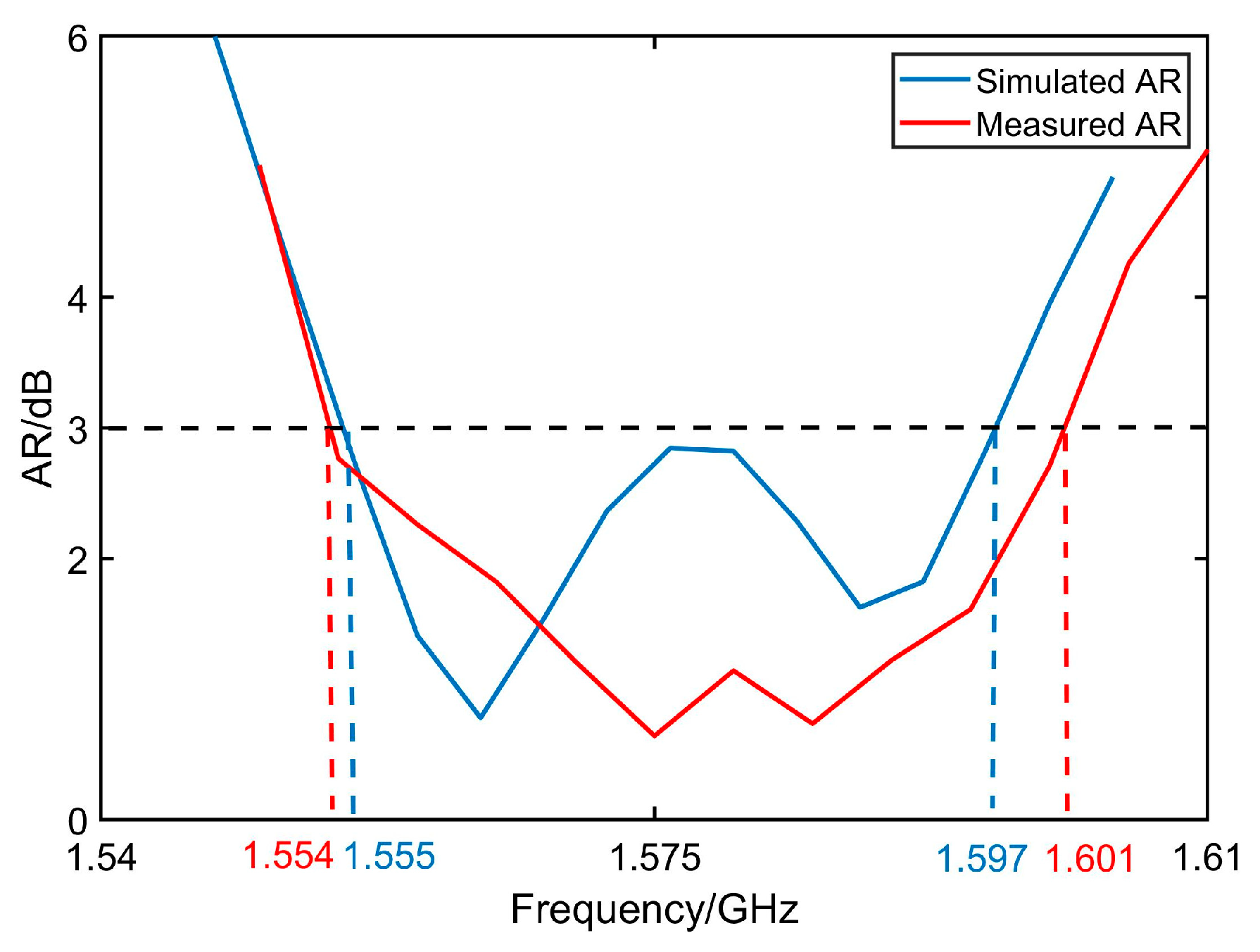
- Step 2: Perform simulations to the designed antenna and extract corresponding S11 and AR distributions, respectively;
- Step 3: Measure the S11 and AR of the designed antenna using vector network analyzer;
- Step 4: Compare the simulation results of the antenna with the measured results to obtain the deviation distribution. Afterward, the values of FR4 in the simulation are adjusted within a certain range to obtain a series of simulated distributions under different values;
- Step 5: Perform least squares analysis on simulated and measured distributions. At this point, the dielectric constant with the smallest least squares estimation value is closest to the true value. In the design of process, permittivity εr of FR4 is calculated and set as 4.52;
- Step 6: Perform antenna design and optimization with the permittivity of FR4 extracted from Step 5.
3.3. Antenna Patch Structure
3.4. Antenna Geometry
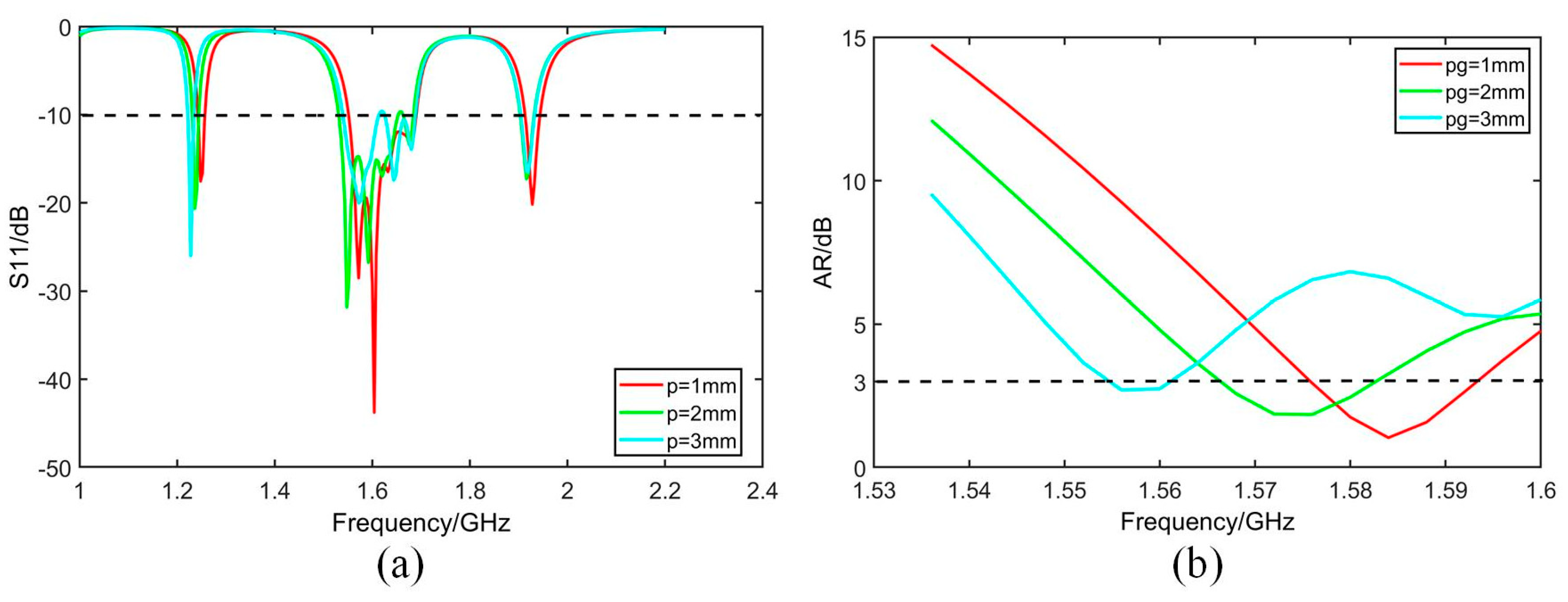
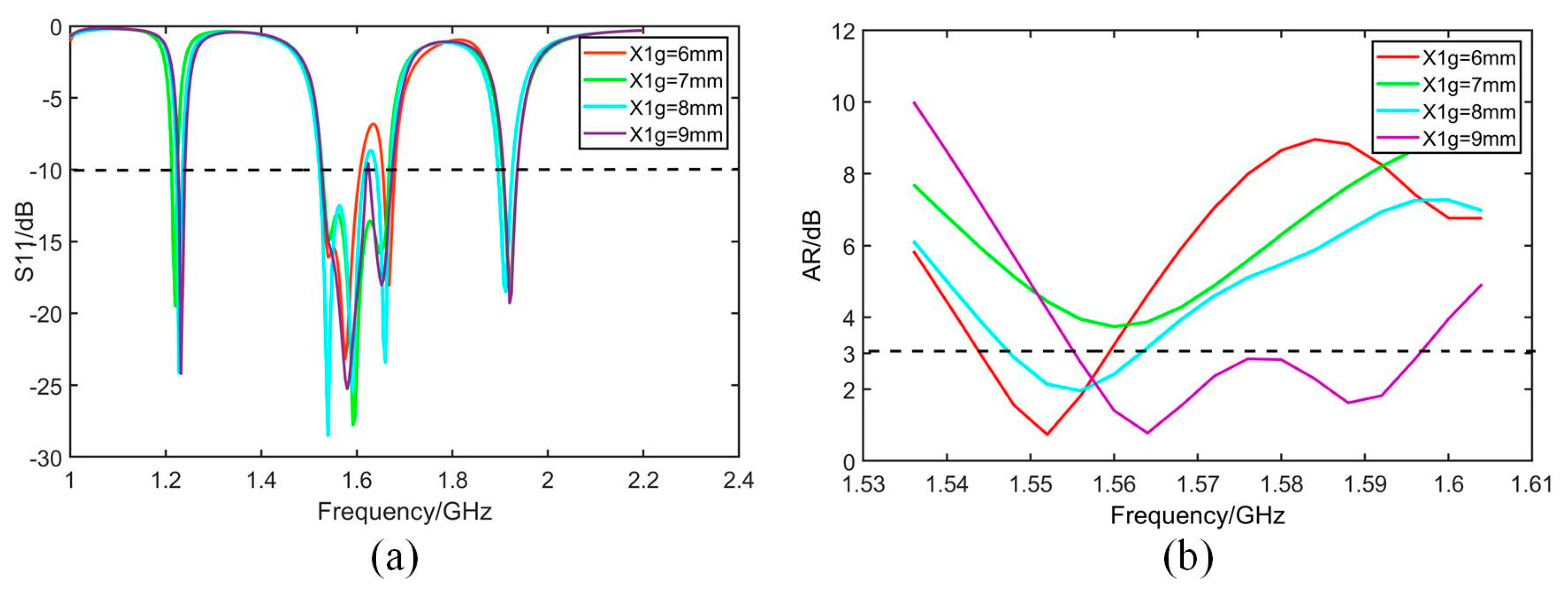
3.5. Parameters Optimization
4. Experiments and Discussions
- (1)
- Since the dielectric substrate material is FR4, its dielectric constant is 4.2 to 4.6, the dielectric constant of FR4 material used by the manufacturer cannot be guaranteed to be identical with the set value of 4.52 in thesofware HFSS (version 19.2). And the dielectric constant of the substrate material has a large effect on the resonant frequency of the antenna, which causes the difference between the simulation and the actual measurement.
- (2)
- In the manufacture of the antenna, high manufacturing accuracy is required due to the use of a loaded seam and defective ground structure. Manufacturing errors within the process allowable errors can also cause errors in the test results of the antenna’s performance.
- (3)
- When welding the coaxial feed probe, the corner of the L-shaped slot of the defective ground structure is inevitably blocked by the SM joint, resulting in a deviation in the measured results.
- (4)
- The unavoidable presence of non-insulating materials in the measurement environment would impact the measurement reliability.
5. Conclusions
Author Contributions
Funding
Data Availability Statement
Acknowledgments
Conflicts of Interest
References
- Dziugiel, B.; Goraj, Z. From statistics, through new requirements to mathematical modelling of SAT aircraft safety. Aircr. Eng. Aerosp. Technol. 2018, 90, 659–666. [Google Scholar] [CrossRef]
- Hwang, S. Terminal-Area Aircraft Tracking Using Hybrid Estimation. J. Guid. Control Dynam. 2009, 32, 836–849. [Google Scholar]
- Wang, L.; Su, J. Robust Disturbance Rejection Control for Attitude Tracking of an Aircraft. IEEE Trans. Control. Syst. Technol. 2015, 23, 2361–2368. [Google Scholar] [CrossRef]
- Han, C.; Yang, Y.; Cai, Z. BeiDou Navigation Satellite System and its Timescales. Metrologia 2011, 48, 213. [Google Scholar] [CrossRef]
- Ashbrook, D.; Starner, T. Using GPS to learn significant locations and predict movement across multiple users. Pers. Ubiquitous Comput. 2003, 7, 275–286. [Google Scholar] [CrossRef]
- Bomemann, W. Navigation satellite system Galileo. Acta Astronaut. 2004, 54, 821–823. [Google Scholar] [CrossRef]
- Wanninger, L. Carrier-phase inter-frequency biases of GLONASS receivers. J. Geodesy 2012, 86, 139–148. [Google Scholar] [CrossRef]
- Tsuji, H.; Orikasa, T.; Toyoshima, M.; Miura, A. On-board Ka-band satellite tracking antenna for unmanned aircraft system. In Proceedings of the 2014 International Symposium on Antennas and Propagation Conference Proceedings, Kaohsiung, Taiwan, 2–5 December 2014; pp. 283–284. [Google Scholar]
- Liu, X.; Liu, G.; Li, Q.; Luo, H. Navigation solution of multi-antennas BDS receivers for measuring the trajectory of space spinning vehicles. In Proceedings of the IEEE Chinese Guidance, Navigation and Control Conference, Yantai, China, 8–10 August 2014; pp. 61–65. [Google Scholar]
- BeiDou Navigation Satellite System (BDS). Airborne Equipment for Aircraft Tracking Only (CTSO-2C604a); Civil Aviation Administration of China: Beijing, China, 2022.
- Li, W.; Gao, S.; Cai, Y.; Luo, Q.; Sobhy, M.; Wei, G.; Xu, J.; Li, J.; Wu, C.; Cheng, Z. Polarization-Reconfigurable Circularly Polarized Planar Antenna Using Switchable Polarizer. IEEE Trans. Antennas Propag. 2017, 65, 4470–4477. [Google Scholar] [CrossRef]
- Yan, Y.; Jiao, Y.; Cheng, H.; Zhang, C. A Low-Profile Dual-Circularly Polarized Wide-Axial-Ratio-Beamwidth Slot Patch Antenna With Six-Port Feeding Network. IEEE Antennas Wirel. Propag. Lett. 2021, 20, 2486–2490. [Google Scholar] [CrossRef]
- Zhong, S.; Sun, Z.; Kong, L.; Gao, C.; Wang, W.; Jin, M. Tri-band dual-polarization shared-aperture microstrip array for SAR applications. IEEE Trans. Antennas Propag. 2012, 60, 4157–4165. [Google Scholar] [CrossRef]
- Wang, X.; Yang, G. Dual frequency and dual circular polarization slot antenna for BeiDou navigation satellite system applications. Microw. Opt. Technol. Lett. 2014, 56, 2222–2225. [Google Scholar] [CrossRef]
- Choi, W.; Kwon, S.; Lee, B. Ceramic chip antenna using meander conductor lines. Electron. Lett. 2001, 37, 933–934. [Google Scholar] [CrossRef]
- Marrocco, G. The art of UHF RFID antenna design: Impedance-matching and size-reduction techniques. IEEE Trans. Antennas Propag. Mag. 2008, 50, 66–79. [Google Scholar] [CrossRef]
- And, K.; Hsieh, G. Broadband circularly polarized microstrip antenna with a chip-resistor loading. Microw. Opt. Technol. Lett. 1998, 19, 1098–2760. [Google Scholar]
- You, C.; Hwang, W. Design of load-bearing antenna structures by embedding technology of microstrip antenna in composite sandwich structure. Compos. Struct. 2005, 71, 378–382. [Google Scholar] [CrossRef]
- Cao, W.; Zhang, B.; Yu, T.; Liu, A.; Guo, D.; Qian, Z. A Compact and broadband chip-resistor loaded circularly polarized microstrip antenna. Frequenz 2011, 65, 131–136. [Google Scholar] [CrossRef]
- Wang, D.; Li, P. A dual-band stacked-patch satellite antenna with parasitic elements for axial ratio beamwidth enhancement. In Proceedings of the 2016 IEEE International Conference on Ubiquitous Wireless Broadband (ICUWB), Nanjing, China, 16–19 October 2016; Volume 79904, p. 7990486. [Google Scholar]
- Zhang, X.; Zhu, L.; Liu, E. Pin-loaded circularly-polarized patch antennas with wide 3-dB axial ratio beam width. IEEE Trans. Antennas Propag. 2017, 65, 521–528. [Google Scholar] [CrossRef]
- Sun, C.; Zheng, H.; Zhang, L.; Liu, Y. Analysis and design of a novel coupled shorting strip for compact patch antenna with bandwidth enhancement. IEEE Antennas Wirel. Lett. 2018, 13, 1477–1481. [Google Scholar]
- Su, C.; Lu, C.; Yin, X. A broadband circular polarized hexagon patch antenna with three feeds. In Proceedings of the Aisa-Pacific Microwave Conference, Kyoto, Japan, 6–9 November 2019; pp. 1169–1171. [Google Scholar]
- Zhang, R.; Huang, J.; Ding, J.; Zhai, G. Compact broadband circularly polarized microstrip antenna with a cross-slotted ground plane. In Proceedings of the IEEE International Symposium on Antennas and Propagation and USNC-URSI Radio Science Meeting, Atlanta, GA, USA, 7–12 July 2019; pp. 1753–1754. [Google Scholar]
- Wei, J.; Jiang, X.; Peng, L. Ultra wideband and high gain circularly polarized antenna with double Y-shape slot. IEEE Trans. Antennas Propag. 2017, 16, 1508–1511. [Google Scholar] [CrossRef]
- Hao, J.; Zhou, Z.; Chan, C. An effective-medium model for high-impedance surfaces. Appl. Phys. A 2007, 87, 281–284. [Google Scholar] [CrossRef]
- Prabhakar, H.; Kummuri, U.; Yadahalli, R.; Munnappa, V. Effect of various meandering slots in rectangular microstrip antenna ground plane for compact broadband operation. Electron. Lett. 2007, 43, 848–850. [Google Scholar] [CrossRef]
- Park, J.; Kim, J.; Kim, C.; Park, J.S.; Qian, Y.; Ahn, D.; Itoh, T. Modeling of a photonic bandgap and its application for the low-pass filter design. In Proceedings of the 1999 Asia Pacific Microwave Conference APMC’99, Singapore, 30 November–3 December 1999; Volume 2, pp. 331–334. [Google Scholar]
- Si, Q.; Zeng, Q.S.; Shi, Y.; Zhang, Y.D. A dual-circle Microstrip array antenna with low Mutual coupling. Modern Radar 2023, 45, 38–45. [Google Scholar]
- Arya, A.K.; Patnaik, A.; Kartikeyan, M.V. Gain Enhancement of Micro-strip patch antenna using Dumbbell shaped Defected Ground Structure. Int. J. Sci. Res. Eng. Technol. 2013, 2, 184–188. [Google Scholar]
- Rais, A.; Azremi, A.A.; Thennarasan, A.; Fong, M.; Hidayath, M.; Ping, J. Miniatured ring slotted circular patch CNSS antenna. In Proceedings of the Asia-Pacific Conference on Applied Electromagnetics, Penang, Malaysia, 20–22 December 2021. [Google Scholar]
- Masaru, H.; Shota, S.; Hitoshi, S. An annular patch circularly polarized antenna in 920-MHz band. In Proceedings of the IEEE International Symposium on Antennas and Propagation, Osaka, Japan, 25–28 January 2020. [Google Scholar]
- Wei, K.; Zhang, Z.; Feng, Z. New Coplanar Capacitively Coupled Feeding Method for Circularly Polarized Patch Antenna. In Proceedings of the IEEE International Symposium on Antennas and Propagation, Spokane, WA, USA, 3–8 July 2021. [Google Scholar]
- Nasimuddin Chen, Z.; Qing, Z. Slotted Microstrip Antennas for Circular Polarization with Compact Size. IEEE Trans. Antennas Propag. 2013, 55, 124–137. [Google Scholar] [CrossRef]
- Ang, M.; Nasimuddin Karim, M.F.; Bin, L.; Chin, F.; Ong, M. A Proximity-coupled Circularly Polarized Slotted-Circular Patch Antenna for RF Energy Harvesting Applications. In Proceedings of the IEEE Region 10 Conference, Singapore, 22–25 November 2016. [Google Scholar]


| Index | Variable | Value/mm | Index | Variable | Value/mm |
|---|---|---|---|---|---|
| 1 | WT | 51.8 | 13 | x0 | 10.4 |
| 2 | g | 70 | 14 | y0 | −10.4 |
| 3 | h | 2 | 15 | Xg1 | 9 |
| 4 | da | 9.38 | 16 | Yg1 | 9 |
| 5 | db | 3.4 | 17 | qg | 5 |
| 6 | dc | 1 | 18 | pg | 1.8 |
| 7 | m | 3.9 | 19 | Lg1 | 6 |
| 8 | St | 0.9 | 20 | Wg1 | 1.4 |
| 9 | dw | 1.8 | 21 | Lg2 | 5 |
| 10 | p | 1.8 | 22 | Wg2 | 1 |
| 11 | q | 5 | 23 | rd | 1.5 |
| 12 | rs | 0.5 |
| Designed Antenna | Size of Antenna | Center Resonant Frequency | Bandwidth of S11 | Bandwidth of AR | Relative Bandwidth |
|---|---|---|---|---|---|
| Reference [31] | 62 mm × 66 mm × 3.2 mm | 1575 MHz | 11.8 MHz | 9.135 MHz | 0.58% |
| Reference [32] | 100 mm × 150 mm × 4 mm | 920 MHz | 50 MHz | 15 MHz | 1.63% |
| Reference [33] | 60 mm × 60 mm × 3 mm | 2250 MHz | 120 MHz | 26 MHz | 1.15% |
| Reference [34] | 90 mm × 90 mm × 1.6 mm | 907 MHz | 18 MHz | 6 MHz | 0.66% |
| Reference [35] | 60 mm × 60 mm × 3.1 mm | 2380 MHz | 137 MHz | 40 MHz | 1.68% |
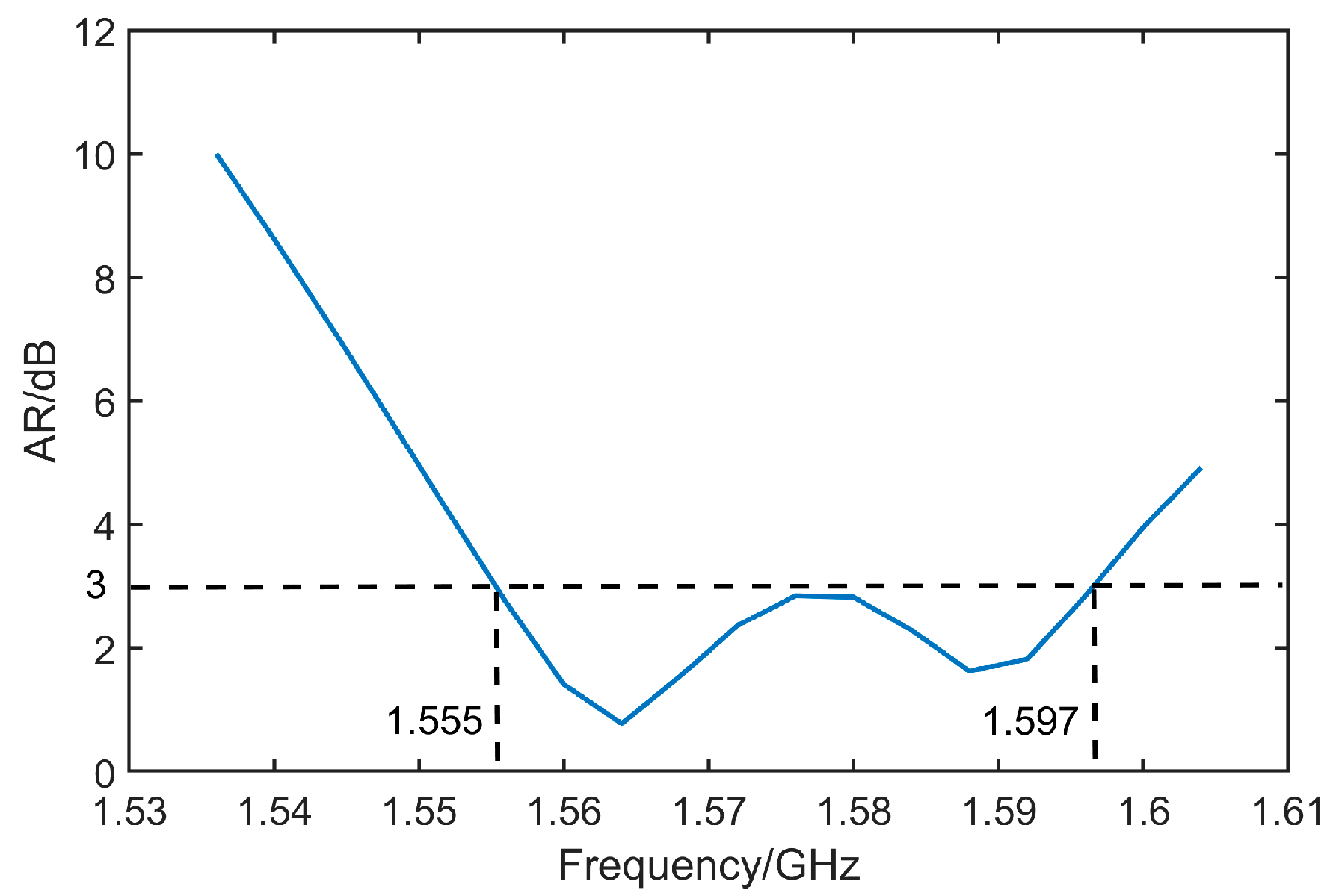
| Proposed antenna | 70 mm × 70 mm × 2 mm | 1575 MHz | 72 MHz | 47 MHz | 2.98% |
Disclaimer/Publisher’s Note: The statements, opinions and data contained in all publications are solely those of the individual author(s) and contributor(s) and not of MDPI and/or the editor(s). MDPI and/or the editor(s) disclaim responsibility for any injury to people or property resulting from any ideas, methods, instructions or products referred to in the content. |
© 2023 by the authors. Licensee MDPI, Basel, Switzerland. This article is an open access article distributed under the terms and conditions of the Creative Commons Attribution (CC BY) license (https://creativecommons.org/licenses/by/4.0/).
Share and Cite
Ma, Z.; Huang, X. Design of a Circularly Polarized Micro-Strip Antenna for Aircraft Tracking Based on BeiDou III Compatible with Multi-Navigation System. Micromachines 2023, 14, 2083. https://doi.org/10.3390/mi14112083
Ma Z, Huang X. Design of a Circularly Polarized Micro-Strip Antenna for Aircraft Tracking Based on BeiDou III Compatible with Multi-Navigation System. Micromachines. 2023; 14(11):2083. https://doi.org/10.3390/mi14112083
Chicago/Turabian StyleMa, Zhenyang, and Xinyi Huang. 2023. "Design of a Circularly Polarized Micro-Strip Antenna for Aircraft Tracking Based on BeiDou III Compatible with Multi-Navigation System" Micromachines 14, no. 11: 2083. https://doi.org/10.3390/mi14112083
APA StyleMa, Z., & Huang, X. (2023). Design of a Circularly Polarized Micro-Strip Antenna for Aircraft Tracking Based on BeiDou III Compatible with Multi-Navigation System. Micromachines, 14(11), 2083. https://doi.org/10.3390/mi14112083