Abstract
In this paper, Silvaco TCAD software is used to simulate the buffer traps in AlGaN/GaN high electron mobility transistors (HEMTs), and its effects on the breakdown performance and key parameters of the devices are investigated by changing the position and concentration of the acceptor traps in the buffer layer. The results show that with the increase of trap concentration, the traps capture electrons and reduce the off-state leakage current, which can improve breakdown voltage of the devices. At the same time, as the trap concentration increases, the ionized traps make a high additional electric field near the drain edge, leading to the decrease of breakdown voltage. With the combined two effects above, the breakdown voltage almost ultimately saturates. When the source-to-gate (Access-S) region in the GaN buffer layer is doped alone, the minimum and most linear leakage current for the same trap concentrations are obtained, and the additional electric field has a relatively small effect on the electric field peak near the drain as the ionized traps are furthest from drain. All these factors make the breakdown voltage increase more controllably with the Access-S region doping, and it is a more potential way to improve the breakdown performance.
1. Introduction
The AlGaN/GaN high electron mobility transistors (HEMTs) are considered to be promising candidates for the next generation of high power and high frequency devices, due to their outstanding combination of fundamental physical properties, such as large breakdown fields, high two-dimensional electron gas (2DEG) density, low on-state resistance, and high electron mobility [1,2]. In recent years, GaN power electronic devices have received wide attention in microwave and power applications [3,4]. However, under the standard growth conditions, n-type background carriers are introduced within the GaN buffer layer, leading to an increase of leakage current, which in turn leads to poor breakdown performance of the devices. Breakdown voltage of the devices determines the maximum operating voltage and output power [5]. Therefore, in order to achieve a semi-insulating GaN buffer layer, compensation doping in the GaN buffer layer is a common technique. Through density functional theory-based calculations, it is shown that C (or Fe) has a higher probability to replace N due to lower formation energy required for C-N (or C-Fe) substitution in the GaN buffer layer [6]. As a result, the injection of impurities (Fe, C, etc.) into the GaN buffer layer are often used in the manufacturing process to form acceptor traps with deep energy levels [7]. Therefore, the acceptor traps can capture the background electrons to achieve the high resistance characteristic of the buffer layer and reduce the undesirable effect of buffer leakage currents [8]. The effects of the doping concentration in the buffer layer on the DC as well as frequency characteristics of the devices have been studied extensively [8,9]. However, the trend and mechanism of the doping concentration effect on delaying the avalanche breakdown and increasing the breakdown voltage of the devices are not clear. Bahat-Treidel et al. propose that the subthreshold buffer leakage currents are reduced and thus, postpone Vbd (breakdown voltage) to higher voltages by doping in the buffer layer [10]. Zhu et al. believe that with gate-to-drain spacing increasing, the negatively charged buffer traps region spreads wider and the depletion region length becomes longer, playing a key role in the linear dependence of off-state breakdown voltage on gate to drain spacing [11]. Joshi et al. propose that there is an optimum moderate buffer acceptor trap concentration for maximizing the breakdown voltage as a function of gate–drain distance and field plate length [12], but the mechanism of acceptor trap action in the buffer layer is not described. Therefore, it is important to study the influence of the acceptor trap concentration on the breakdown voltage of the AlGaN/GaN HEMTs. Also, selecting a reasonable doping concentration for the reduction of the leakage current and the improvement of breakdown voltage is very beneficial to improve the device performances. In this paper, we investigated the effects of the acceptor trap concentration in the GaN buffer layer on the leakage current and breakdown performance of conventional depletion-mode (D-mode) AlGaN/GaN HEMTs by using Silvaco TCAD software [13]. Furthermore, the physical mechanism and degradation trend were analyzed by combining the device electric field and electrons concentration distribution with simulation plots; the key region affecting the breakdown performance of AlGaN/GaN HEMTs was proposed to provide a theoretical basis for optimizing the breakdown performance of the devices.
2. Computational Framework
Based on the reference [14] and the actual manufacturing process, device cross section as shown in Figure 1 is used for computations in this paper. The materials from bottom to top are sapphire substrate, 1 μm GaN buffer layer, 20 nm AlGaN barrier layer with Al component of 0.3, and Si3N4 passivation material with 60 nm thickness, respectively. In addition, the gate width of the device is 50 μm. A background carrier concentration of 1 × 1015 cm−3 is added to the GaN buffer layer. The device has Ohmic contacts at the drain and source electrodes. The gate electrode is a Schottky contact; a barrier height of 1.6 eV is considered [15].
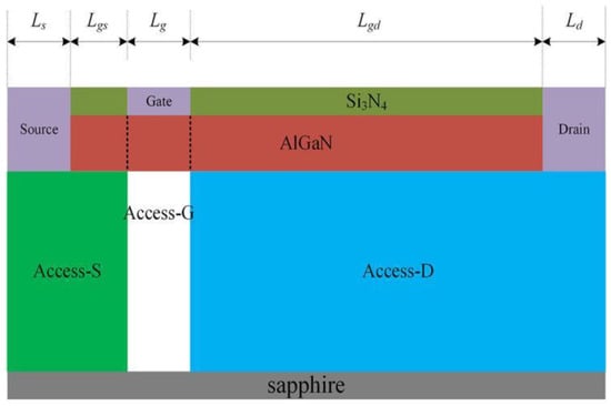
Figure 1.
Simulation structure and buffer layer area division.
The distance (Lgs) of source to gate and the distance (Lgd) of gate to drain are 1 μm and 4 μm, respectively, and the length of gate (Lg), drain (Ld), and source (Ls) electrodes are all 1 μm. The one-dimensional Schrodinger equation is applied to obtain two-dimensional electron gas (2DEG) in the AlGaN/GaN heterostructure [16]. The Shockley–Read–Hall (SRH) recombination model is used to simulate the charging and discharging effect of the acceptor traps. To simulate carrier mobility changes in practice, the doping-dependent mobility model and high-field saturation model are used to calculate the electron mobility, including the low-field mobility model (Albrct.n) and high-field mobility model (Gansat) [17,18]. A fixed temperature of T = 300 K is assumed in simulation because a self-heating effect could be neglected due to off-state working conditions of devices. Furthermore, the Selberherr’s impact ionization model is used in the paper to simulate the breakdown of the buffer layer caused by impact ionization. The material parameters of AlGaN, such as work function, bandgap, and dielectric coefficient, are obtained by linear interpolation between GaN and AlN [6]. In addition, we define the source-to-gate region in the buffer layer as the Access-S (green area in Figure 1), the region below the gate as the Access-G (white area in Figure 1), and the gate-to-drain region in the buffer layer as the Access-D region (blue area in Figure 1). To ensure consistency with the actual manufacturing process, the source and drain electrodes are all etched into the GaN buffer layer in simulation to be able to directly contact the heterojunction channel [19]. Meanwhile, the parameters of the GaN material are set in simulation as shown in Table 1 [20,21].

Table 1.
The parameters of GaN material in simulation.
When the device is in the off-state, there are two general methods for determining breakdown voltage (Vbd): one is defined as the drain voltage corresponding to a drain current of 1 mA/mm [22]; the other is defined as the drain voltage corresponding to a sharp rise in the drain current [23], which is also the way to determine the occurrence of breakdown in this paper. To ensure that the trap parameters in the buffer layer are consistent with the trap introduced by the actual doping, only the acceptor traps are added to the buffer layer. The trap energy level and capture cross section are Ec −0.5 eV and 1 × 10⁻¹⁵ cm−2, respectively [24,25]. As the GaN buffer layer doping process introduces the acceptor trap concentration in the range of 1015 cm−3 to 1018 cm−3 in the actual process [26,27], we define that the concentration of the acceptor traps varies from 1 × 1015 cm−3 to 1 × 1018 cm−3 in each region. The transfer and transconductance curves of the device are shown in Figure 2a. Transductance is the differential of the drain current (Id) to the gate voltage (Vg), reflecting the ability of the gate electrode to control the drain current. The threshold voltage obtained from the transfer curve is −2.465 V and the maximum transconductance is 334.3 mS/mm, which meet the simulation requirements for depletion-mode devices [7,26]. The variation of threshold voltage with acceptor trap concentrations is shown in Figure 2b; it can be seen that the threshold voltage increases with the increase of trap concentration, which is consistent with others’ research [9,12,27]. Therefore, the structure can be used as the simulation of breakdown performance.
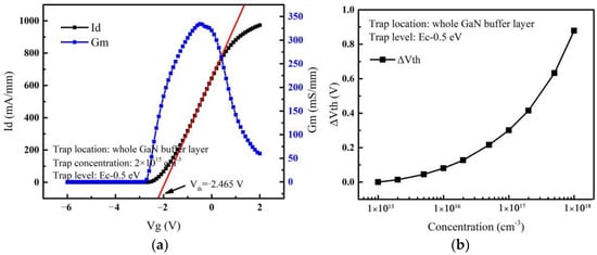
Figure 2.
(a) Transfer and transconductance curves. (b) The variation of threshold voltage with acceptor trap concentrations.
The off-state gate voltage is set to –6 V in the simulation of breakdown performance. When the device is in the off-state, some unexpected electrons will still flow to the drain electrode, and the drain current will increase with the increase of drain voltage. When the device breaks down, the drain current will rise sharply. Therefore, when the device is in the off-state, we call the leakage drain current in the breakdown curve as the off-state leakage current. We define Id-leak (the parameter of leakage current) as the drain current, corresponding to Vd = Vbd/2 in the breakdown curve [27], and the expression is shown below.
3. Effect of Traps in the Whole Buffer Layer
The breakdown voltage and leakage current of the device with the acceptor traps introduced in the whole buffer layer are shown in Figure 3a. It can be observed that when the acceptor trap energy level is fixed, the breakdown voltage (Vbd) increases and gradually saturates with the increase of trap concentration. Its maximum value exists around 5 × 1016 cm−3 and then starts to decrease slightly with the trap concentration increasing. Figure 3b shows the electric field distribution at 1 nm below the heterojunction channel when the device breaks down. As the concentration of acceptor traps in the GaN buffer layer increases, the electric field near the gate is almost unchanged, while it is more variable near the drain edge. This means that the change in the concentration of the traps mainly affects the electric field peak near the drain edge, which in turn affects the variation of breakdown voltage. The breakdown location of AlGaN/GaN HEMTs tends to occur at the electric field peak [28].
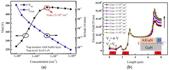
Figure 3.
(a) Effect of acceptor trap concentration in the whole buffer layer on Vbd and Id-leak. (b) Electric fields extracted along the lateral line (C-C’) at the onset of avalanche breakdown for different acceptor trap concentrations. Inset: cut-line along which electric fields are extracted.
It can be seen from Figure 3a that the leakage current (Id-leak) decreases continuously with the increase of trap concentration. At the same time, the breakdown voltage continues to increase until the acceptor trap concentration reaches 5 × 1016 cm−3. Under the condition of considering that only electrons capture effect, the SRH capture rate () can be expressed as [29,30]:
where p is the concentration of acceptor traps, τp is the lifetime of hole, NC is the effective density of states for electrons, ni is the intrinsic electron concentration, Etrap is the difference between the trap energy level and the intrinsic Fermi level, EFn is the electron quasi-Fermi energy, Ec is the conduction band energy, k is Boltzman’s constant, T is the lattice temperature.
From Equations (2) and (3), it can be seen that when the acceptor trap energy is fixed (i.e., Etrap is fixed), the electrons’ capture rate increases with the increase of acceptor trap concentration p and parameter ηn, and the parameter ηn is proportional to the difference between the conduction band energy (Ec) and the Fermi energy (EFn). Figure 4a shows the conduction band energy of the device at different trap concentrations; it can be seen that the Fermi energy (EFn) is closer to the conduction band (Ec) when the acceptor trap concentration is lower. That is, ηn is smaller when the trap concentration is lower. In other words, the number of electrons captured by acceptor traps will increase with the high trap concentration, which in turn leads to a decrease in the leakage current in the buffer layer. With the decrease of the leakage current, the resistivity of the buffer layer gradually increases, thus delaying its avalanche breakdown [9,31]. Therefore, the breakdown voltage continues to increase until the trap concentration reaches 5 × 1016 cm−3.
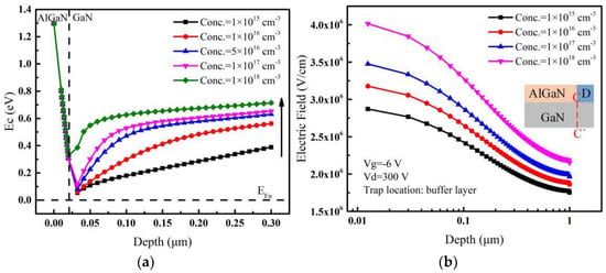
Figure 4.
For different acceptor trap concentrations, (a) conduction band energy extracted along a vertical line (at the center of the gate electrode) traversing from AlGaN surface (0 nm) to GaN buffer layer. (b) Electric fields extracted along the vertical line (C-C’) near the drain edge when the drain voltage is 300 V. Inset: cut-line along which electric fields are extracted.
As the acceptor trap concentration increases, the leakage current continues to decrease. However, when the acceptor trap concentration exceeds 5 × 1016 cm−3, the breakdown voltage no longer continues to increase as the leakage current decreases, but reaches saturation and even decreases slightly as shown in Figure 3a. This is mainly due to the formation of negative charges (ionized traps) after trapping electrons [32]. The trapping electrons can create an additional built-in electric field whose direction is the same to that applied by the drain voltage [27], and then the whole electric field is strengthened. Therefore, when the drain voltage is fixed, the difference of electric fields with different acceptor trap concentrations in the buffer layer is caused by the additional built-in electric field. As the acceptor traps mainly affect the peak of the electric field near the drain edge (see Figure 3b), the electric fields near the drain edge are extracted along the vertical line (C-C’) and shown in Figure 4b when the drain voltage is fixed at a high value. It can be seen that the electric field near the drain becomes larger with the increase of acceptor trap concentration by the effect of the additional electric field, and the higher the electric field is, the easier the breakdown takes place [28]. Therefore, the additional electric field whose direction is the same to that applied by the drain voltage can make the breakdown voltage decrease.
As discussed above, there are two factors affecting the breakdown voltage. One is that the capture of electrons by the acceptor traps reduces the leakage current and then increases the breakdown voltage of the device. Second is that the ionized traps can generate an additional electric field near the drain edge and the direction is the same to that applied by the drain voltage, resulting in a decrease in the breakdown voltage. Under the combined two effects above, the breakdown voltage almost saturates when the trap concentration increases to 5 × 1016 cm−3 and then decreases slightly as the additional electric field effect becomes a little larger with the trap concentration continuously increases as shown in the Figure 3a.
To further investigate the availability of region doping in the GaN buffer layer, we will analyze the effects of acceptor traps in the Access-D, Access-G, and Access-S regions on the breakdown performance of the device in the following subsections, respectively.
3.1. Effect of Traps in the Access-D Region
When the acceptor traps are only introduced in the Access-D region, the variation of leakage current and breakdown voltage with the acceptor trap concentration are shown in Figure 5a. The breakdown voltage reaches a maximum value by increasing the concentration of traps up to 2 × 1017 cm−3 and then decreases. The leakage current decreases by about 5 orders of magnitude. For different acceptor trap concentrations, electric fields extracted along the vertical line (C-C’) near the drain edge with a high drain voltage are shown in Figure 5b. It shows that the electric field near the drain increases continuously with the increase of the acceptor trap concentration. As a result, when the trap concentration is lower (before 2 × 1016 cm−3), a slight decrease in leakage current occurs, resulting in a little change in breakdown voltage. As the trap concentration continues to increase, the leakage current decreases rapidly, causing a rapid increase in the breakdown voltage. Also, because of the higher acceptor trap concentration, a higher additional electric field is introduced near the drain edge [33]. As the acceptor traps in the Access-D region are closer to the drain electrode, the additional electric field formed by ionized traps has a more obvious effect on the electric field peak near the drain. As discussed above, the breakdown voltage starts to drop after saturation as shown in Figure 5a.
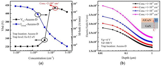
Figure 5.
(a) Impact of acceptor trap concentration considered in the Access-D region on Vbd and Id-leak. (b) For different acceptor trap concentrations, electric fields extracted along the vertical line (C-C’) near the drain edge when the drain voltage is 300 V. Inset: cut-line along which electric fields are extracted.
3.2. Effect of Traps in the Access-G Region
When the acceptor traps are only introduced in the Access-G region, the variation of leakage current and breakdown voltage with the acceptor trap concentration are shown in Figure 6a. It can be seen that the breakdown voltage increases first and then gradually saturates as the trap concentration in the Access-G region increases. The leakage current decreases by about 6 orders of magnitude. When the trap concentration is lower, the leakage current decreases rapidly with the acceptor trap concentration increasing, leading to a rapid increase in the breakdown voltage. For different acceptor trap concentrations, electric fields extracted along the vertical line (C-C’) near the drain edge with a high drain voltage are shown in Figure 6b. It can be seen that with the change of the acceptor trap concentration in the Access-G region, the electric field varies less than that with introducing acceptor traps in the Access-D region. This behavior can be explained as follows.
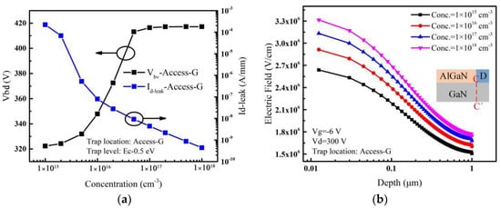
Figure 6.
(a) Impact of acceptor trap concentration considered in the Access-G region on Vbd and Id-leak. (b) For different acceptor trap concentrations, electric fields extracted along the vertical line (C-C’) near the drain edge when the drain voltage is 300 V. Inset: cut-line along which electric fields are extracted.
The distribution of the ionized acceptor traps in the Access-G region is simulated and shown in Figure 7. Ionized traps move down because of the repelling effect of negative gate voltage [32]. Therefore, compared with traps in the Access-D region, the ionized traps in the Access-G region are mainly distributed in the region below the gate and further away from the drain. This results in a relatively small increase of the additional electric field near the drain. Under the combined effect of the decreasing leakage current and the smaller increasing additional electric field near the drain, the breakdown voltage saturates at last (see Figure 6a).
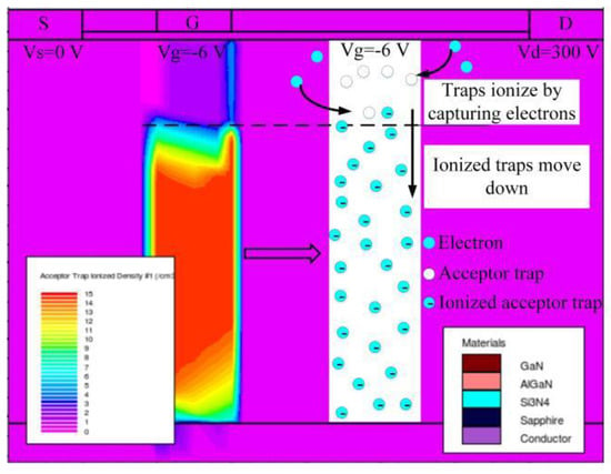
Figure 7.
Ionized acceptor traps distribution in the Access-G region.
3.3. Effect of Traps in the Access-S Region
When the acceptor traps are only introduced in the Access-S region, the variation of leakage current and breakdown voltage with the acceptor trap concentration are shown in Figure 8a. The breakdown voltage increases rapidly and then slowly with the increase of the acceptor trap concentration in the Access-S region. The leakage current decreases by about 6 orders of magnitude. With the increase of trap concentration in the Access-S region, the leakage current decreases and the breakdown voltage increases. Meanwhile, ionized traps create an additional electric field in the GaN layer. The electric fields extracted along the lateral line (C-C’) near the drain edge are shown in Figure 8b. The result shows that the electric field near the drain edge varies less with trap concentration compared with that in the Access-D and Access-G regions. This means that the additional electric field generated by the ionized traps has the smallest effect on the electric field peak near the drain edge, as the traps in the Access-S region are farthest from the drain electrode. Therefore, with the smallest effect of the additional electric field, the breakdown voltage still increases slowly instead of dropping or saturation at the larger trap concentrations as shown in Figure 8a.
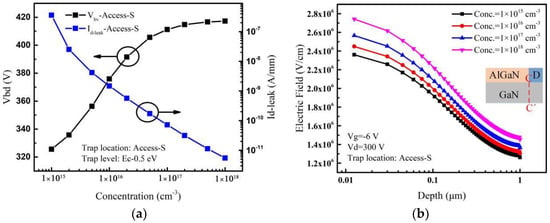
Figure 8.
(a) Effect of acceptor trap concentration in the Access-S region on Vbd and Id-leak. (b) For different acceptor trap concentrations, electric fields extracted along the vertical line (C-C’) near the drain edge when the drain voltage is 300 V. Inset: cut-line along which electric fields are extracted.
3.4. Comparison of Leakage Current When Traps Are Introduced in Different Regions
The simulation results show that the artificial doping concentrations of Fe or C should be strictly controlled to improve the breakdown voltage. In particular, it is important to avoid the deterioration of the breakdown performance due to the high doping concentration [34,35,36].
Figure 9 shows the variations of off-state leakage currents when acceptor traps are introduced in different regions. It can be seen that the traps in the Access-S region cause the minimum leakage current for the same trap concentration. The distribution of electrons inside the device under the off-state gate voltage condition is shown in Figure 10. The flow direction of electrons in the buffer layer is from the source to the drain when the device is at a negative gate voltage and positive drain voltage [37]. Therefore, the electron concentration in the Access-S region is the highest compared with those in the Access-D and Access-G regions as shown in Figure 10, which makes it easier for the acceptor traps in the Access-S region to capture electrons. As a result, for the same trap concentration, the leakage current is relatively small as more electrons are trapped when the traps are located in the Access-S region.
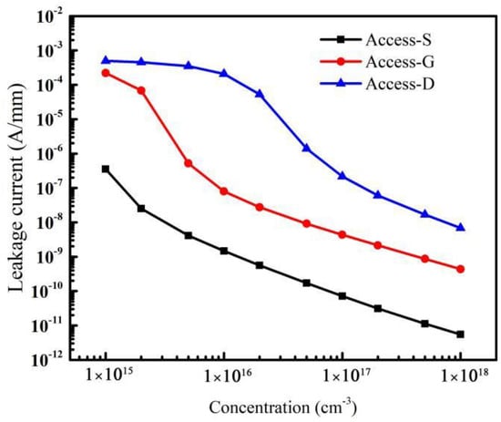
Figure 9.
Variations of leakage current caused by traps in different regions.
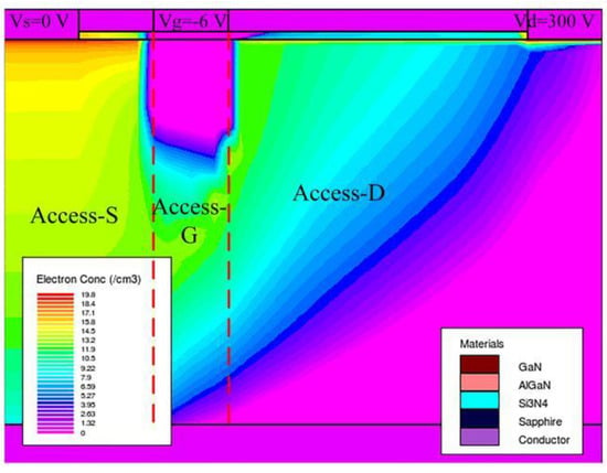
Figure 10.
The distribution of electrons inside the device under the off-state voltage.
In addition, the variation of the leakage current is directly related to the breakdown voltage of the device [38]. The acceptor traps in the Access-S region can obtain a more uniform variation of the leakage current, and the decreasing trend of the leakage current is almost linear (see Figure 9). Thus, the breakdown voltage rises more gently and evenly with doping in the Access-S region. Moreover, because the acceptor traps in the Access-S region are farthest away from the drain, the additional electric field caused by ionized traps has the smallest effect on the electric field peak near the drain. All factors above make the breakdown voltage increase more controllably. Therefore, it is a potential approach to control breakdown voltage by doping in the Access-S region during the fabrication process, though more research and practice are needed before its practical application.
4. Conclusions
This paper focuses on the effect of the concentration and distribution of the acceptor traps in the buffer layer on breakdown performance of the AlGaN/GaN HEMTs. The results show that the acceptor traps can capture electrons generated by ionization collisions and then decrease off-state leakage currents, which result in an increase of the breakdown voltage. At the same time, with the increase of trap concentration, the electric field near the drain will increase as the ionized traps can create an additional built-in electric field whose direction is the same to that applied by the drain voltage. Under the combination of the above two effects, the breakdown voltage almost ultimately saturates even though the leakage current continues to decrease when the traps are introduced in the whole buffer layer. In addition, the effects of traps in the source-to-gate region (Access-S), the region below the gate (Access-G), and the gate-to-drain region (Access-D) on the breakdown performance of the device are studied separately. The results show that the acceptor traps in the Access-S region can cause the minimum and linear leakage current, and the breakdown voltage can be increased more controllably. Therefore, doping in the Access-S region during the fabrication process is a more potential way to improve the breakdown performance of the device than doping in the other two regions.
Author Contributions
Funding acquisition, Y.C.; Methodology, M.M.; Project administration, Y.C.; Resources, Y.C., X.Z. (Xuefeng Zheng) and L.L.; software, M.M., H.L. and Z.W.; Writing—original draft preparation, M.M. and Y.C.; Writing—review and editing, M.M., Y.C., L.W., X.Z. (Xinxiang Zhang), C.C., W.T., X.M. and Y.H. All authors have read and agreed to the published version of the manuscript.
Funding
This research was funded by the National Key R&D Program of China (Grant No. 2022YFB4400400), the National Natural Science Foundation of China (Grant No. 62234013, 11690042, 12035019), the Cooperation Program of XDU-Chongqing IC Innovation Research Institute (Grant No. CQIRI-2022CXY-Y10), the National Major Scientific Research Instrument Projects (Grant No. 61727804) and the Natural Science Foundation of Shaanxi Province (Grant No. 2022-JM-386).
Conflicts of Interest
The authors declare no conflict of interest.
References
- Zhang, Y.; Huang, S.; Wei, K.; Zhang, S.; Wang, X.; Zheng, Y.; Liu, G.; Chen, X.; Li, Y.; Liu, X. Millimeter-Wave AlGaN/GaN HEMTs with 43.6% Power-Added-Efficiency at 40 GHz Fabricated by Atomic Layer Etching Gate Recess. IEEE Electron Device Lett. 2020, 41, 701–704. [Google Scholar] [CrossRef]
- Jarndal, A.; Kompa, G.A. new small-signal modeling approach applied to GaN devices. IEEE Trans. Microw. Theory Tech. 2005, 53, 3440–3448. [Google Scholar] [CrossRef]
- Yadav, Y.K.; Upadhyay, B.B.; Meer, M.; Bhardwaj, N.; Ganguly, S.; Saha, D. Ti/Au/Al/Ni/Au Low Contact Resistance and Sharp Edge Acuity for Highly Scalable AlGaN/GaN HEMTs. IEEE Electron Device Lett. 2019, 40, 67–70. [Google Scholar] [CrossRef]
- Albahrani, S.A.; Heuken, L.; Schwantuschke, D.; Gneiting, T.; Burghartz, J.N.; Khandelwal, S. Consistent Surface-Potential-Based Modeling of Drain and Gate Currents in AlGaN/GaN HEMTs. IEEE Trans. Electron Devices 2020, 67, 455–462. [Google Scholar] [CrossRef]
- Ohno, Y.; Nakao, T.; Kishimoto, S.; Maezawa, K.; Mizutani, T. Effects of surface passivation on breakdown of AlGaN/GaN high-electron-mobility transistor. Appl. Phys. Lett. 2004, 84, 2184–2186. [Google Scholar] [CrossRef]
- Lyons, J.L.; Janotti, A.; Walle, C.G. Effects of carbon on the electrical and optical properties of InN, GaN, and AlN. Phys. Rev. B 2014, 89, 035204. [Google Scholar] [CrossRef]
- Fariza, A.; Lesnik, A.; Bläsing, J.; Hoffmann, M.P.; Horich, F.; Veit, P.; Witte, H.; Dadgar, A.; Strittmater, A. On reduction of current leakage in GaN by carbon-doping. Appl. Phys. Lett. 2016, 109, 212102. [Google Scholar] [CrossRef]
- Uren, M.J.; Caesar, M.; Karboyan, S.; Moens, P.; Vanmeerbeek, p.; Kuball, M. Electric field reduction in C-doped AlGaN/GaN on Si high electron mobility transistors. IEEE Electron Device Lett. 2015, 36, 826–828. [Google Scholar] [CrossRef]
- Uren, M.J.; Moreke, J.; Kuball, M. Buffer design to minimize current collapse in GaN/AlGaN HFETs. IEEE Trans. Electron Devices 2012, 59, 3327–3333. [Google Scholar] [CrossRef]
- Bahat-Treidel, E.; Brunner, F.; Hilt, O.; Cho, E.; Wurfl, J.; Trankle, G. AlGaN/GaN/GaN: C Back-Barrier HFETs With Breakdown Voltage of Over 1 kV and Low RON × A. IEEE Trans. Electron Devices 2010, 57, 3050–3058. [Google Scholar] [CrossRef]
- Zhu, L.; Wang, J.; Jiang, H.; Wang, H.; Wu, W.; Zhou, Y.; Dai, G. Theoretical analysis of buffer trapping effects on off-state breakdown between gate and drain in AlGaN/GaN HEMTs. In Proceedings of the 2016 International Conference on Integrated Circuits and Microsystems (ICICM), Chengdu, China, 23–25 November 2016; pp. 33–36. [Google Scholar]
- Joshi, V.; Gupta, S.D.; Chaudhuri, R.R.; Shrivastava, M. Interplay between surface and buffer traps in governing breakdown characteristics of AlGaN/GaN HEMTs—Part II. IEEE Trans. Electron Devices 2020, 68, 80–87. [Google Scholar] [CrossRef]
- Silvaco Inc. ATLAS Device Simulation Software; Silvaco Inc.: Santa Clara, CA, USA, 2022. [Google Scholar]
- Pattnaik, G.; Mohapatra, M. Comparison Of DC & RF Characteristics of AlGaN/GaN HEMT Using Different Surface Passivation Materials. In Proceedings of the 2021 IEEE 2nd International Conference on Applied Electromagnetics, Signal Processing, & Communication (AESPC), Bhubaneswar, India, 26–28 November 2021; pp. 1–5. [Google Scholar]
- Miccoli, C.; Cerantonio, V.; Chini, A.; Iucolano, F. T-CAD simulations study on drain leakage current and its correlation with gate current for AlGaN/GaN HEMTs. In Proceedings of the IEEE 8th Workshop on Wide Bandgap Power Devices and Applications (WiPDA), Redondo Beach, CA, USA, 7–9 November 2021; pp. 255–258. [Google Scholar]
- Tang, N.; Shen, B.; Zheng, Z.W.; Liu, J.; Chen, D.J.; Lu, J.; Zhang, R.; Shi, Y.; Zheng, Y.D. Magnetoresistance oscillations induced by intersubband scattering of two-dimensional electron gas in Al0.22Ga0.78N/GaN heterostructures. J. Appl. Phys. 2003, 94, 5420–5422. [Google Scholar] [CrossRef]
- Albrecht, J.D.; Wang, R.P.; Ruden, P.P. Electron transport characteristics of GaN for high temperature device modeling. J. Appl. Phys. 1998, 83, 4777–4781. [Google Scholar] [CrossRef]
- Farahmand, M.; Garetto, C.; Bellotti, E.; Brennan, K.F.; Goano, M.; Ghillino, E.; Ghione, G.; Albrecht, J.D.; Ruden, P.P. Monte Carlo simulation of electron transport in the III-nitride wurtzite phase materials system: Binaries and ternaries. IEEE Trans. Electron Devices 2001, 48, 535–542. [Google Scholar] [CrossRef]
- Lu, M.; Chen, Y.; Liao, M.; Liu, C.; Zheng, S.; Gao, K. Degradation mechanism of D-mode GaN HEMT based on high temperature reverse bias stress. In Proceedings of the IEEE Workshop on Wide Bandgap Power Devices and Applications in Asia, Wuhan, China, 25–27 August 2021; pp. 167–170. [Google Scholar]
- Dhar, S.; Ghosh, S. Low field electron mobility in GaN. J. Appl. Phys. 1999, 86, 2668–2676. [Google Scholar] [CrossRef]
- Ahmeda, K.; Ubochi, B.; Kalna, K.; Benbakhti, B.; Duffy, S.J.; Zhang, W.; Soltani, A. Self-heating and polarization effects in AlGaN/AlN/GaN/AlGaN based devices. In Proceedings of the European Microwave Integrated Circuits Conference, Nuremberg, Germany, 8–10 October 2017; pp. 37–40. [Google Scholar]
- Duan, B.; Yuan, J.; Wang, Y.; Yang, L.; Yang, Y. Novel Enhance-Mode AlGaN/GaN JFET With BV of Over 1.2 kV Maintaining Low RON, sp. IEEE Trans. Electron Devices 2022, 69, 1200–1205. [Google Scholar] [CrossRef]
- Karmalkar, S.; Mishra, U.K. Enhancement of breakdown voltage in AlGaN/GaN high electron mobility transistors using a field plate. IEEE Trans. Electron Devices 2001, 48, 1515–1521. [Google Scholar] [CrossRef]
- Hanawa, H.; Onodera, H.; Nakajima, A.; Horio, K. Numerical Analysis of Breakdown Voltage Enhancement in AlGaN/GaN HEMTs with a High-k Passivation Layer. IEEE Trans. Electron Devices 2014, 61, 769–775. [Google Scholar] [CrossRef]
- Meneghesso, G.; Verzellesi, G.; Pierobon, R.; Rampazzo, F.; Chini, A.; Canali, C.; Zanoni, E. Surface-related drain current dispersion effects in AlGaN-GaN HEMTs. IEEE Trans. Electron Devices 2004, 51, 1554–1561. [Google Scholar] [CrossRef]
- Faqir, M.; Verzellesi, G.; Meneghesso, G.; Zanoni, E.; Fantini, F. Investigation of high-electric-field degradation effects in AlGaN/GaN HEMTs. IEEE Trans. Electron Devices 2008, 55, 1592–1602. [Google Scholar] [CrossRef]
- Joshi, V.; Tiwari, S.P.; Shrivastava, M. Part I: Physical Insight Into Carbon-Doping-Induced Delayed Avalanche Action in GaN Buffer in AlGaN/GaN HEMTs. IEEE Trans. Electron Devices 2019, 66, 561–569. [Google Scholar] [CrossRef]
- Nishitani, T.; Yamaguchi, R.; Asubar, J.T.; Tokuda, H.; Kuzuhara, M. Improved on-state breakdown characteristics in AlGaN/GaN MOS-HEMTs with a gate field plate. In Proceedings of the 2019 Compound Semiconductor Week (CSW), Nara, Japan, 19–23 May 2019; pp. 1–2. [Google Scholar]
- Kunihiro, K.; Kasahara, K.; Takahashi, Y.; Ohno, Y. Experimental evaluation of impact ionization coefficients in GaN. IEEE Electron Device Lett. 1999, 20, 608–610. [Google Scholar] [CrossRef]
- Fossum, J.G.; Lee, D.S. A physical model for the dependence of carrier lifetime on doping density in nondegenerate silicon. Solid-State Electron. 1982, 25, 741–747. [Google Scholar] [CrossRef]
- Chini, A.; Meneghesso, G.; Meneghini, M.; Fantini, F.; Verzellesi, G.; Patti, A.; Lucolano, F. Experimental and Numerical Analysis of Hole Emission Process from Carbon-Related Traps in GaN Buffer Layers. IEEE Trans. Electron Devices 2016, 63, 3473–3478. [Google Scholar] [CrossRef]
- Reddy, M.K.; Lakshmi, J.; Hemanth, A.; Kumar, B.H.; Bandi, L.; Sheu, G.; Song, Y.L.; Chen, P.A.; Chang, L.M. Physics Based TCAD Simulation and Calibration of GaN/AlGaN/GaN HEMT Device. In Proceedings of the International Conference on Systems and Informatics, Shanghai, China, 2–4 November 2019; pp. 253–256. [Google Scholar]
- Hu, J.; Stoffels, S.; Lenci, S.; Groeseneken, G.; Decoutere, S. On the Identification of Buffer Trapping for Bias-Dependent Dynamic RON of AlGaN/GaN Schottky Barrier Diode With AlGaN: C Back Barrier. IEEE Electron Device Lett. 2016, 37, 310–313. [Google Scholar] [CrossRef]
- Bisi, D.; Meneghini, M.; Marino, F.A.; Marcon, D.; Stoffels, S.; Hove, M.V.; Decoutere, S.; Meneghesso, G.; Zanoni, E. Kinetics of Buffer-Related RON-Increase in GaN-on-Silicon MIS-HEMTs. IEEE Electron Device Lett. 2014, 35, 1004–1006. [Google Scholar] [CrossRef]
- Silvestri, M.; Uren, M.J.; Kuball, M. Iron-induced deep-level acceptor center in GaN/AlGaN high electron mobility transistors: Energy level and cross section. Appl. Phys. Lett. 2013, 102, 073501. [Google Scholar] [CrossRef]
- Raja, P.V.; Bouslama, M.; Sarkar, S.; Pandurang, K.R.; Nallatamby, J.C.; Dasgupta, N.; Dasgupta, A. Deep-Level Traps in AlGaN/GaN- and AlInN/GaN-Based HEMTs With Different Buffer Doping Technologies. IEEE Trans. Electron Devices 2020, 67, 2304–2310. [Google Scholar] [CrossRef]
- Zagni, N.; Chini, A.; Puglisi, F.M.; Pavan, P.; Meneghini, M.; Meneghesso, G.; Zanoni, E.; Verzellesi, G. Trap dynamics model explaining the RON stress/recovery behavior in carbon-doped power AlGaN/GaN MOS-HEMTs. In Proceedings of the 2020 IEEE International Reliability Physics Symposium (IRPS), Dallas, TX, USA, 28 April–30 May 2020; pp. 1–5. [Google Scholar]
- Zhou, C.H.; Jiang, Q.M.; Huang, S.; Chen, K.J. Vertical leakage/breakdown mechanisms in AlGaN/GaN-on-Si devices. IEEE Electron Device Lett. 2012, 33, 1132–1134. [Google Scholar] [CrossRef]
Disclaimer/Publisher’s Note: The statements, opinions and data contained in all publications are solely those of the individual author(s) and contributor(s) and not of MDPI and/or the editor(s). MDPI and/or the editor(s) disclaim responsibility for any injury to people or property resulting from any ideas, methods, instructions or products referred to in the content. |
© 2022 by the authors. Licensee MDPI, Basel, Switzerland. This article is an open access article distributed under the terms and conditions of the Creative Commons Attribution (CC BY) license (https://creativecommons.org/licenses/by/4.0/).