
Assembly of Surface-Mounted Devices on Flexible Substrates by Isotropic Conductive Adhesive and Solder and Lifetime Characterization

 , and
, and
Abstract
:
1. Introduction
2. Materials and Methods
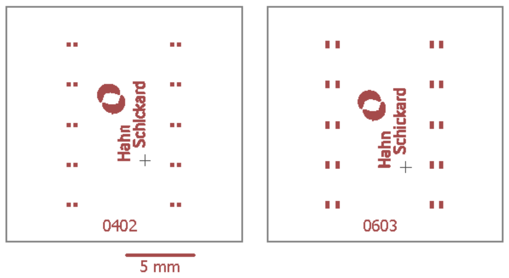
2.1. Shear Strength Characterization
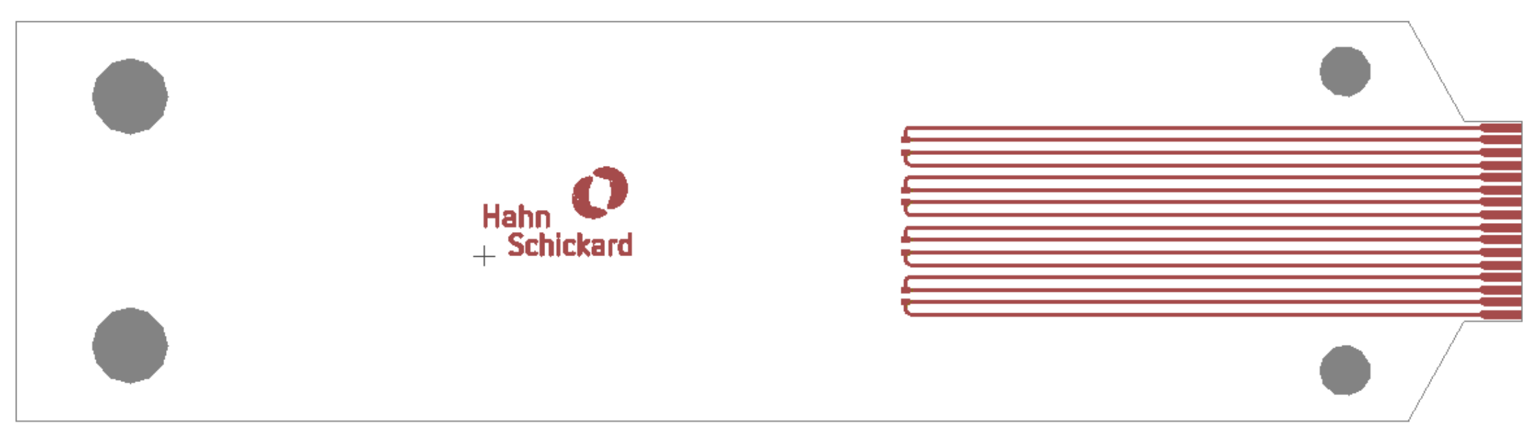
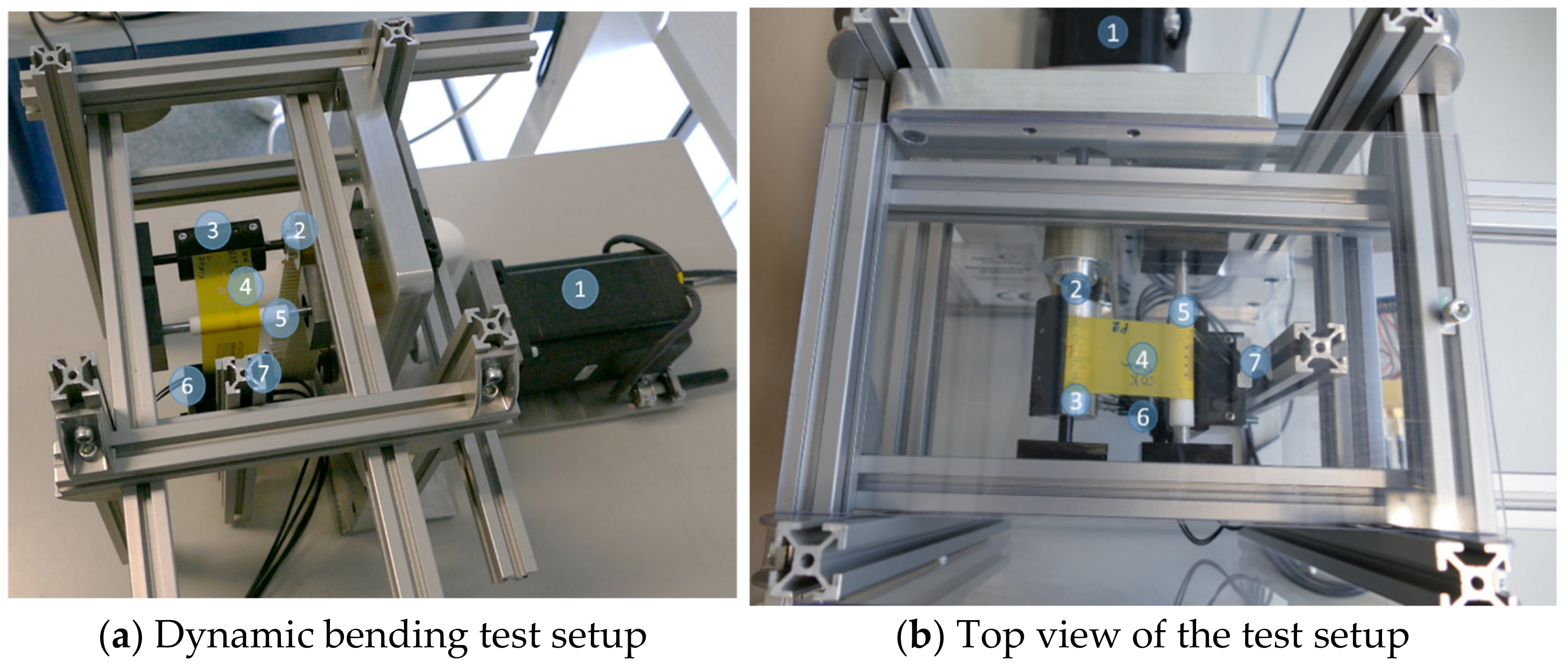
2.2. Dynamic Bending Characterization
3. Results
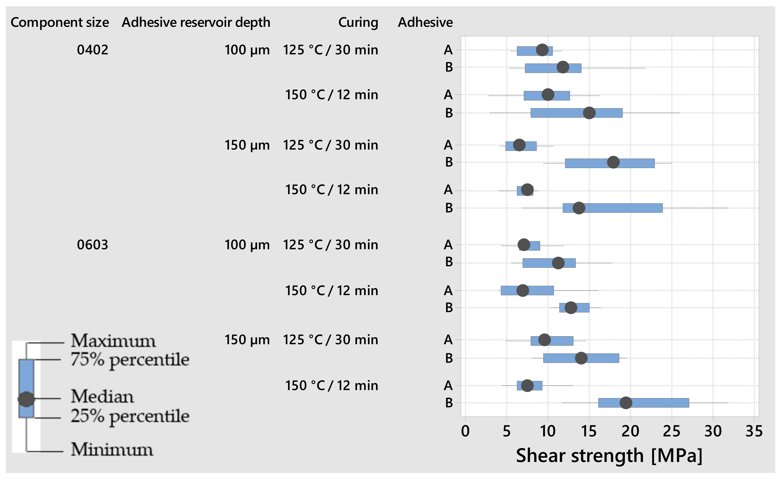
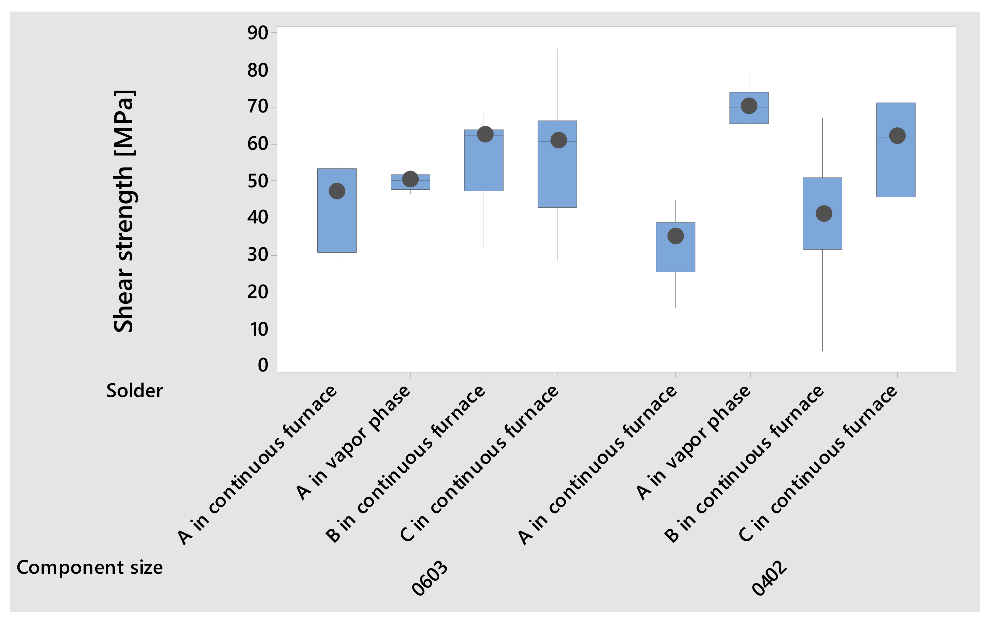
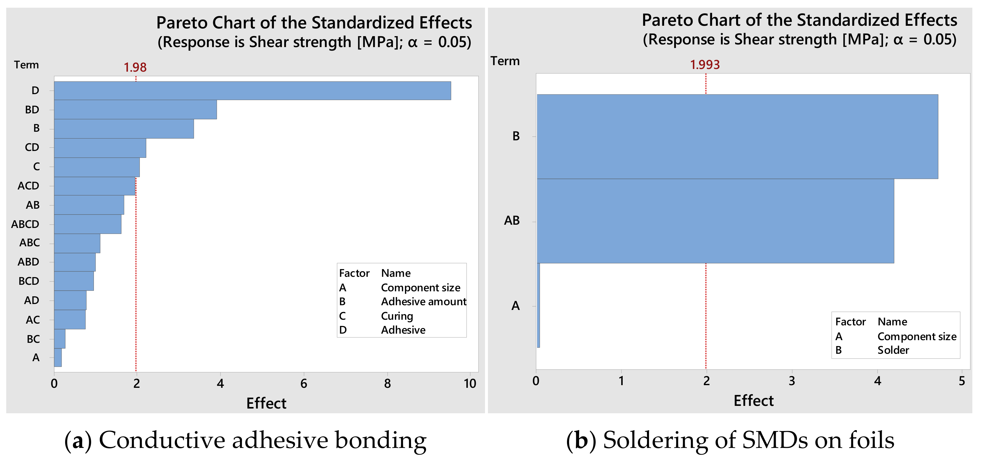
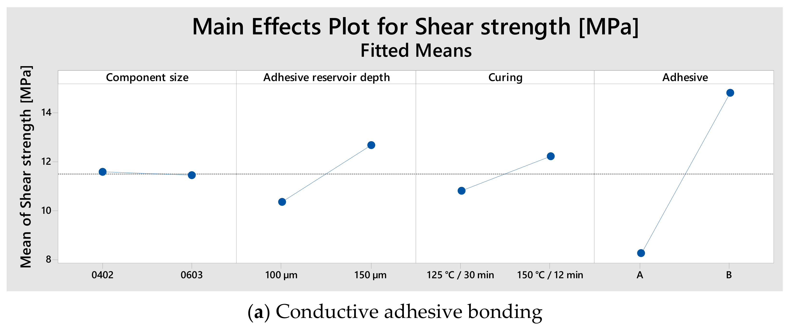
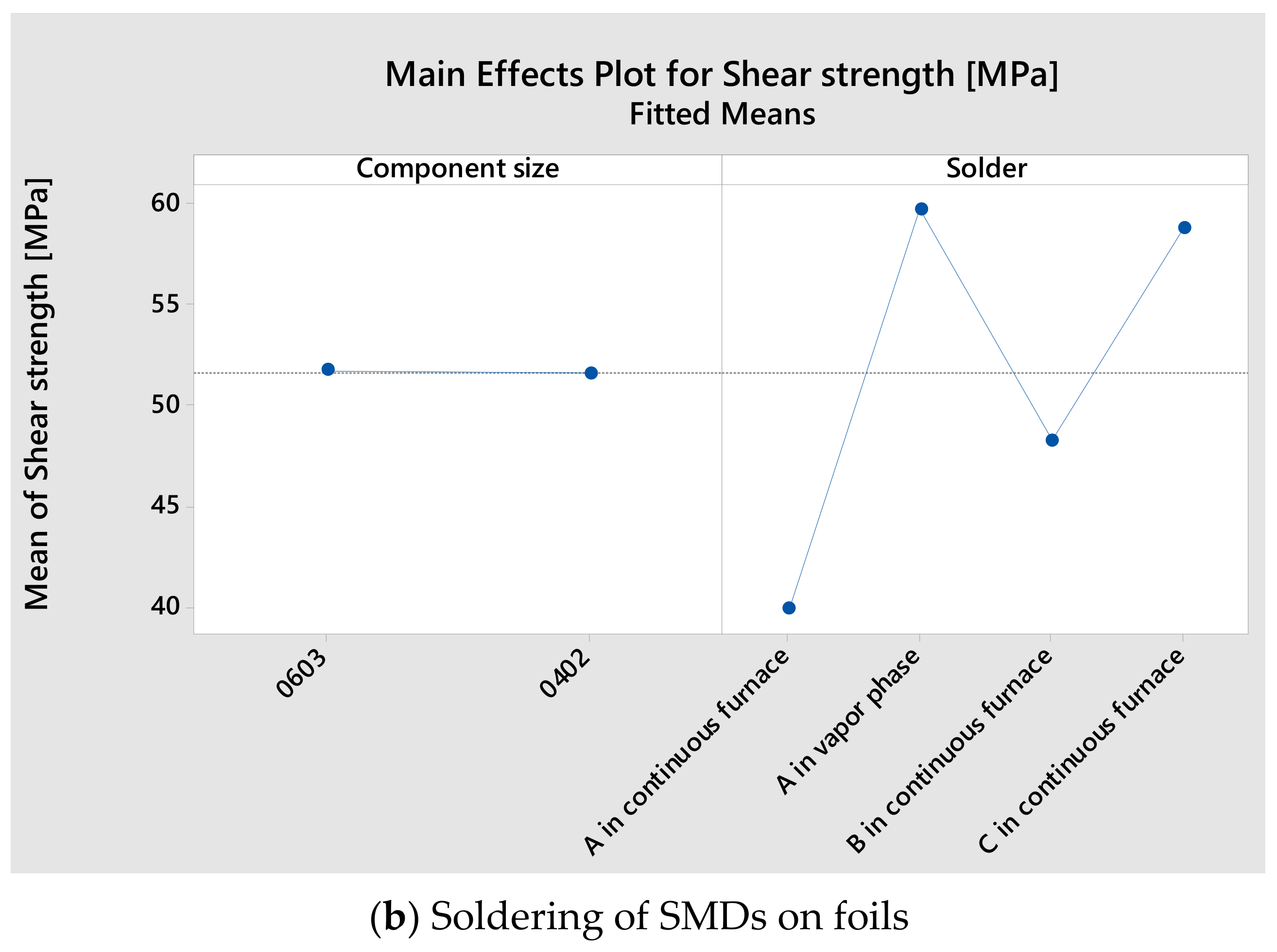
3.1. Shear Strength
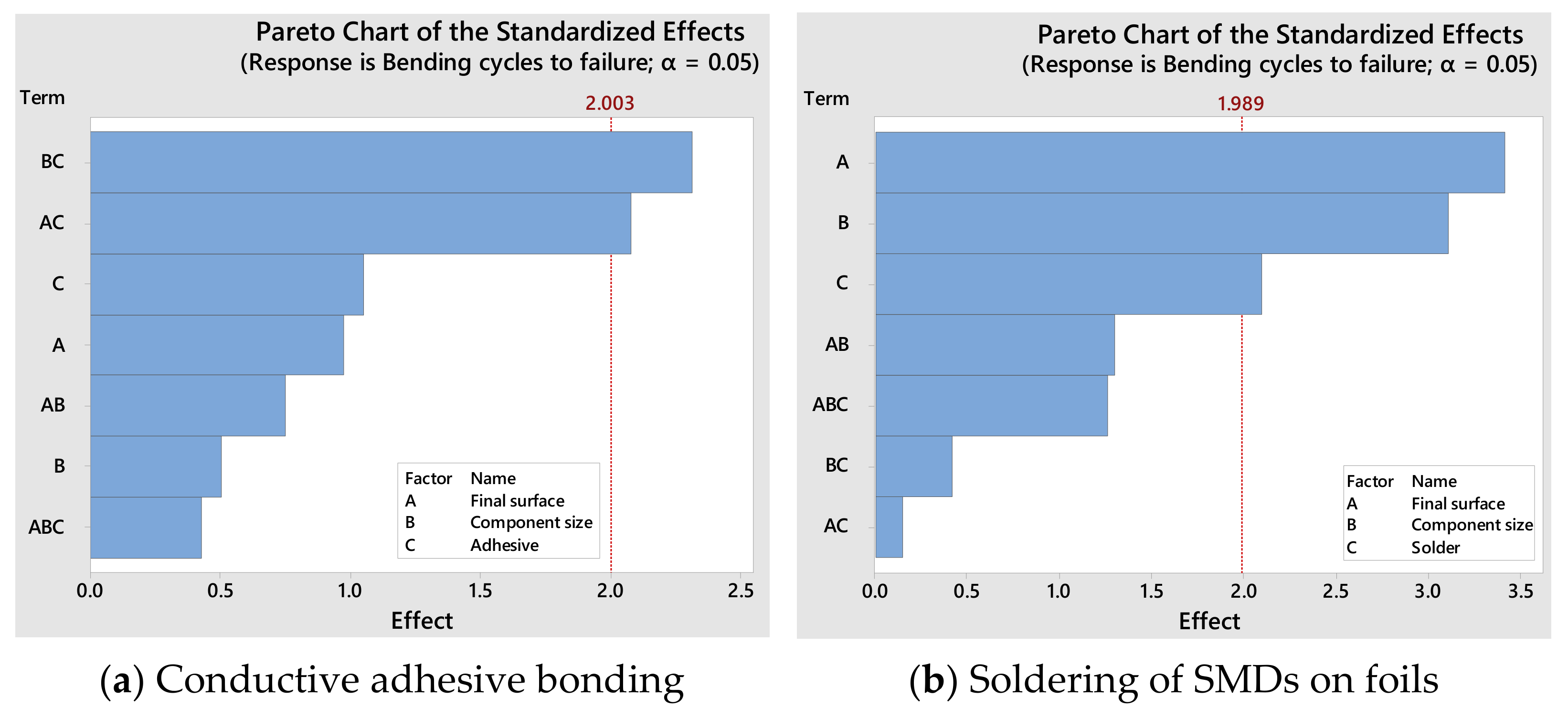
3.2. Bending Characterization
4. Discussion
5. Conclusions
- Based on shear strength tests, it can be concluded that the choice of the conductive adhesive is the most important factor for ensuring that the mechanical connection is maintained. The variation of process parameters tends to play a minor role.
- Soldering enables higher shear strength values than conductive adhesive bonding.
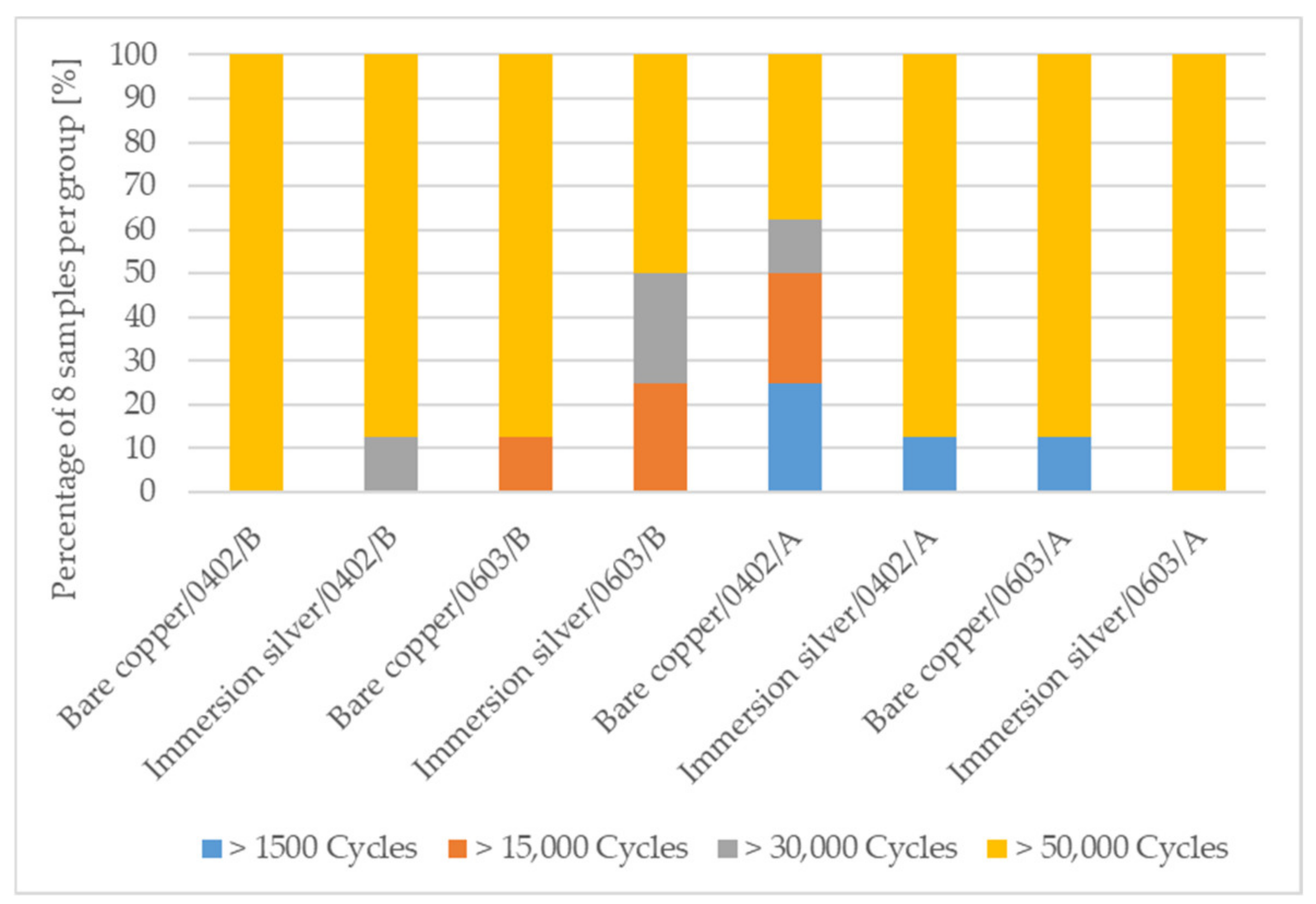
- In the dynamic bending test, more samples endured to the end of the test of 50,000 cycles in the conductive adhesive bonding group than in the soldering group.
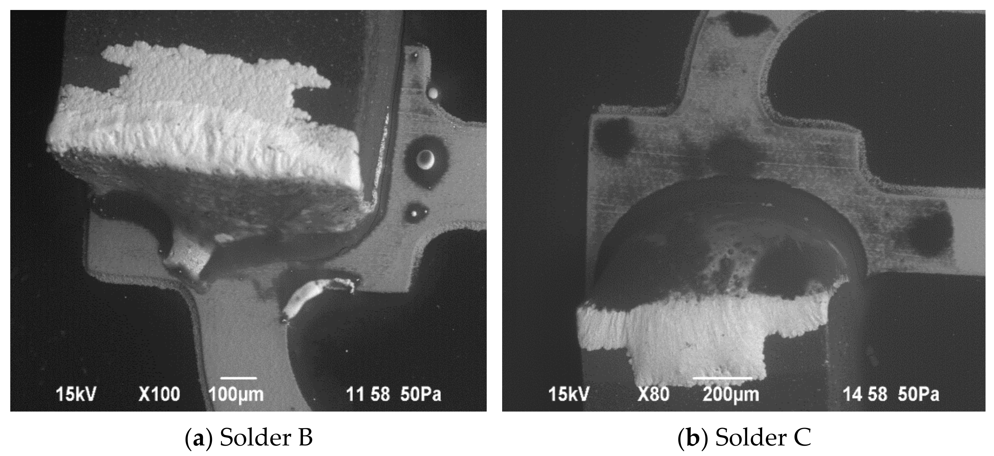
- In the soldering group, solder C on bare copper surface achieved more cycles to failure than the other solders.
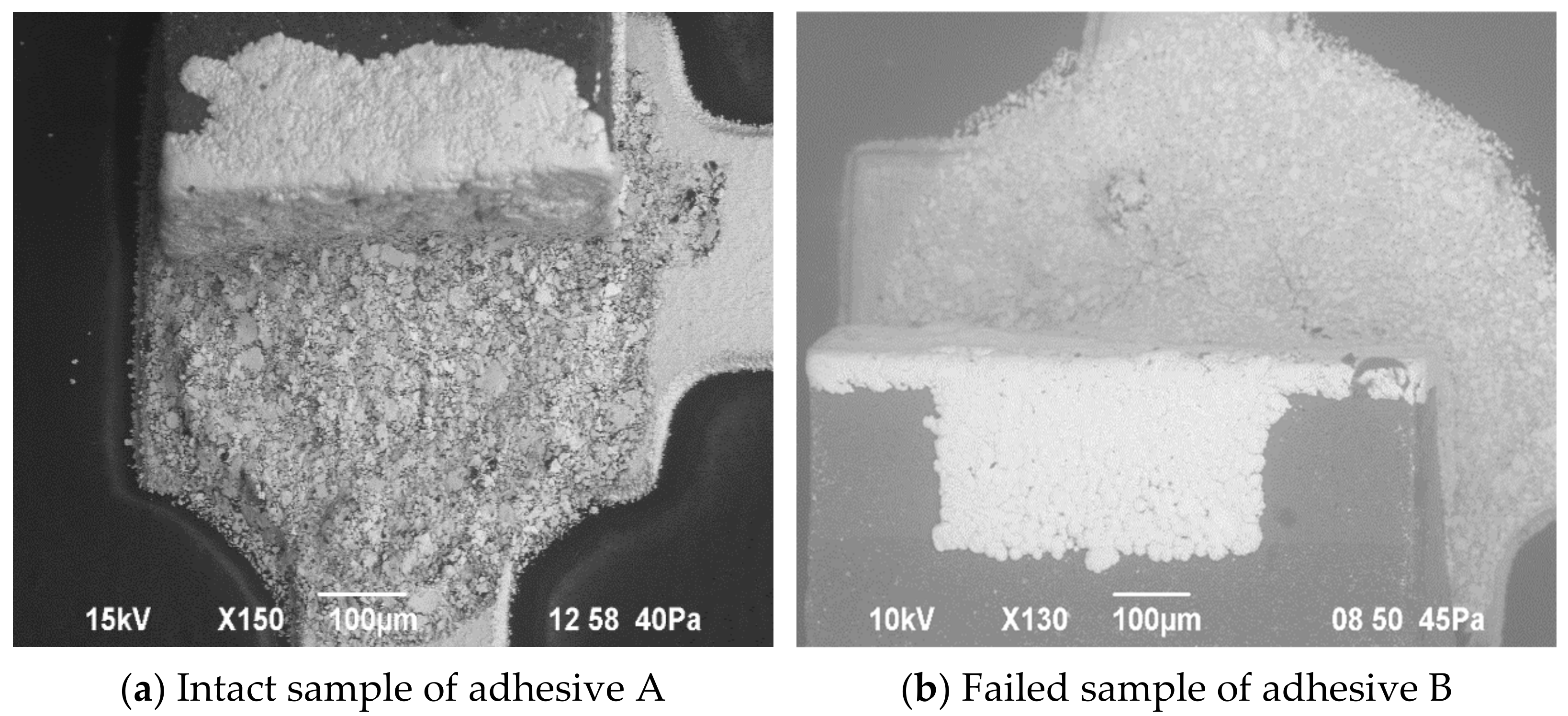
- In the conductive adhesive bonding group, adhesive H20E on immersion silver surface finish achieved more cycles to failure than the other adhesive.
- The bare copper surface is more suitable than the immersion silver surface finish for reliable solderability.
- The immersion silver surface finish is better than the bare copper surface for reliable conductive adhesive bonding.
Author Contributions
Funding
Institutional Review Board Statement
Informed Consent Statement
Data Availability Statement
Acknowledgments
Conflicts of Interest
References
- Corzo, D.; Tostado-Blázquez, G.; Baran, D. Flexible Electronics: Status, Challenges and Opportunities. Front. Electron. 2020, 1, 594003. [Google Scholar] [CrossRef]
- Rogers, J.A.; Someya, T.; Huang, Y. Materials and Mechanics for Stretchable Electronics. Science 2010, 327, 1603–1607. [Google Scholar] [CrossRef] [PubMed] [Green Version]
- Su, Y.; Liu, Z.; Kim, S.; Wu, J.; Huang, Y.; Rogers, J.A. Mechanics of stretchable electronics with high fill factors. Int. J. Solids Struct. 2012, 49, 3416–3421. [Google Scholar] [CrossRef] [Green Version]
- Landesberger, C.; Palavesam, N.; Hell, W.; Drost, A.; Faul, R.; Gieser, H.; Bonfert, D.; Bock, K.; Kutter, C. Novel processing scheme for embedding and interconnection of ultra-thin IC devices in flexible chip foil packages and recurrent bending relia-bility analysis. In Proceedings of the 2016 International Conference on Electronics Packaging (ICEP), Hokkaido, Japan, 20–22 April 2016; pp. 473–478. [Google Scholar] [CrossRef]
- Nathan, A.; Ahnood, A.; Cole, M.T.; Lee, S.; Suzuki, Y.; Hiralal, P.; Bonaccorso, F.; Hasan, T.; Garcia-Gancedo, L.; Dyadyusha, A.; et al. Flexible Electronics: The Next Ubiquitous Platform. Proc. IEEE 2012, 100, 1486–1517. [Google Scholar] [CrossRef]
- Brand, J.V.D.; Kusters, R.; Barink, M.; Dietzel, A. Flexible embedded circuitry: A novel process for high density, cost effective electronics. Microelectron. Eng. 2010, 87, 1861–1867. [Google Scholar] [CrossRef]
- Lu, D.; Wong, C.P. Materials for Advanced Packaging; Springer: New York, NY, USA, 2017; pp. 373–419. [Google Scholar]
- Saleh, R.; Mohn, F.; Barth, M.; Eberhardt, W.; Zimmermann, A. Digital Process Chain for Processing of Bend-Sensitive Functional Structures on a Flexible Substrate. IEEE Trans. Compon. Packag. Manuf. Technol. 2021, 11, 1417–1425. [Google Scholar] [CrossRef]
- Saleh, R.; Barth, M.; Eberhardt, W.; Zimmermann, A. Bending Setups for Reliability Investigation of Flexible Electronics. Micromachines 2021, 12, 78. [Google Scholar] [CrossRef] [PubMed]
- Khan, Y.; Thielens, A.; Muin, S.; Ting, J.; Baumbauer, C.; Arias, A.C. A New Frontier of Printed Electronics: Flexible Hybrid Electronics. Adv. Mater. 2019, 32, e1905279. [Google Scholar] [CrossRef] [PubMed]
- Harris, K.D.; Elias, A.; Chung, H.-J. Flexible electronics under strain: A review of mechanical characterization and durability enhancement strategies. J. Mater. Sci. 2016, 51, 2771–2805. [Google Scholar] [CrossRef]
- Khan, S.; Lorenzelli, L.; Dahiya, R.S. Technologies for Printing Sensors and Electronics Over Large Flexible Substrates: A Review. IEEE Sens. J. 2015, 15, 3164–3185. [Google Scholar] [CrossRef]
- Jager, J.; Buschkamp, S.; Werum, K.; Glaser, K.; Grozinger, T.; Eberhardt, W.; Zimmermann, A. Contacting Inkjet-Printed Silver Structures and SMD by ICA and Solder. IEEE Trans. Compon. Packag. Manuf. Technol. 2022, 12, 1232–1240. [Google Scholar] [CrossRef]
- Logothetidis, S.; Sleiman, A.; Sayers, P.W.; Zeze, D.A.; Mabrook, M.F. Handbook of Flexible Organic Electronics; Elsevier: Amsterdam, The Netherlands, 2015; pp. 143–169. [Google Scholar]
- Hirman, M.; Steiner, F. Shear Strength of Conductive Adhesive Joints on Rigid and Flexible Substrates Depending on Adhesive Quantity. J. Electr. Eng. 2016, 67, 177–184. [Google Scholar] [CrossRef] [Green Version]
- Ende, D.A.V.D.; Hendriks, R.; Cauchois, R.; Kusters, R.H.L.; Cauwe, M.; Groen, W.A.; Brand, J.V.D. Photonic Flash Soldering of Thin Chips and SMD Components on Foils for Flexible Electronics. IEEE Trans. Compon. Packag. Manuf. Technol. 2014, 4, 1879–1886. [Google Scholar] [CrossRef]
- Hirman, M.; Neuhofer, T.; Steiner, F. Bend Testing of SMD Chip Resistors Glued on Flexible Substrates. In Proceedings of the 2019 42nd International Spring Seminar on Electronics Technology (ISSE), Wroclaw, Poland, 15–19 May 2019; p. 18938459. [Google Scholar] [CrossRef]
- Hirman, M.; Navratil, J.; Steiner, F.; Dzugan, T.; Hamacek, A. SMD Components Assembly on a Flexible Substrate by Non-Conductive Adhesives. In Proceedings of the 2018 41st International Spring Seminar on Electronics Technology (ISSE), Zlatibor, Serbia, 16–20 May 2018; p. 18058604. [Google Scholar] [CrossRef]
- Koscielski, M.; Sitek, J. Influence of curing conditions on mechanical properties and reliability of the interconnects made by ICA for printed electronics with micro additives. In Proceedings of the 5th Electronics System-Integration Technology Conference (ESTC), Helsinki, Finland, 16–18 September 2014; p. 14762798. [Google Scholar] [CrossRef]
- Balogh, B.; Illyefalvi-Vitez, Z.; Kotora, G.; Harvey, T.; Kirkpatrick, D.; Farmer, G. Qualification and Reliability Tests of Flexible Printed Circuits. In Proceedings of the 2007 30th International Spring Seminar on Electronics Technology (ISSE), Cluj-Napoca, Romania, 9–13 May 2007; pp. 82–87. [Google Scholar] [CrossRef]
- EPO-TEK®® H20E Datasheet. 2021. Available online: https://www.epotek.com/docs/en/Datasheet/H20E.pdf (accessed on 5 June 2022).
- LOCTITE ABLESTIK 3880 Datasheet. 2015. Available online: http://tds.henkel.com/tds5/Studio/ShowPDF/243NEW-EN?pid=ABLESTIK3880&format=MTR&subformat=REAC&language=EN&plant=WERCS (accessed on 7 June 2022).
- Zhang, S.; Qi, X.; Yang, M.; Cao, Y.; Lin, T.; He, P.; Paik, K.-W. A study on the resistivity and mechanical properties of modified nano-Ag coated Cu particles in electrically conductive adhesives. J. Mater. Sci. Mater. Electron. 2019, 30, 9171–9183. [Google Scholar] [CrossRef]
- Kim, H.-J.; Paik, K.-W. Adhesion and Reliability of Anisotropic Conductive Films (ACFs) Joints on Organic Solderability Preservatives (OSPs) Metal Surface Finish. J. Electron. Mater. 2008, 37, 1003–1011. [Google Scholar] [CrossRef]
- Lee, J.; Cho, C.S.; Morris, J.E. Electrical and reliability properties of isotropic conductive adhesives on immersion silver printed-circuit boards. Microsyst. Technol. 2008, 15, 145–149. [Google Scholar] [CrossRef]
- Arra, M.; Shangguan, D.; Xie, D.; Sundelin, J.; Lepistö, T.; Ristolainen, E. Study of immersion silver and tin printed-circuit-board surface finishes in lead-free solder applications. J. Electron. Mater. 2004, 33, 977–990. [Google Scholar] [CrossRef]
- Wang, W.; Choubey, A.; Azarian, M.H.; Pecht, M. An Assessment of Immersion Silver Surface Finish for Lead-Free Electronics. J. Electron. Mater. 2009, 38, 815–827. [Google Scholar] [CrossRef]
- Kang, H.; Rajendran, S.H.; Jung, J.P. Low Melting Temperature Sn-Bi Solder: Effect of Alloying and Nanoparticle Addition on the Microstructural, Thermal, Interfacial Bonding, and Mechanical Characteristics. Metals 2021, 11, 364. [Google Scholar] [CrossRef]
- Wang, Q.; Zhang, S.; Lin, T.; Zhang, P.; He, P.; Paik, K.-W. Highly mechanical and high-temperature properties of Cu–Cu joints using citrate-coated nanosized Ag paste in air. Prog. Nat. Sci. 2021, 31, 129–140. [Google Scholar] [CrossRef]
- Rahn, A. Bleifrei Löten Ein Leitfaden für Die Praxis; Eugen G. Leuze Verlag: Bad Saulgau, Germany, 2004. [Google Scholar]


| Factors | Level 1 | Level 2 | Level 3 |
|---|---|---|---|
| Component size | 0603 | 0402 | - |
| Solder type | SAC (solder A) | SnBi (solder B) | SnBiAg (solder C) |
| Soldering process | Continuous furnace | Vapor phase (just for solder A) | - |
| Conductive adhesive | Adhesive A | Adhesive B | - |
| Adhesive reservoir depth | 150 µm | 100 µm | - |
| Curing profile | 150 °C/12 min | 125 °C/30 min | - |
| Factors | Level 1 | Level 2 | Level 3 |
|---|---|---|---|
| Component size | 0603 | 0402 | - |
| Final metal surface on substrate | Bare copper | Immersion silver | |
| Solder type | SAC (solder A) | SnBi (solder B) | SnBiAg (solder C) |
| Conductive adhesive | Adhesive A | Adhesive B | - |
Publisher’s Note: MDPI stays neutral with regard to jurisdictional claims in published maps and institutional affiliations. |
© 2022 by the authors. Licensee MDPI, Basel, Switzerland. This article is an open access article distributed under the terms and conditions of the Creative Commons Attribution (CC BY) license (https://creativecommons.org/licenses/by/4.0/).
Share and Cite
Saleh, R.; Schütt, S.; Barth, M.; Lang, T.; Eberhardt, W.; Zimmermann, A. Assembly of Surface-Mounted Devices on Flexible Substrates by Isotropic Conductive Adhesive and Solder and Lifetime Characterization. Micromachines 2022, 13, 1240. https://doi.org/10.3390/mi13081240
Saleh R, Schütt S, Barth M, Lang T, Eberhardt W, Zimmermann A. Assembly of Surface-Mounted Devices on Flexible Substrates by Isotropic Conductive Adhesive and Solder and Lifetime Characterization. Micromachines. 2022; 13(8):1240. https://doi.org/10.3390/mi13081240
Chicago/Turabian StyleSaleh, Rafat, Sophie Schütt, Maximilian Barth, Thassilo Lang, Wolfgang Eberhardt, and André Zimmermann. 2022. "Assembly of Surface-Mounted Devices on Flexible Substrates by Isotropic Conductive Adhesive and Solder and Lifetime Characterization" Micromachines 13, no. 8: 1240. https://doi.org/10.3390/mi13081240
APA StyleSaleh, R., Schütt, S., Barth, M., Lang, T., Eberhardt, W., & Zimmermann, A. (2022). Assembly of Surface-Mounted Devices on Flexible Substrates by Isotropic Conductive Adhesive and Solder and Lifetime Characterization. Micromachines, 13(8), 1240. https://doi.org/10.3390/mi13081240