1. Introduction
Laser micromachining of grooves with ultrashort laser pulses is a versatile process that can be applied for various applications, such as cutting through thin metal foils [
1], dicing silicon wafers [
2], engraving implants made of titanium alloy to enhance osseointegration [
3] or engraving cutting tools to reduce the force and friction in mechanical machining of aluminum [
4]. In micromachining processes with pulsed lasers, a relative movement between the laser beam and the workpiece is created either by deflecting the laser beam over the processed surface by means of a scanner or by moving the workpiece past the static beam by means of a linear axis. In both cases, multiple scans over the same contour are typically performed to fabricate grooves with a required depth. The dimensions of the micromachined grooves, i.e., the depth and width or their aspect ratio (depth/width), have a major influence on the performance of the respective application: A complete cut through the sample is required in the cutting of thin metal sheets [
1]. In open microfluidic systems, a higher flow velocity of liquids is achieved for grooves with a higher aspect ratio [
5,
6]. Grooves with higher aspect ratios also enhanced the performance of engraved cutting tools in mechanical machining [
4].
The laser micromachined grooves with depths of a few tens up to several hundreds of micrometers typically feature a V-shaped geometry in metals [
7,
8], semiconductors [
2,
9], dielectrics [
10] and polymers [
11]. The resulting width of the grooves mainly depends on the diameter of the laser beam, the incident peak fluence and the material-specific ablation threshold [
12]. Experimental results revealed the influence of various processing parameters on the resulting depth of a micromachined groove, such as the pulse energy or the irradiated peak fluence, the scanning speed, the number of scans over the surface [
2,
8,
9] and the ablation threshold [
12]. The groove’s depth can be increased by multiple scans, whereas high pulse energies [
2,
8] and low scanning speeds [
9] result in a higher increase in the depth for each scan. The progress of the depth of micromachined grooves exhibited a linear correlation with the number of scans for cutting through thin metal foils with a thickness of up to 50 µm [
1] and for micromachining of shallow grooves with a depth of up to a few tens of micrometers in semiconductors [
9]. A constant deepening rate of laser-processed grooves was achieved up to an aspect ratio (depth/width) of approximately 1.5 [
6], which corresponds to the phase of constant depth progress observed in areal micromachining of metals [
13] and silicon [
14], where the aspect ratio is typically < 1. The depth progress gradually slows down with increasing depth of the groove [
6,
8,
9], reaching a limit when the absorbed fluence is reduced to the value of the ablation threshold everywhere on the walls of the groove [
2]. This behavior corresponds to the one found for percussion drilling of microholes, where a decreasing rate of the depth progress was observed with the increasing number of applied pulses, which finally stagnated at the maximum reachable depth [
15,
16]. It is not energy-efficient to process until this maximum depth is reached since the rate of the depth progress decreases despite the constant applied average power.
The in situ measurement of the current depth during processing has already been demonstrated using optical coherence tomography for percussion drilling of microholes [
15,
17] and for areal micromachining [
18,
19]. This approach is also suitable for the production of grooves, as shown in [
6] for groove depths up to 500 µm. The prediction of the reachable depth of the grooves or the estimate of the rate of the depth progress during laser micromachining, which would allow for the design of an efficient and productive machining process, has proven to be difficult due to the influence and interplay of various laser parameters, scanning parameters and material properties, including the groove’s depth itself. A numerical model for the calculation of the groove geometry is proposed in [
20], but the model does not consider the increased absorptance in V-shaped grooves that is caused by multiple reflections, which were observed in raytracing simulations [
21].
A simplified analytical model for the prediction of the depth progress in laser machining of V-shaped grooves with ultrashort laser pulses is therefore introduced in the following section. The model was experimentally verified for the case of laser micromachining of grooves with a depth of up to µm in the Ti-alloy Ti6Al4V with different pulse energies, repetition rates, scanning speeds and number of scans.
2. Analytical Model for the Prediction of the Depth and Width of Laser Micromachined Grooves
An analytical, recursive model for the calculation of the depth progress of laser-processed V-shaped grooves in metals can be derived in analogy to the model for percussion drilling of conical microholes as presented in [
15].
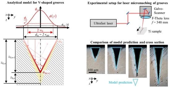
Figure 1 illustrates the assumptions made for the model as seen by the cross section in the
y–
z-plane perpendicular to the scanning direction
x.
The pulses of a Gaussian laser beam are irradiated onto the metal sample (the grey hatched cross section) at normal incidence (i.e., in the
z-direction). At the surface of the workpiece, the transversal distribution of the incident fluence (red curve) is given by
where
x − xC and
y − yC are the distances from the centre of the laser beam located at (
xC,
yC),
w0 is the beam radius and
ϕ0 denotes the peak fluence, which is given by
where
EP is the pulse energy. At normal incidence, material removal by ablation on the surface occurs when the locally absorbed fluence
, where
A is the material-specific absorptivity at the wavelength of the incident radiation, exceeds the value
of the ablation threshold, where
lE denotes the effective penetration depth of the absorbed energy density and
hV denotes the volume-specific enthalpy required for heating and complete vaporization of the material. The effective penetration depth
lE is dominated either by the optical penetration depth or by the electron heat diffusion length, depending on the peak fluence of the incident radiation [
22]. Additionally,
lE and thus
ϕth decrease with increasing number of pulses applied to the surface [
23] due to the so-called incubation effect [
24]. The incubation effect saturates after about 100 pulses, whereupon the effective penetration depth and the ablation threshold are not significantly decreased further by additional pulses [
23]. For the sake of simplicity, the energy penetration depth
lE and thus the ablation threshold
ϕth are assumed to be constant over the entire process for the presented analytical model. The error caused by this simplification during the first 100 pulses is negligible as typically, more than several thousands of pulses are applied to each location for the production of laser machined grooves.
The width of the groove
dG resulting from material removal corresponds to two times the ablation radius
rabl and is calculated by [
15]
since no ablation can occur at the locations
where the fluence absorbed on the surface of the workpiece is lower than the ablation threshold. It is implicitly premised here that the spatial overlap of consecutive pulses along the scan path in the
x-direction is sufficiently large to ensure a constant width of the groove. The spatial pulse overlap Ω
x is defined by
where
denotes the spatial offset between the impact locations of two consecutive pulses,
vx is the scanning speed and
frep is the pulse repetition rate. A constant groove width
dG is typically achieved with a spatial pulse overlap ranging from 30% to 95% [
2].
The proposed recursive model is based on the assumption that the groove depth
zG,n after
n ∈ 1,2,…
N scans can be calculated by
where
zG,n − 1 denotes the groove depth after
n − 1 scans and
zS,n denotes the depth ablated by the
nth scan (cf.
Figure 1). The overall absorptance
ηA resulting from multiple reflections inside the V-shaped groove may be calculated assuming specular reflections of a ray, which is incident in
z-direction and is found to be [
25]
where
NR denotes the number of reflections of the ray until it leaves the groove again. This number of reflections depends on the aspect ratio of the V-shaped groove and is given by [
25]
where
is the rounding up function.
The energy
dEA,n(
xj) absorbed from one single pulse of a Gaussian laser beam during the
nth scan along the groove at the location
x in a stripe with the width
dx inside the groove between the edges at
y = ±
dG/2 amounts to
where
is the location of the beam axis along the
x-axis at the time at which the
jth pulse hits the workpiece and where
j ∈ ℤ and
yC was set to zero for the beam, which is centred on the groove.
The overall absorptance
ηA(
dG,
zG,n − 1) only defines the amount of energy
dEA,n,j(
x) absorbed in the groove but does not specify the transversal distribution of the fluence in the
y–
z-plane (cf.
Figure 1). As shown by raytracing simulations of V-shaped capillaries in [
21], the effect of multiple reflections causes an elevated absorbed fluence near the tip of the groove. As a simple approximation for the transversal distribution of the absorbed fluence in the groove, it is assumed in the following that the absorbed fluence linearly increases with the depth along the sidewalls of the V-shaped groove in the
y–
z-plane. In analogy to the model presented for percussion drilling [
15] and assuming that multiple reflections only occur normal to the axis of the groove, the distribution of the absorbed fluence at a given location
x along the groove is assumed to start with
ϕth at the edge of the groove (at
y = ±
dG/2) and end with
ϕtip,n,j(
x) at the tip of the groove (
y =
yC = 0). With this assumption, the energy
dEA,n,j(
x) absorbed at the location
x from a single pulse
j in a stripe of width
dx amounts to
where
is the length of the two sidewalls together measured in the
y–
z-plane (cf.
Figure 1). As both Equations (10) and (11) describe the same energy, it follows that
Inserting Equation (2) and replacing the integral with
, where erf is the well-known error function, one finds that the fluence deposited at the tip of the groove with the depth
zG,n − 1 at the location
x by the
jth pulse during the
nth scan is given by
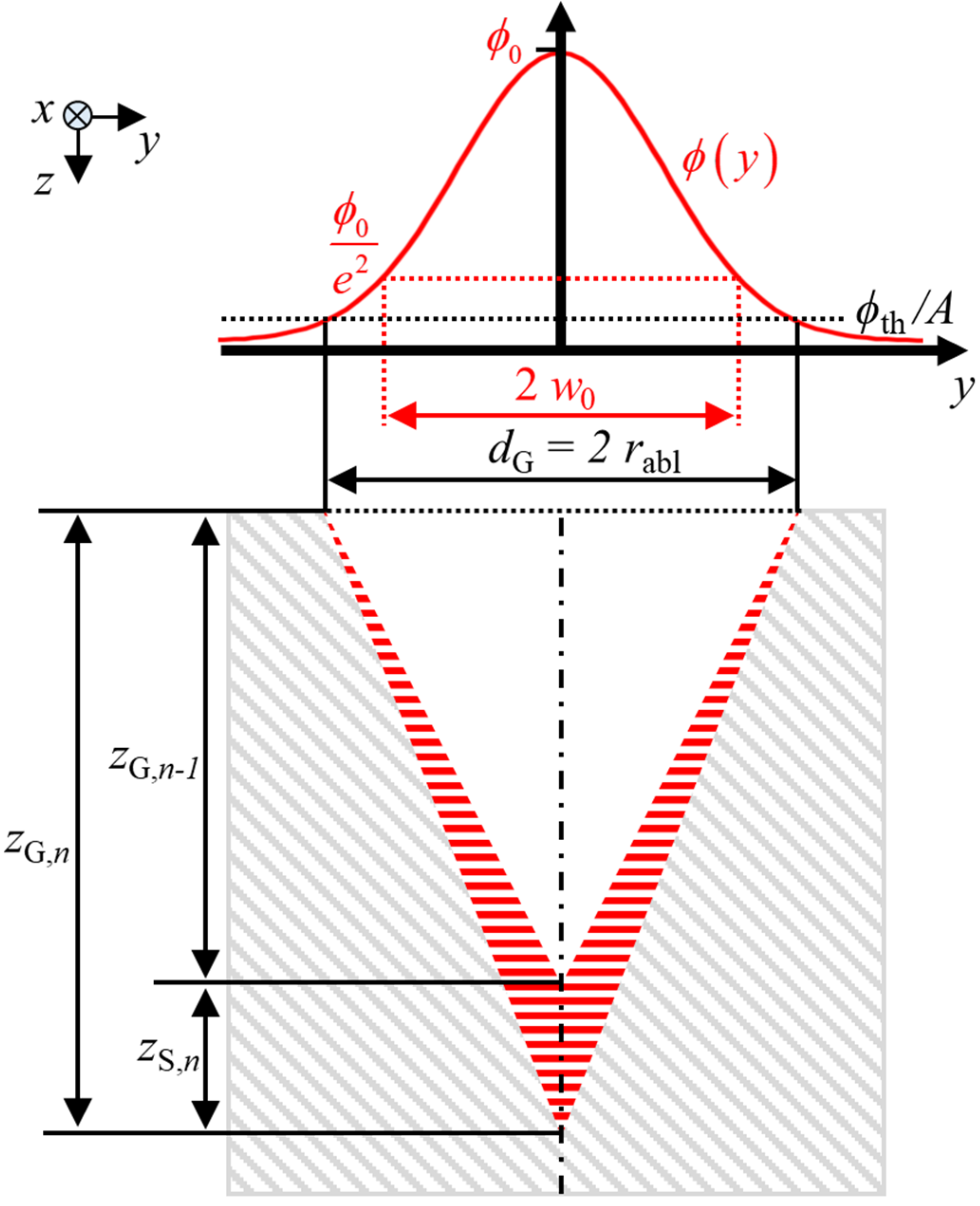
Figure 2 shows a sequence of distributions of the fluence
ϕtip,n,j(
x) with a spatial offset of
δx each absorbed at the tip of the groove around an arbitrary point
x0. For the sake of clarity, the figure is divided into two parts showing the pulses with
j ≤ 0 in
Figure 2a) and the pulses with
j ≥ 0 in
Figure 2b). The pulses are numbered in such a way that the beam axis coincides with
x0 at the moment when the 0th pulse hits the workpiece (
xC,0 =
x0). Considering this diagram, it becomes evident that from the perspective of a point (
x =
x0,
y = 0) located at
x0 somewhere along the centre line of the groove, the individual pulses of a scan can only contribute to the ablation of the groove at this point
x0 as long as the fluence absorbed at the tip
ϕtip,n,j(
x0) >
ϕth exceeds the ablation threshold
ϕth. The fluence that is absorbed at the tip of the groove from each of the pulses
j of one scan (with
j = …, −3, −2, −1, 0, 1, 2, 3, …) at the location
x =
x0 is given by the intersection of the fluence distribution
ϕtip,n,j(
x) with the ordinate at
x =
x0, as indicated by the colored small arrows in
Figure 2.
In the example depicted in
Figure 2, only the pulses from
j = −2 to
j = 2 contribute to material ablation at (
x =
x0,
y = 0), as only their fluences
ϕtip,n,j(
x0) exceed the ablation threshold
ϕth, whose value is indicated by the black dotted line. The intersection
of the fluence distribution
ϕtip,n,j(
x) with the ablation threshold
ϕth determines the maximum number of pulses
jabl,n contributing to ablation in this direction. Using Equation (12) and solving for
jabl,n yields
As a result, the depth ablated by the
nth scan
zS,n as seen by the spot
x =
x0 located on the centre line of the groove corresponds to the accumulated depth ablated by the pulses
to
and can be calculated by
where
means rounding off and
zP,n,j(
x) denotes the depth ablated by the pulse
j during the
nth scan. According to the logarithmic ablation law [
23,
26], the depth increment ablated by a single pulse is given by
In the present model, a constant absorptance ηA (dG, zG,n − 1) as given by Equations (8) and (9) is assumed during one scan over the groove. This induces a negligible error since ηA changes very slowly with an increasing number n of scans as long as zS,n << dG, which is typically the case in micromachining processes with a reasonable pulse overlap Ωx in the range of 30–95%.
With the above equations, the progress of the increasing groove depth zG,n can be recursively calculated as a function of the number n of scans. A useful way to proceed is by starting with the calculation of the constant parameters that are not affected by the recursive calculation, such as the spatial offset δx between the impact locations of two consecutive pulses using Equation (6). Furthermore, the peak fluence ϕ0 and ablation threshold ϕth can be calculated with Equations (2) and (3), respectively, in order to determine the width of the groove dG using Equation (4). With the first scan (n = 1) at the beginning of the recursive calculation, a very small value should be chosen for the initial groove depth, e.g., zG,0 = 1 nm (zG,0 ≠ 0), so as not to divide by 0 in the subsequent calculation of the absorptance ηA (dG, zG,0) in Equations (8) and (9). Then, the maximum number of pulses jabl,1 contributing to ablation in each direction is calculated using Equation (13), followed by the calculation of the fluence ϕtip,1,j(x) deposited at the tip of the groove with Equation (12) for each contributing pulse j during this first scan. The depth increment zP,1,j(x) ablated by each pulse j is calculated using Equation (15) and accumulated according to Equation (14). Then, the accumulated depth of the first scan zS,1 is added to the initial groove depth zG,0 as given by Equation (7). The calculation of the absorptance ηA (dG, zG,1) of the groove with increased depth zG,1 starts the second loop of the recursive calculation. This procedure must be repeated n times to receive the groove depth zG,n after micromachining with n scans.
The absorbed fluence
ϕtip,n,j(
x) at the tip of the groove decreases with increasing groove depth due to the increasing length of the sidewalls
. This reduction is partially compensated by an increased absorptance
ηA (
dG,
zG,n−1) due to the increasing number
NR of reflections within the groove (cf. Equations (8) and (9)). The maximum attainable groove depth
zG,∞ obtained after
n → ∞ scans is reached when the fluence
ϕtip,n,j(
x =
xC) at the tip of the V-shaped groove converges to the value of the ablation threshold
ϕth. The maximum groove depth
zG,∞ can therefore be found with Equation (12) by setting
ϕtip,n,j(
x =
xC) =
ϕth, and solving for
zG,∞, which yields
where
η∞ =
ηA (
dG,
zG,∞−1) denotes the absorptance of a groove micromachined with ∞−1 scans. As the absorptance, in turn, depends on the groove depth
zG,n−1 (cf. Equations (8) and (9)), the maximum groove depth
zG,∞ cannot be calculated directly but has to be found by a recursive calculation using Equation (7). Assuming a high aspect ratio
zG,∞/
dG of the final groove, the absorptance can, however, be approximated to be
η∞ ≈ 1, and the maximum achievable groove depth
zG,∞ obtained with a given parameter set can directly be estimated using Equation (16) by setting
η∞ = 1. Equation (16) also shows that the maximum achievable groove depth does neither depend on the repetition rate
frep nor on the scanning parameters such as the scanning speed
vx and that—for a given beam radius
w0 and with the material-specific value of
ϕth—it can only by increased by increasing the pulse energy
EP.
It is noted that the model for the calculation of the depth progress presented in this section only requires five generally known laser and scanning parameters, namely the pulse energy EP, the repetition rate frep, the radius w0 of the laser beam, the scanning speed vx, and the number of scans n, as well as the three material parameters, absorptivity A, energy penetration depth lE, and the enthalpy hV for heating and complete vaporization of the material.
3. Experimental Verification of the Analytical Model
The model for the prediction of the depth and width of laser micromachined grooves derived in the previous section was compared to experimental results obtained by micromachining samples with a size of 50 × 50 mm² and a thickness of 1 mm made of Ti6Al4V (ASTM Grade 5), a Ti-alloy often used in the aerospace industry and for biomechanical applications due to the high specific strength, corrosion resistance and biocompatibility. The ultrafast laser system
Pharos from
Light Conversion with a wavelength of 1030 nm was used for micromachining. The laser emitted pulses with a pulse duration of 260 fs. The circularly polarized laser beam with a Gaussian intensity distribution had a beam propagation factor of M² < 1.3. The beam was scanned over the surface of the samples by means of a Galvanometer-Scanner (
Scanlab,
intelliSCAN 30) and was focused by an F-Theta lens (
Sill Optics,
S4LFT1330/328) with a focal length of 340 mm, resulting in a focal radius of
w0 = 55 ± 5 µm. The focus position was always set on the surface of the samples. Grooves with a length of 10–35 mm were micromachined in the Ti-samples with different pulse energies
EP, repetition rates
frep, scanning speeds
vx and number of scans
n, as summarized in
Table 1. The spatial offset
δx of the impact locations of two consecutive pulses and the corresponding pulse overlap Ω
x were calculated according to Equation (6) and Equation (5), respectively.
After micromachining, the samples were cut perpendicular to the grooves (
y–
z-plane), and cross sections were prepared by grinding and polishing in order to investigate the shape of the grooves and measure their depth and width using an optical microscope (Leica, DM6 M).
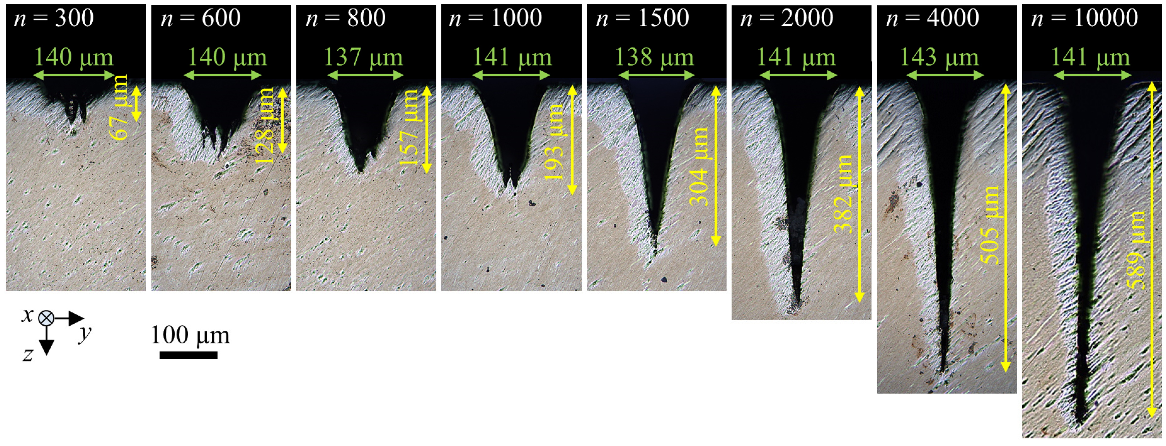
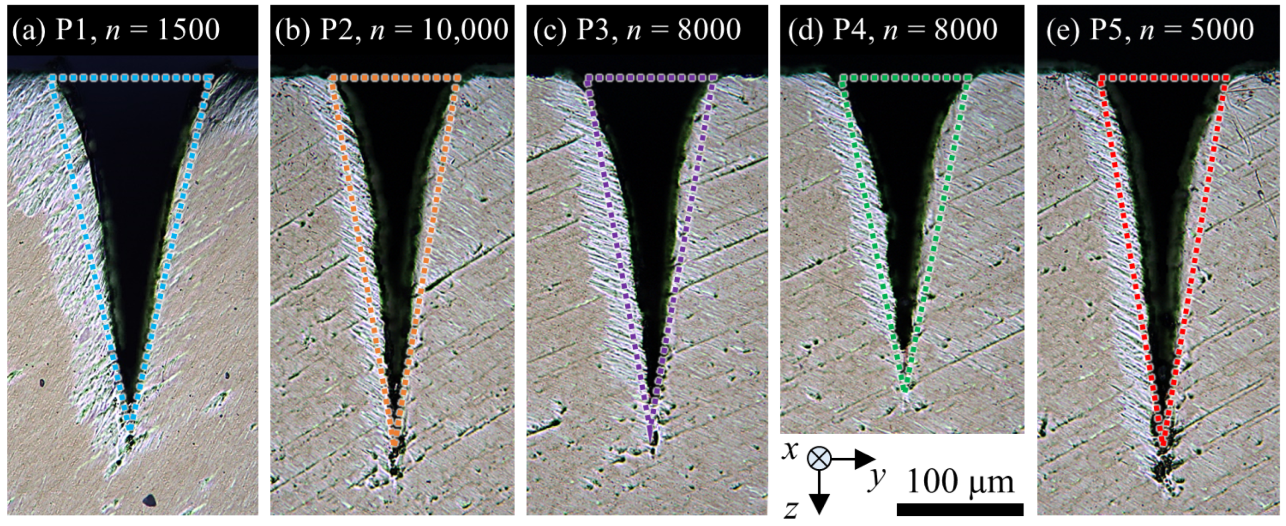
Figure 3 shows the cross sections obtained with the parameter set P1 (cf.
Table 1).
Five grooves were machined with each of the parameter sets listed in
Table 1. The measured values of the depth and width of the five grooves from each parameter set were used for averaging and calculating the maximum and minimum deviation. As expected from theory, the width of the groove remained constant at the value of
dG =
μm independent of the number of scans, which is also in good agreement with the results shown in [
2]. The V-shape clearly dominates the shape of the shown grooves for
n ≥ 800. Deviations from the V-shape can be seen for
n = 300 and
n = 600 due to rough structures at the bottom of the grooves. Bending of the tip of the groove occurred for
n = 10,000, which was also observed in [
8] for micromachining of deep grooves in a Ni-alloy and drilling of deep microholes in CVD diamond [
27]. The cause for the bending of the tip has not been conclusively clarified yet, but a polarization-dependent behaviour was found in [
27].
The material parameters for titanium published in [
28,
29] were used for the calculation of the volume-specific enthalpy of
hV = 47.1 J/mm³, which is required to heat and vaporize the material. The values are listed in
Table 2. The absorptivity of titanium at normal incidence and at a wavelength of 1030 nm was set to
A = 0.51 [
30]. The effective penetration depth was used as a fit parameter. A good agreement between the calculated and the experimental results was found with
lE = 30 nm. This value corresponds to an absorbed threshold fluence of
ϕth = 0.14 J/cm² (cf. Equation (3)). The fitted value of
lE = 30 nm is consistent with experimentally determined values of the optical penetration depth of 26 nm for Ti6Al4V [
31] and 30 nm for titanium [
22].
The groove widths are given by Equation (4) for the peak fluences of 3.81 J/cm² (P1) and 1.45 J/cm² (P2) yield dG = 126 µm and dG = 100 µm, respectively. The experimentally determined widths of µm (P1) and µm (P2) are slightly larger. The moderate deviations of less than 15% may be explained by the fact that no incubation effect is taken into account in the model.
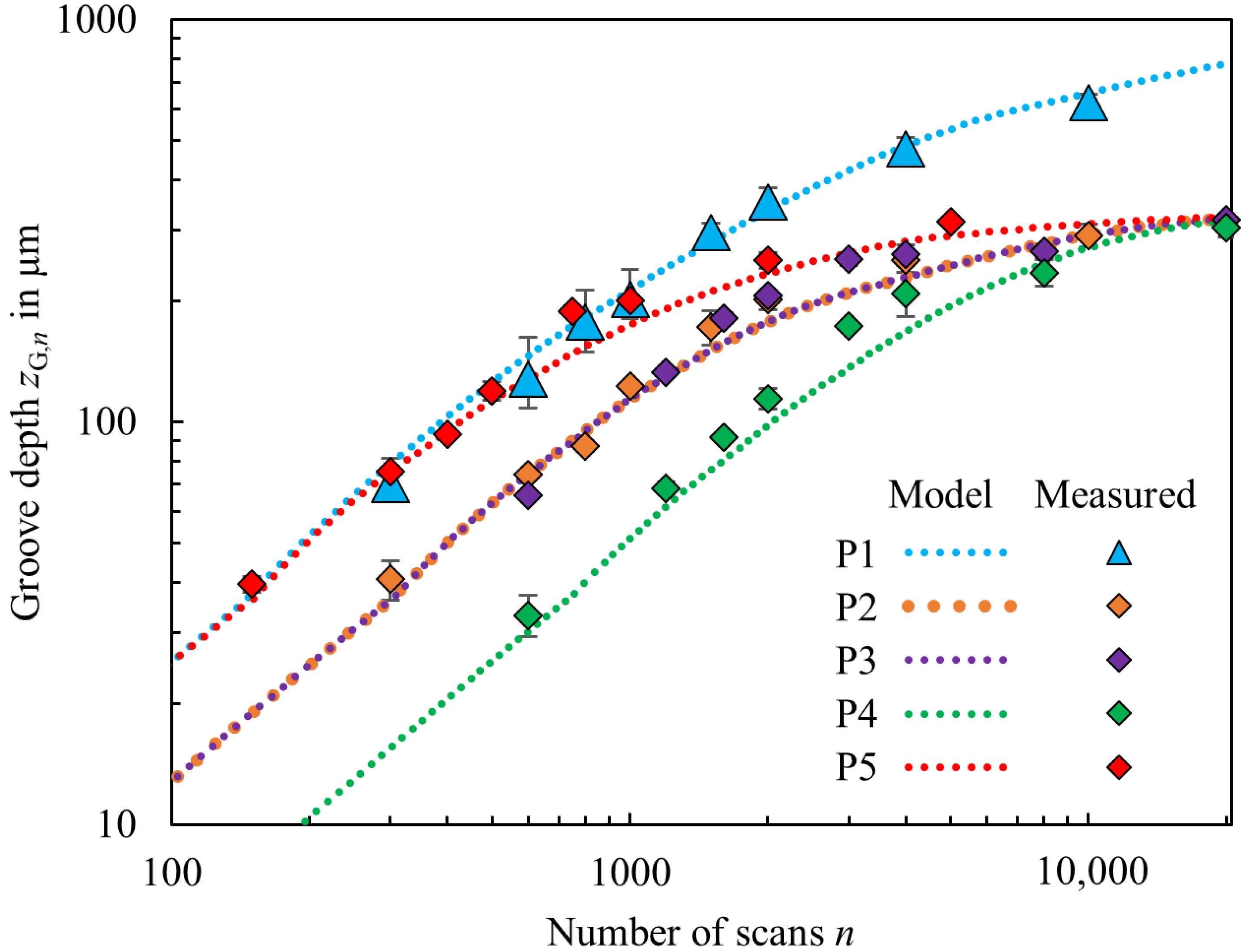
The progress of the groove depth
zG,n as a function of the number
n of scans was recursively calculated as described above. The calculations are compared to the experimental results in
Figure 4. The groove depths as calculated by the model derived in the previous section and as measured from the cross sections for the different parameter combinations P1–P5 (cf.
Table 1) are represented in different colors with dotted lines and data points, respectively. The value of the data points corresponds to the average values measured from up to five grooves micromachined with identical parameters. The error bars represent the deviation to the maximum and minimum measured groove depth of each parameter set.
Up to an aspect ratio (depth/width) of
zG/
dG ≈ 1.5, the measured groove depth increases almost linearly with the number of scans. The progress of the depth is found to slow down for aspect ratios beyond
zG/
dG > 1.5. At constant repetition rate
frep and scanning speed
vx, higher depth progress and deeper grooves were achieved for higher pulse energies (cf. P1 and P2). For constant pulse energy
EP and constant pulse overlap Ω
x, the groove depth as a function of number of scans is similar (cf. P2 and P3). However, the net processing time is divided in half for P3 in comparison to P2 due to double the scanning speed
vx at a twofold repetition rate
frep. At constant pulse energy
EP and constant repetition rate
frep, higher depth progress is achieved with lower scanning speeds
vx (cf. P3, P4 and P5). The relations observed in this work regarding the depth progress in micromachining of grooves in Ti6Al4V confirm the observations made for semiconductors in [
2,
9] and for a Ni-alloy in [
8]: The groove depth increases with increasing number of scans, and at high pulse energies and low scanning speeds, a greater increase in depth was observed with each scan. The maximum groove depth of
µm was achieved with the highest investigated pulse energy
EP = 181 µJ and the highest number of scans
n = 10,000 for this parameter combination (P1). The maximum measured groove depth for a constant pulse energy
EP = 69 µJ and different scanning parameters (from P2 to P5) is in the range of
µm.
The groove depths as calculated by the model (dotted lines, “Model”) and as measured by the cross sections with the optical microscope (data points, “Measured”) are in very good agreement for the different parameter combinations and for the different number of scans. The depth progress predicted by the model decreases with increasing number of scans and stagnates when the fluence in the tip converges the ablation threshold, which corresponds well with the results from [
2]. As a result, the calculated groove depths as a function of the number of scans for a constant pulse energy
EP = 69 µJ, but micromachined with different scanning parameters (from P2 to P5) converge to the same maximum groove depth, which agrees well with the theoretical prediction of the model of 326 µm calculated by Equation (16) for
η∞ = 1. Deviations from calculation and measurement might result from uncertainties regarding the material parameters used for the calculation, in particular the fitted value for the effective penetration depth
lE, or from deviations of the assumed ideal V-shape, as shown before in
Figure 3 for
n = 10,000, with the bending of the tip. Complete vaporization is assumed in the proposed analytical model, whereas additional effects such as melting and spallation can cause a deviating process enthalpy and thus a different ablation rate [
32].
Nevertheless, for a broad range of laser and scanning parameters, the V-shape and calculated groove dimensions by the model correspond to the shape and groove dimensions as measured by the cross sections shown in
Figure 5 for some of the grooves from P1 to P5 and different number of scans. The colored triangles were dimensioned according to the groove depth
zG and groove width
dG, as calculated by the model derived in the previous section.
Knowing the laser parameters EP and frep, the scanning speed vx and beam radius w0, and the three material parameters A, lE and hV, the model allows for the prediction of the groove dimensions as a function of the number of scans n and maximum achievable groove depth.


