
Rapid Customization and Manipulation Mechanism of Micro-Droplet Chip for 3D Cell Culture
Abstract
1. Introduction
2. Materials and Methods
2.1. Materials
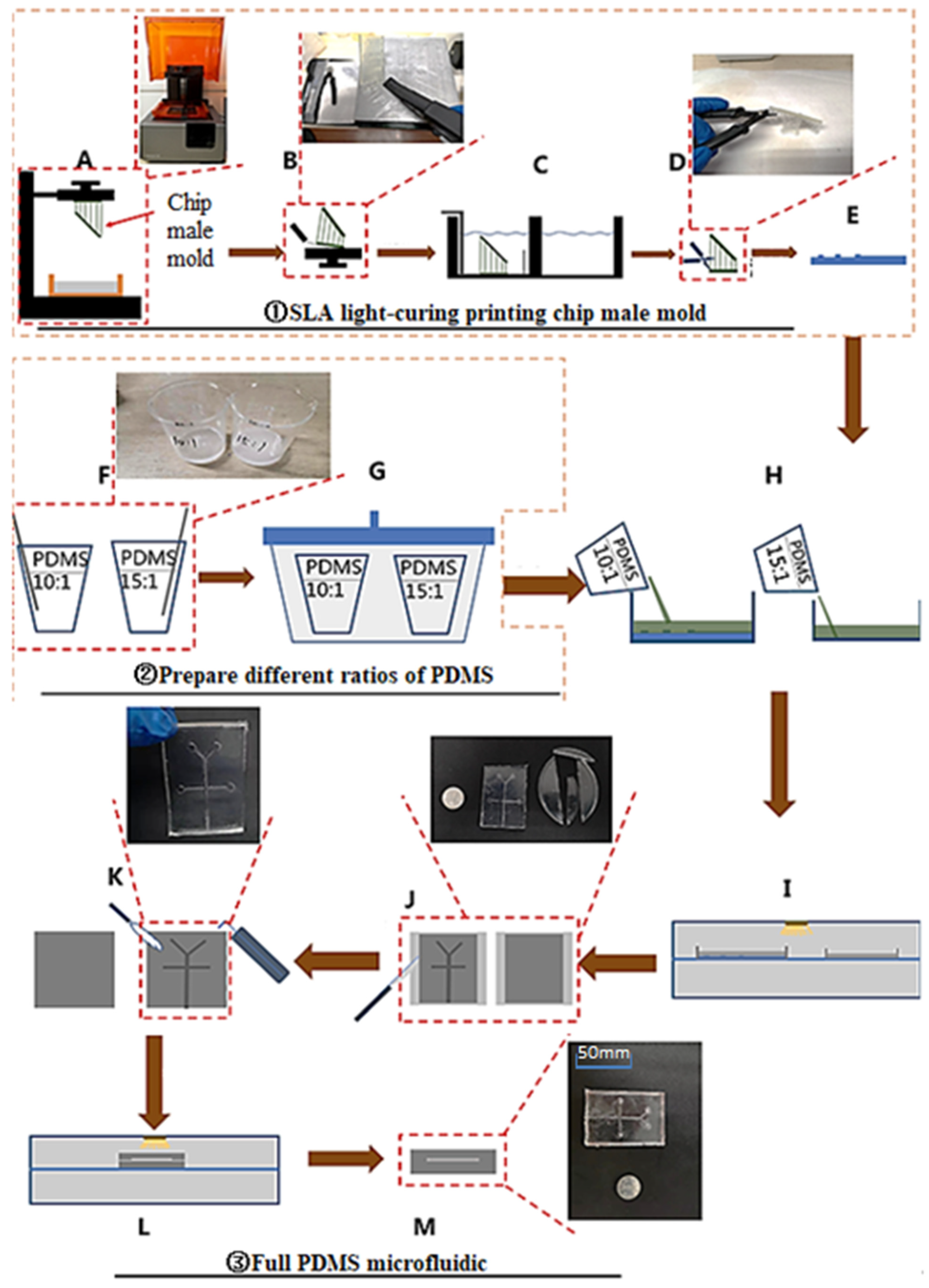
2.2. Fabrication
- (1)
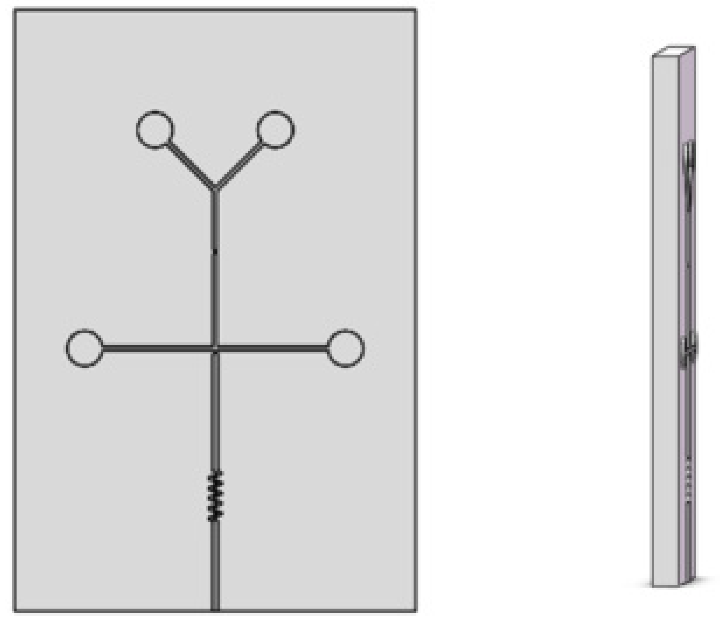
- Modeling of chip convex mold
- (2)
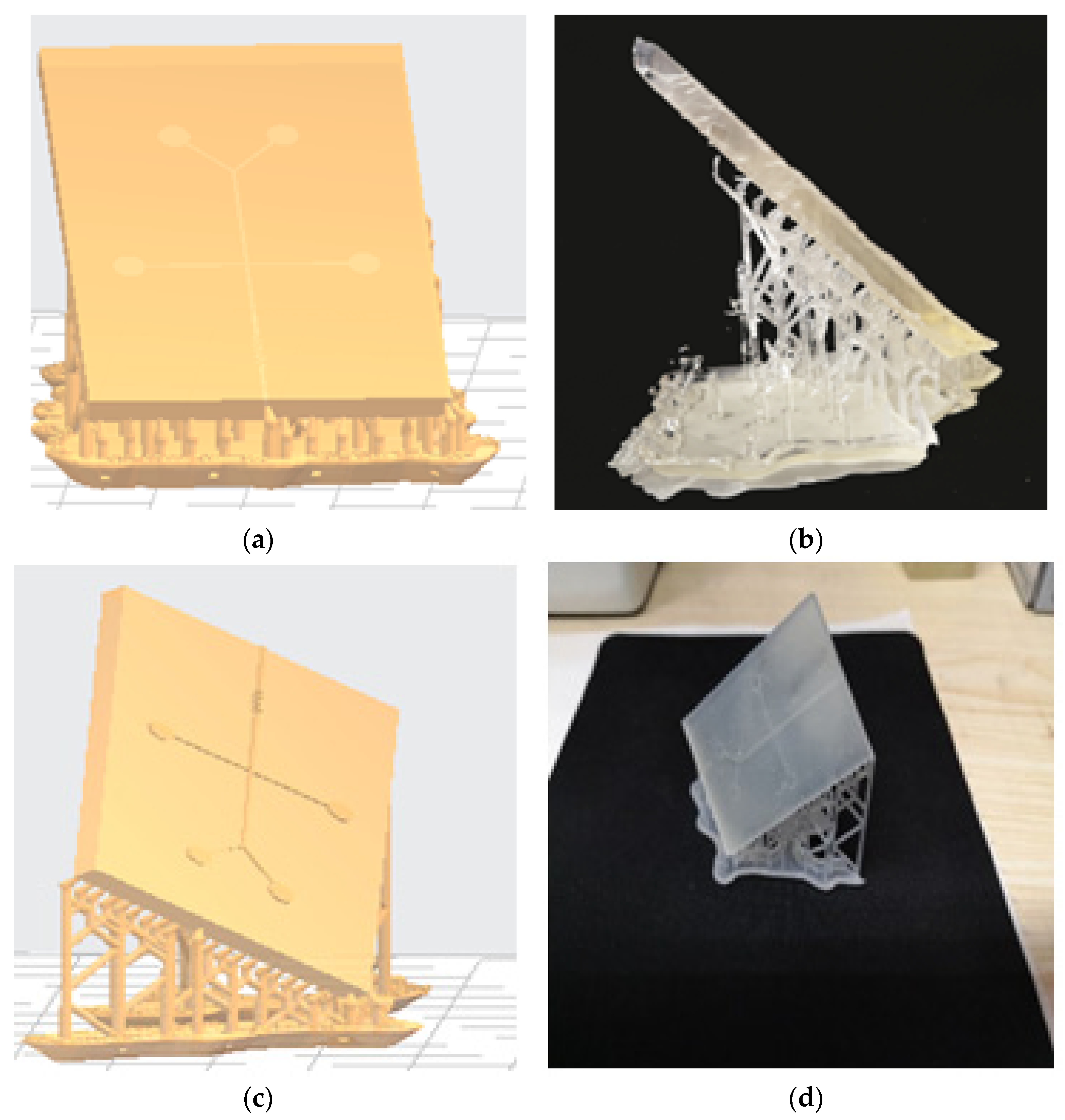
- Parameters setting and printing
- The principle of 45° angle;
- The principle of least support;
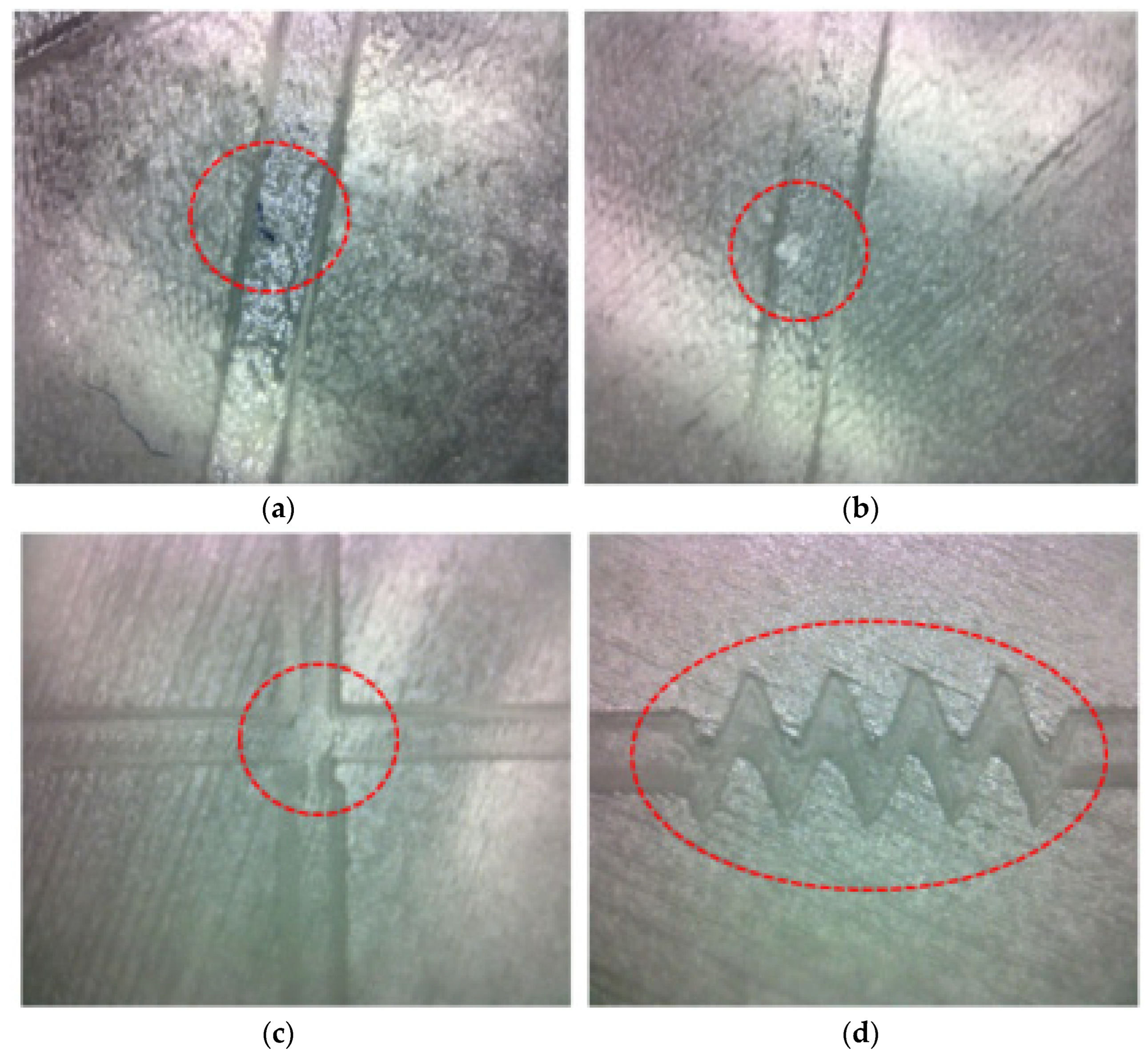
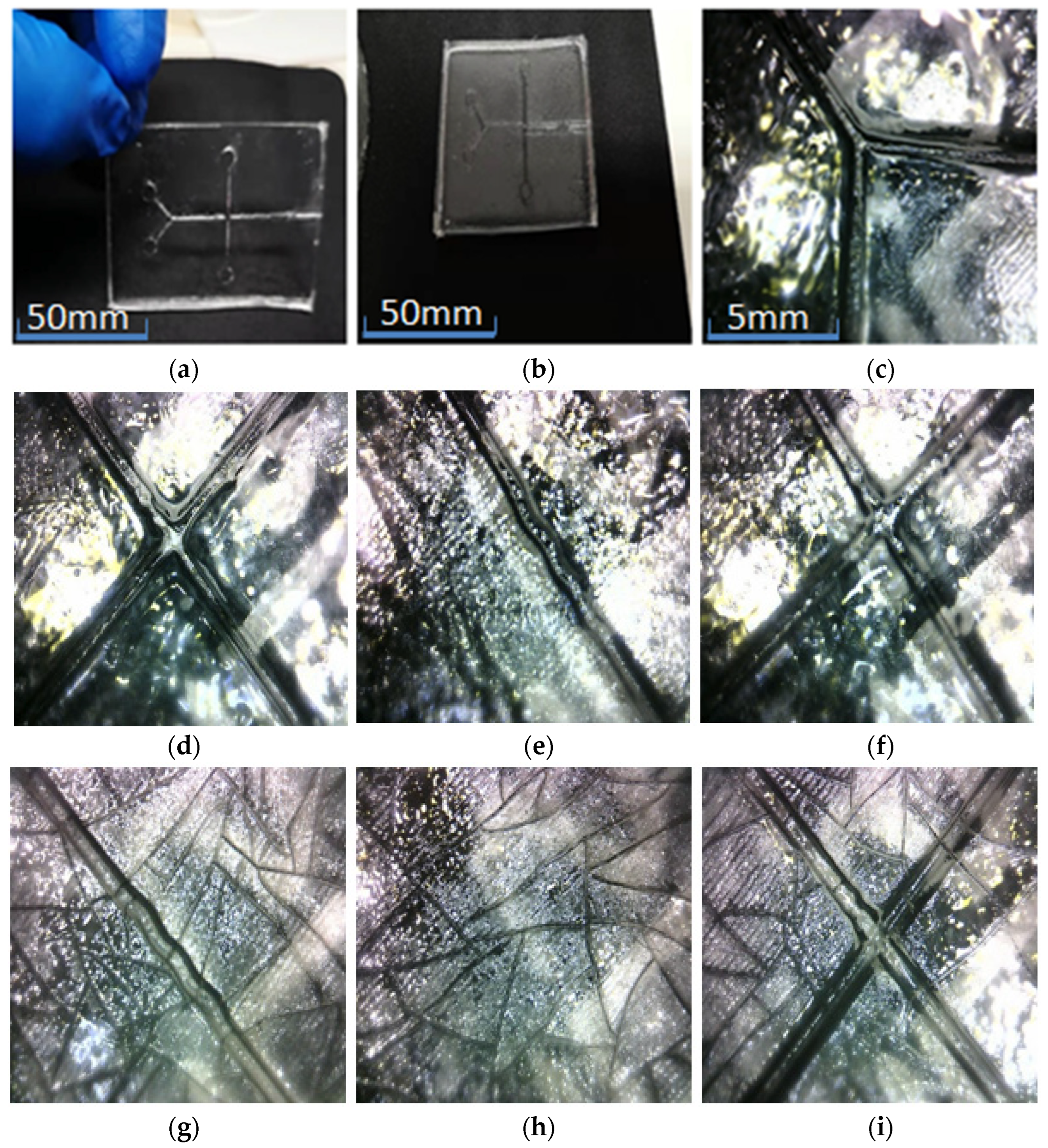
- The principle of single-angle start. Combining the above three principles, taking into account the subsequent requirements of the chip microchannel pouring Bonding re-quires surface roughness and transparency. It is not advisable to add too many sup-ports to the chip support plane. Therefore, we choose a cylindrical support with a den-sity of 100% and a printing inclination of 60° for chip printing (Figure 3).
- (3)
- Post-printing processing
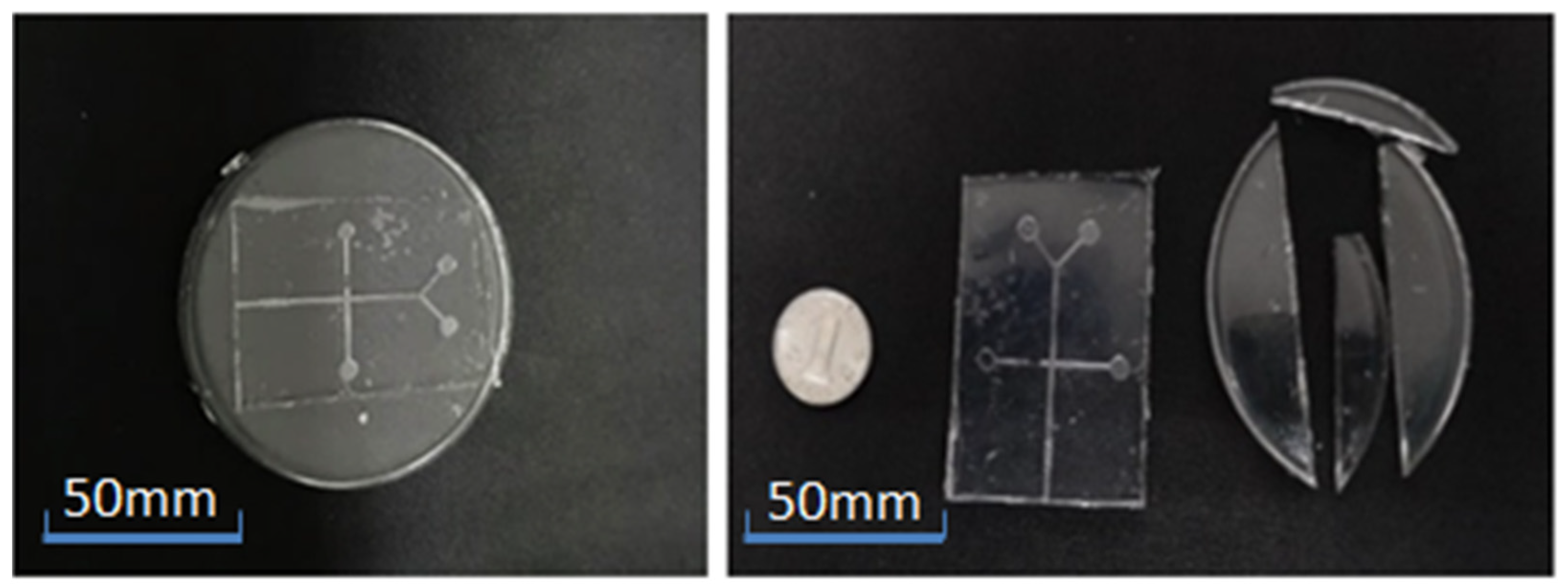
- (4)
- Finished product on the surface of the substrate convex mold.
2.3. Casting of Full PDMS Micro-Droplet Chip
- (1)
- Preparation of the mold
- (2)
- The ratio and mixing of PDMS and curing agent
- (3)
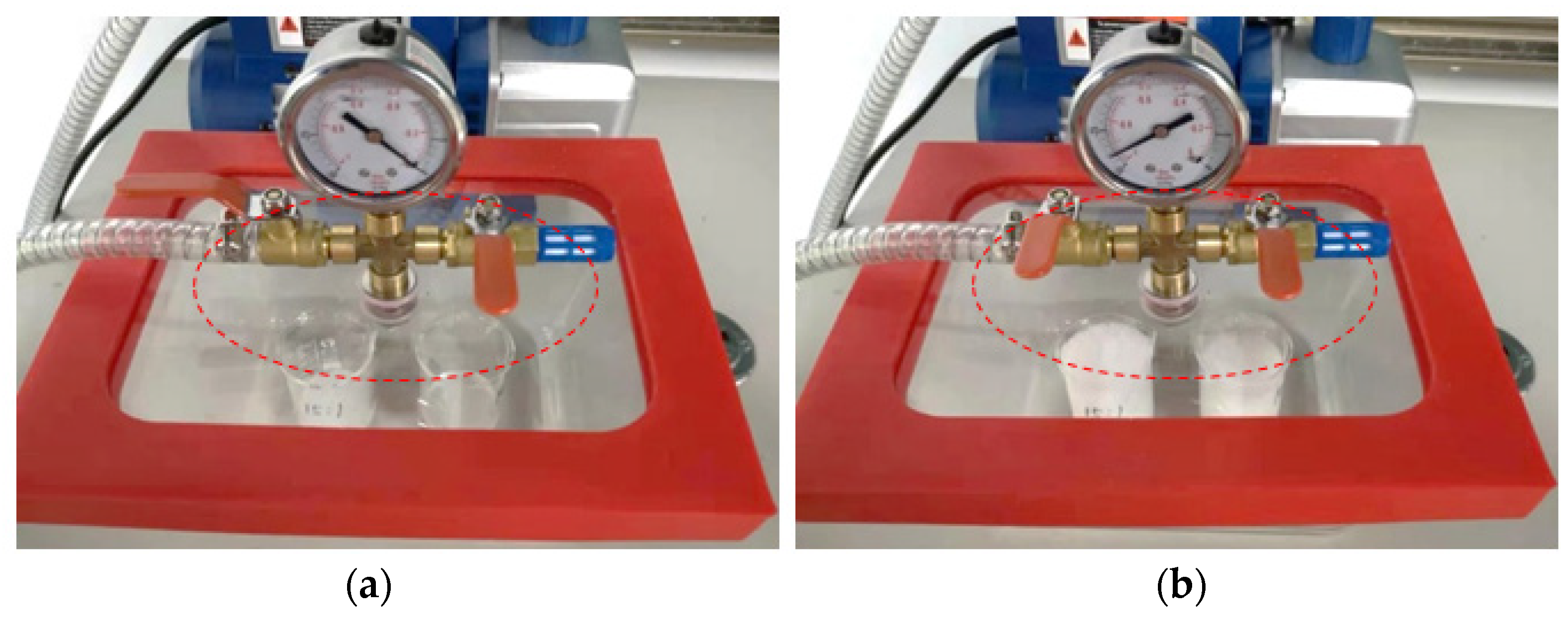
- Degassing to remove bubbles
- (4)
- Pouring PDMS on the mold
- (5)
- PDMS cutting and punching.
- (6)
- PDMS baking and stripping mold
- (7)
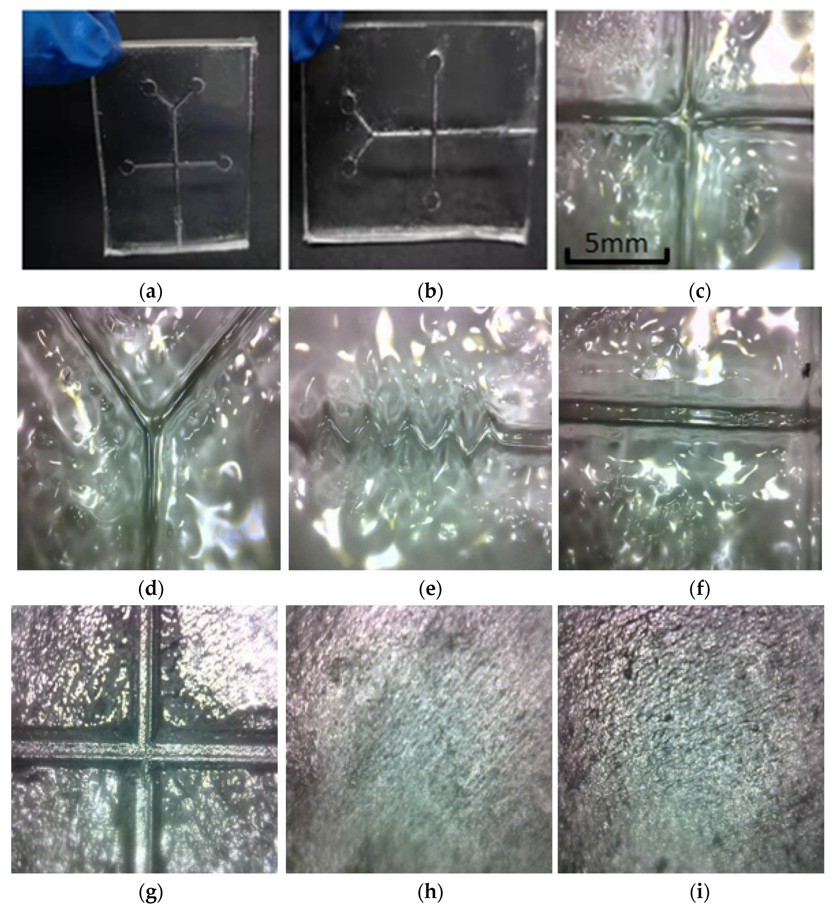
- Bonding of PDMS chip
3. Experiments and Results
4. Conclusions
Author Contributions
Funding
Data Availability Statement
Conflicts of Interest
References
- Loessberg-Zahl, J.; Beumer, J.; van den Berg, A.; Eijkel, J.C.T.; van der Meer, A.D. Patterning Biological Gels for 3D Cell Culture inside Microfluidic Devices by Local Surface Modification through Laminar Flow Patterning. Micromachines 2020, 11, 1112. [Google Scholar] [PubMed]
- Yang, T.; Peng, J.; Shu, Z.; Sekar, P.K.; Li, S.; Gao, D. Determination of the Membrane Transport Properties of Jurkat Cells with a Microfluidic Device. Micromachines 2019, 10, 832. [Google Scholar] [PubMed]
- Zhang, X.Y.; Sun, K.; Abulimiti, A.; Xu, P.P.; Li, Z.Y. Microfluidic System for Observation of Bacterial Culture and Effects on Biofilm Formation at Microscale. Micromachines 2019, 10, 606. [Google Scholar] [CrossRef] [PubMed]
- Wang, A.; Abdulla, A.; Ding, X. Micro-droplets-on-chip: A Review. J. Eng. Med. 2019, 233, 683–694. [Google Scholar]
- Nam, U.; Kim, S.; Park, J.; Jeon, J.S. Lipopolysaccharide-Induced Vascular Inflammation Model on Microfluidic Chip. Micromachines 2020, 11, 747. [Google Scholar]
- Mao, S.; Gao, D.; Liu, W.; Wei, H.; Lin, J.M. Imitation of drug metabolism in human liver and cytotoxicity assay using a microfluidic device coupled to mass spectrometric detection. Lab. Chip 2012, 12, 219–226. [Google Scholar] [CrossRef]
- Gao, D.; Liu, H.; Lin, J.M.; Wang, Y.; Jiang, Y. Characterization of drug permeability in Caco-2 monolayers by mass spectrometry on a membrane-based microfluidic device. Lab. Chip 2013, 13, 978–985. [Google Scholar]
- Wei, H.; Li, H.; Gao, D.; Lin, J.M. Multi-channel microfluidic devices combined with electrospray ionization quadrupole time-of-flight mass spectrometry applied to the monitoring of glutamate release from neuronal cells. Analyst 2010, 135, 2043–2050. [Google Scholar]
- Wufuer, M.; Lee, G.; Hur, W.; Jeon, B.; Kim, B.J.; Choi, T.H.; Lee, S. Skin-on-a-chip model simulating inflammation, edema and drug-based treatment. Sci. Rep. 2016, 6, 37471. [Google Scholar]
- Pal, R.; Mamidi, M.K.; Das, A.K.; Bhonde, R. Comparative analysis of cardiomyocyte differentiation from human embryonic stem cells under 3-D and 2-D culture conditions. J. Biosci. Bioeng. 2013, 115, 200–206. [Google Scholar] [CrossRef]
- Leclerc, E.; David, B.; Griscom, L.; Lepioufle, B.; Fujii, T.; Layrolle, P.; Legallaisa, C. Study of osteoblastic cells in a microfluidic environment. Biomaterials 2006, 27, 586–595. [Google Scholar] [CrossRef] [PubMed]
- Lii, J.; Hsu, W.J.; Parsa, H.; Das, A.; Rouse, R.; Sia, S.K. Real-time microfluidic system for studying mammalian cells in 3D microenvironments. Anal. Chem. 2008, 80, 3640–3647. [Google Scholar] [CrossRef]
- Chung, S.; Sudo, R.; Mack, P.J.; Wan, C.R.; Vickerman, V.; Kamm, R.D. Cell migration into scaffolds under co-culture conditions in a microfluidic platform. Lab. Chip 2009, 9, 269–275. [Google Scholar] [CrossRef] [PubMed]
- Tumarkin, E.; Tzadu, L.; Csaszar, E.; Seo, M.; Zhang, H.; Lee, A.; Peerani, R.; Purpura, K.; Zandstra, P.W.; Kumacheva, E. High-throughput combinatorial cell co-culture using microfluidics. Integr. Biol. 2011, 3, 653–662. [Google Scholar] [CrossRef] [PubMed]
- Tsuda, Y.; Morimoto, Y.; Takeuchi, S. Monodisperse cell-encapsulating peptide microgel beads for 3D cell culture. Langmuir 2010, 26, 2645–2649. [Google Scholar] [CrossRef] [PubMed]
- Liu, J.; Gao, D.; Li, H.F.; Lin, J.M. Controlled photopolymerization of hydrogel microstructures inside microchannels for bioassays. Lab. Chip 2009, 9, 1301–1305. [Google Scholar] [CrossRef] [PubMed]
- Wu, J.; Chen, Q.; Liu, W.; Zhang, Y.; Lin, J.M. Cytotoxicity of quantum dots assay on a microfluidic 3D-culture device based on modeling diffusion process between blood vessels and tissues. Lab Chip 2012, 12, 3474–3480. [Google Scholar] [CrossRef]
- Ong, S.M.; Zhang, C.; Toh, Y.C.; Kim, S.H.; Foo, H.L.; Tan, C.H.; van Noort, D.; Park, S.; Yu, H. A gel-free 3D microfluidic cell culture system. Biomaterials 2008, 29, 3237–3244. [Google Scholar]
- Toh, Y.C.; Zhang, C.; Zhang, J.; Khong, Y.M.; Chang, S.; Samper, V.D.; van Noort, D.; Hutmacher, D.W.; Yu, H. A novel 3D mammalian cell perfusion-culture system in microfluidic channels. Lab. Chip 2007, 7, 302–309. [Google Scholar] [CrossRef] [PubMed]
- Choi, J.; Kim, S.; Jung, J.; Lim, Y.; Kang, K.; Park, S.; Kang, S. Wnt 5a-mediating neurogenesis of human adipose tissue-derived stem cells in a 3D microfluidic cell culture system. Biomaterials 2011, 32, 7013–7022. [Google Scholar] [CrossRef] [PubMed]
- Toh, Y.C.; Lim, T.C.; Tai, D.; Xiao, G.; van Noort, D.; Yu, H. A microfluidic 3D hepatocyte chip for drug toxicity testing. Lab. Chip 2009, 9, 2026–2035. [Google Scholar] [CrossRef] [PubMed]
- Ruiz, C.; Kadimisetty, K.; Yin, K.; Mauk, M.G.; Zhao, H.; Liu, C. Fabrication of Hard-Soft Microfluidic Devices Using Hybrid 3D Printing. Micromachines 2020, 11, 567. [Google Scholar] [CrossRef] [PubMed]
- Dash, S.; Chandramohan, A.; Weibel, J.A.; Garimella, S.V. Buoyancy-induced on-the-spot mixing in droplets evaporating on nonwetting surfaces. Phys. Rev. E Stat. Nonlin. Soft Matter. Phys. 2014, 90, 062407. [Google Scholar] [CrossRef] [PubMed]
- Anna, S.L.; Bontoux, N.; Stone, H.A. Formation of dispersions using “flow focusing” in microchannels. Appl. Phys. Lett. 2003, 82, 364–366. [Google Scholar] [CrossRef]
- Garstecki, P.; Gitlin, I.; DiLuzio, W.; Whitesides, G.M.; Kumacheva, E.; Stone, H.A. Formation of monodisperse bubbles in a microfluidic flow-focusing device. Appl. Phys. Lett. 2004, 85, 2649–2651. [Google Scholar] [CrossRef]
- Cramer, C.; Fischer, P.; Windhab, E.J. Drop formation in a co-flowing ambient fluid. Chem. Eng. Sci. 2004, 59, 3045–3058. [Google Scholar] [CrossRef]
- Singh, P.; Aubry, N. Transport and deformation of droplets in a microdevice using dielectrophoresis. Electrophoresis 2007, 28, 644–657. [Google Scholar]
- Schwartz, J.A.; Vykoukal, J.V.; Gascoyne, P.R. Droplet-based chemistry on a programmable micro-chip. Lab. Chip 2004, 4, 11–17. [Google Scholar] [CrossRef]
- Wang, Q.; Yuan, D.; Li, W. Analysis of Hydrodynamic Mechanism on Particles Focusing in Micro-Channel Flows. Micromachines 2017, 8, 197. [Google Scholar] [CrossRef]
- Duffy, D.C.; McDonald, J.C.; Schueller, O.J.; Whitesides, G.M. Rapid Prototyping of Microfluidic Systems in Poly(dimethylsiloxane). Anal. Chem. 1998, 70, 4974–4984. [Google Scholar]
- Unger, M.A.; Chou, H.P.; Thorsen, T.; Scherer, A.; Quake, S.R. Monolithic microfabricated valves and pumps by multilayer soft lithography. Science 2000, 288, 113–116. [Google Scholar] [PubMed]


| Properties | Fluid 1 | Fluid 2 |
|---|---|---|
| Viscosity (pa.s) | 0.6 | 0.671 |
| Density (g/mL) | 1.5 | 0.877 |
| Interfacial tension (n/m) | 0.03 | 0.03 |
| Contact angle | 135° | 135° |
Publisher’s Note: MDPI stays neutral with regard to jurisdictional claims in published maps and institutional affiliations. |
© 2022 by the authors. Licensee MDPI, Basel, Switzerland. This article is an open access article distributed under the terms and conditions of the Creative Commons Attribution (CC BY) license (https://creativecommons.org/licenses/by/4.0/).
Share and Cite
Liu, H.; Yang, C.; Wang, B. Rapid Customization and Manipulation Mechanism of Micro-Droplet Chip for 3D Cell Culture. Micromachines 2022, 13, 2050. https://doi.org/10.3390/mi13122050
Liu H, Yang C, Wang B. Rapid Customization and Manipulation Mechanism of Micro-Droplet Chip for 3D Cell Culture. Micromachines. 2022; 13(12):2050. https://doi.org/10.3390/mi13122050
Chicago/Turabian StyleLiu, Haiqiang, Chen Yang, and Bangbing Wang. 2022. "Rapid Customization and Manipulation Mechanism of Micro-Droplet Chip for 3D Cell Culture" Micromachines 13, no. 12: 2050. https://doi.org/10.3390/mi13122050
APA StyleLiu, H., Yang, C., & Wang, B. (2022). Rapid Customization and Manipulation Mechanism of Micro-Droplet Chip for 3D Cell Culture. Micromachines, 13(12), 2050. https://doi.org/10.3390/mi13122050