
Analyzing Distributed Vibrating Sensing Technologies in Optical Meshes

 , , , ,
  ,
, 
Abstract
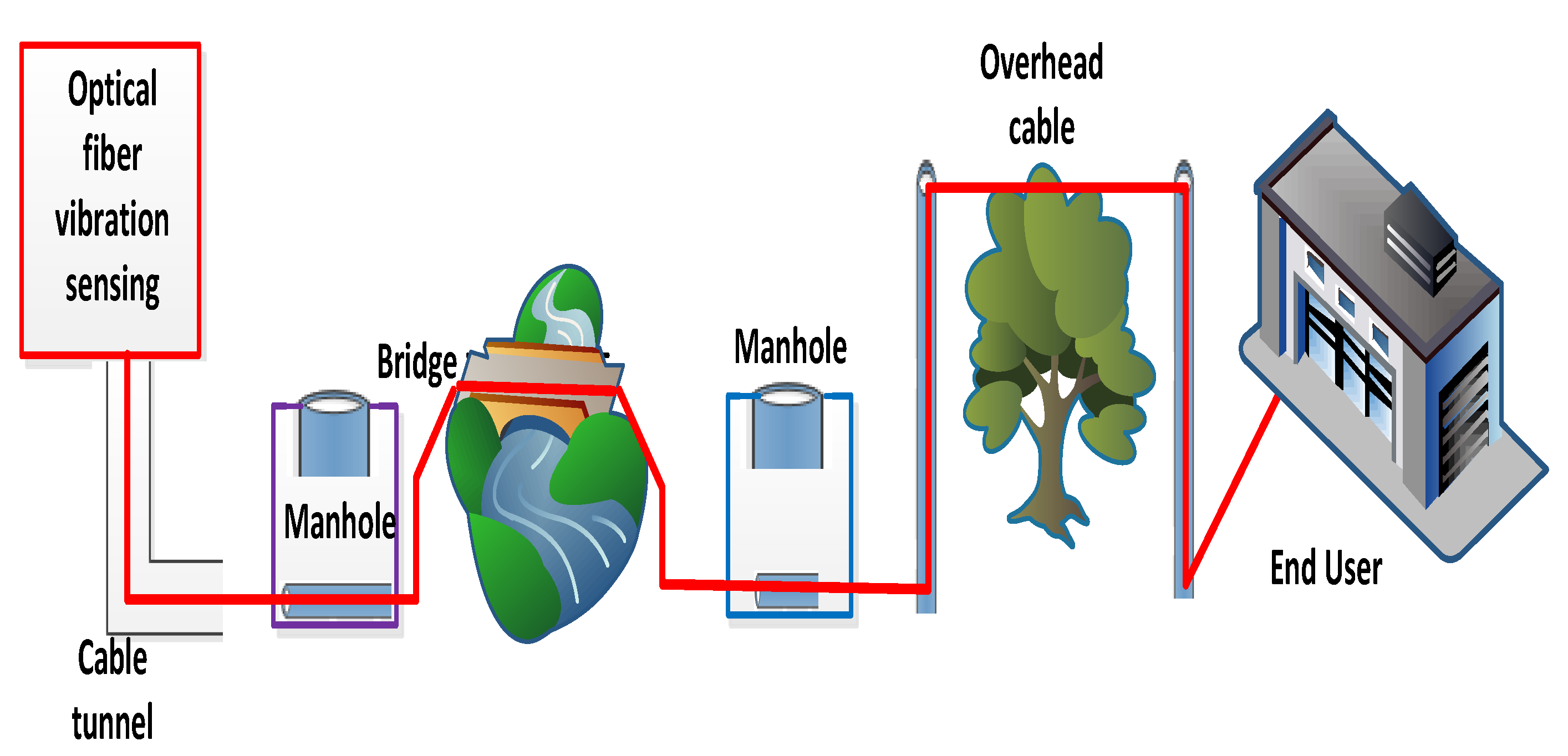
:1. Introduction
1.1. Motivation
1.2. Major Contribution
- DVS measurement technologies are proposed for visualizing the state of the optical fiber;
- The significant drawbacks of OFDR, like the low repetition rate of the probe light and short measurement range, are addressed in this paper;
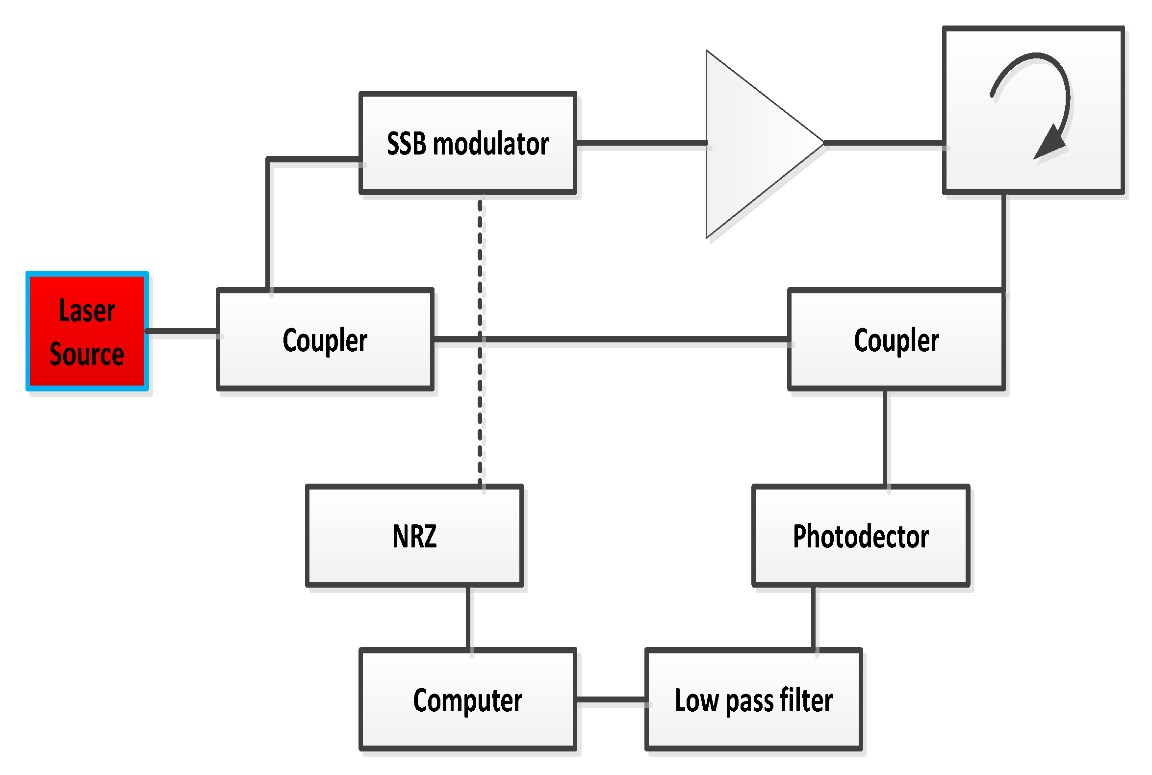
- The single-sideband modulation through a microwave signal generator is applied to manage the repetition rate, and relative distance estimations are used to improve distance measurements;
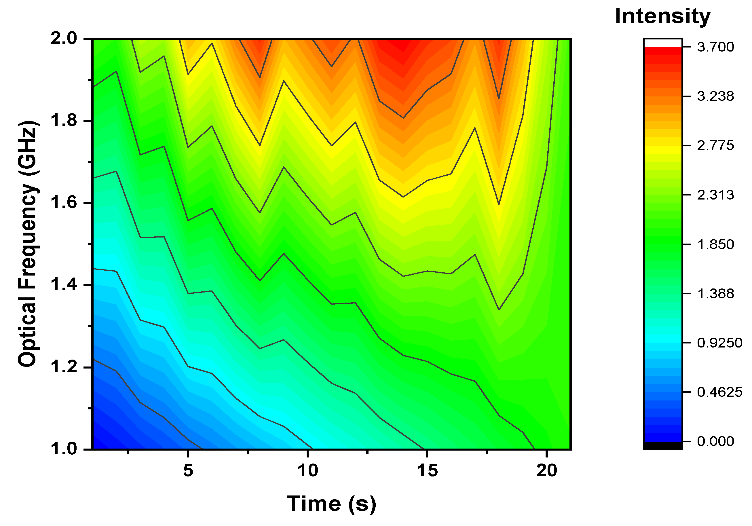
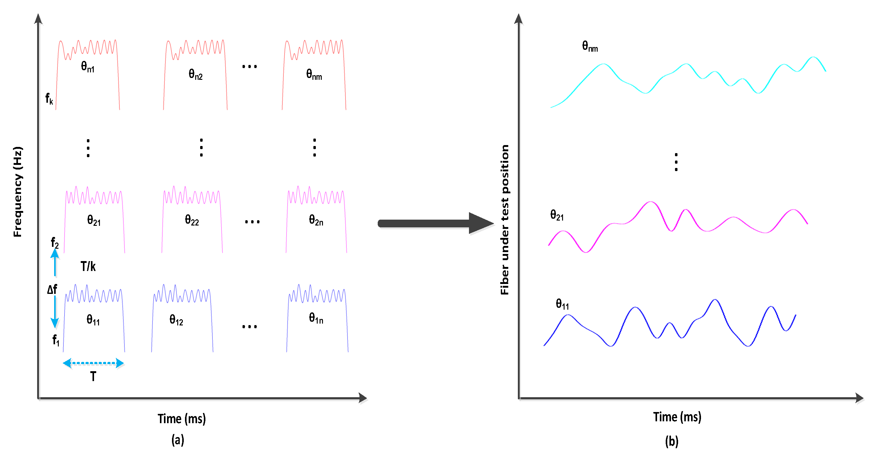
- The analytical analysis of the proposed model is investigated in terms of short-time Fourier transform (STFT), optical frequency, laser phase noise, backscattered signal light and fiber range.
1.3. Comparative Distance Computation Using OFDR
1.4. Organization and Notaion of Paper
2. Discussion
3. Conclusions
Author Contributions
Funding
Institutional Review Board Statement
Data Availability Statement
Conflicts of Interest
References
- Posey, R., Jr.; Johnson, G.A.; Vohra, S.T. Strain sensing based on coherent Rayleigh scattering in an optical fibre. Electron. Lett. 2000, 36, 1688–1689. [Google Scholar] [CrossRef]
- Masoudi, A.; Belal, M.; Newson, T.P. A distributed optical fibre dynamic strain sensor based on phase-OTDR. Meas. Sci. Technol. 2013, 24, 085204. [Google Scholar] [CrossRef]
- Pastor-Graells, J.; Martins, H.F.; Garcia-Ruiz, A.; Martin-Lopez, S.; Gonzalez-Herraez, M. Single-shot distributed temperature and strain tracking using direct detection phase-sensitive OTDR with chirped pulses. Opt. Exp. 2016, 24, 13121–13133. [Google Scholar] [CrossRef]
- Lu, Y.; Zhu, T.; Chen, L.; Bao, X. Distributed vibration sensor based on coherent detection of phase-OTDR. IEEE J. Light. Technol. 2010, 28, 3243–3249. [Google Scholar]
- Liehr, S.; Munzenberger, S.; Krebber, K. Wavelength-scanning coherent OTDR for dynamic high strain resolution sensing. Opt. Exp. 2018, 26, 10573–10588. [Google Scholar] [CrossRef] [PubMed]
- Wang, S.; Fan, X.; Liu, Q.; He, Z. Distributed fiber-optic vibration sensing based on phase extraction from time-gated digital OFDR. Opt. Exp. 2015, 23, 33301–33309. [Google Scholar] [CrossRef] [PubMed]
- Peng, F.; Duan, N.; Rao, Y.; Li, J. Real-time position and speed monitoring of trains using phase-sensitive OTDR. IEEE Photon. Technol. Lett. 2014, 26, 2055–2057. [Google Scholar] [CrossRef]
- Wu, H.; Chen, J.; Xial, X.L.Y.; Wang, M.; Zheng, Y.; Rao, Y. One-dimensional CNN-based intelligent recognition of vibrations in pipeline monitoring with DAS. IEEE J. Light. Technol. 2019, 37, 4359–4366. [Google Scholar] [CrossRef]
- Owen, A.; Duckworth, G.; Worsley, J. OptaSense: Fiber optic distributed acoustic sensing for border monitoring. In Proceedings of the Intell Security Information Conference, Kralendijk, Bonaire, 27 Februray–2 March 2012; pp. 362–364. [Google Scholar]
- Huang, M.; Salemi, M.; Chen, Y.; Zhao, J.; Xia, T.J.; Wellbrock, G.A.; Huang, Y.; Milione, G.; Ip, E.; Ji, P.; et al. First field trial of distributed fiber optical sensing and high-speed communication over an operational telecom network. IEEE J. Light. Technol. 2020, 38, 75–81. [Google Scholar] [CrossRef]
- Williams, E.F.; Fernadez-Ruiz, M.R.; Magalhaes, R.; Vanthillo, R.; Zhan, Z.; Gonzalez-Herraez, M.; Martins, H.F. Distributed sensing of microseisms and teleseisms with submarine dark fibers. Nat. Commun. 2019, 10, 5778. [Google Scholar] [CrossRef] [Green Version]
- Ajo-Franklin, J.B.; Dou, S.; Lindsey, N.J.; Monga, I.; Tracy, C.; Robertson, M.; Tribaldos, V.R.; Ulrich, C.; Freifeld, B.; Daley, T.; et al. Distributed acoustic sensing using dark fiber for near-surface characterization and broadband seismic event detection. Sci. Rep. 2019, 9, 1328. [Google Scholar] [CrossRef] [Green Version]
- Jousset, P.; Reinsch, T.; Ryberg, T.; Blanck, H.; Clarke, A.; Aghayev, R.; Hersir, G.; Henninges, J.; Webber, M.; Krawczyk, C.M. Dyanamic strain determination using fibre-optic cables allows imaging of seismological and structural features. Nat. Commun. 2018, 9, 2509. [Google Scholar] [CrossRef]
- Glombitza, U.; Brinkmeyer, E. Coherent frequency-domain reflectometry for characterization of single-mode integrated-optical waveguides. IEEE J. Light. Technol. 1993, 11, 1377–1384. [Google Scholar] [CrossRef]
- Froggatt, M.; Moore, J. High-spatial-resolution distributed strain measurement in optical fiber with Rayleigh scatter. Appl. Opt. 1998, 37, 1735–1740. [Google Scholar] [CrossRef] [PubMed]
- Okamoto, T.; Iida, D.; Oshida, H. Investigation of tolerance of OFDR-based DAS to vibration-induced beat frequency offset. In Proceedings of the OFC 2020, San Diego, CA, USA, 6–17 January 2020. [Google Scholar]
- Zhou, D.P.; Qin, Z.; Li, W.; Chen, L.; Bao, X. Distributed vibration sensing with time-resolved optical frequency-domain reflectometry. Opt. Exp. 2012, 20, 13138–13145. [Google Scholar] [CrossRef]
- Zhou, D.P.; Chen, L.; Bao, X. Distributed dynamic strain measurement using optical frequency-domain reflectometry. Appl. Opt. 2016, 55, 6735–6739. [Google Scholar] [CrossRef] [PubMed]
- Okamoto, T.; Iida, D.; Oshida, H. Vibration-induced beat frequency offset compensation in distributed acoustic sensing based on optical frequency domain reflectometry. J. Light. Technol. 2019, 37, 4896–4901. [Google Scholar] [CrossRef]
- Kim, Y.; Kim, M.J.; Rho, B.S.; Kim, Y.H. Measurement range enhancement of Rayleigh-based optical frequency domain reflectometry with bidirectional determination. IEEE Photon. J. 2017, 9. [Google Scholar] [CrossRef]
- Iida, D.; Honda, N.; Oshida, H. Advances in distributed vibration sensing for optical communication fiber state visualization. Opt. Fiber Technol. 2020, 57, 102263. [Google Scholar] [CrossRef]
- Xia, T.J.; Wellbrock, G.A.; Huang, M.; Salemi, M.; Chen, Y.; Wang, T.; Aono, A.Y. First proof that geographic location on deployed fiber cable can be determined by using OTDR distance based on distributed fiber optical sensing technology. In Proceedings of the Optical Fiber Communication Conference (OFC) 2020, San Diego, CA, USA, 8–12 March 2020. [Google Scholar]
- Okamoto, T.; Iida, D.; Oshida, H. Identification of sagging aerial cable section by distributed vibration sensing based on OFDR. In Proceedings of the Optical Fiber Communication Conference (OFC) 2019, San Diego, CA, USA, 3–7 March 2019. [Google Scholar]
- Irfan, M.; Ali, F.; Muhammad, F.; Habib, U.; Alwadie, A.S.; Glowacz, A.; Abbas, Z.H.; Kańtoch, E. DSP-Assisted Nonlinear Impairments Tolerant 100 Gbps Optical Backhaul Network for Long-Haul Transmission. Entropy 2020, 22, 1062. [Google Scholar] [CrossRef] [PubMed]
- Waksiaka, Y.; Iida, D.; Okamoto, K.; Oshida, H. Suppressing waveform distortion in phase-OTDR vibration sensing for visualizing optical fiber cable state. In Proceedings of the 45th European Conference on Optical Communication (ECOC 2019), Dublin, Ireland, 22–26 September 2019. [Google Scholar]
- Li, Z.; Tong, Y.; Fu, X.; Wang, J.; Guo, Q.; Yu, H.; Bao, X. Simultaneous distributed static and dynamic sensing based on ultra-short fiber Bragg gratings. Opt. Exp. 2018, 26, 17437–17446. [Google Scholar] [CrossRef] [PubMed]


Publisher’s Note: MDPI stays neutral with regard to jurisdictional claims in published maps and institutional affiliations. |
© 2022 by the authors. Licensee MDPI, Basel, Switzerland. This article is an open access article distributed under the terms and conditions of the Creative Commons Attribution (CC BY) license (https://creativecommons.org/licenses/by/4.0/).
Share and Cite
Rahman, S.; Ali, F.; Muhammad, F.; Irfan, M.; Glowacz, A.; Shahed Akond, M.; Armghan, A.; Faraj Mursal, S.N.; Ali, A.; Alkahtani, F.S. Analyzing Distributed Vibrating Sensing Technologies in Optical Meshes. Micromachines 2022, 13, 85. https://doi.org/10.3390/mi13010085
Rahman S, Ali F, Muhammad F, Irfan M, Glowacz A, Shahed Akond M, Armghan A, Faraj Mursal SN, Ali A, Alkahtani FS. Analyzing Distributed Vibrating Sensing Technologies in Optical Meshes. Micromachines. 2022; 13(1):85. https://doi.org/10.3390/mi13010085
Chicago/Turabian StyleRahman, Saifur, Farman Ali, Fazal Muhammad, Muhammad Irfan, Adam Glowacz, Mohammed Shahed Akond, Ammar Armghan, Salim Nasar Faraj Mursal, Amjad Ali, and Fahad Salem Alkahtani. 2022. "Analyzing Distributed Vibrating Sensing Technologies in Optical Meshes" Micromachines 13, no. 1: 85. https://doi.org/10.3390/mi13010085
APA StyleRahman, S., Ali, F., Muhammad, F., Irfan, M., Glowacz, A., Shahed Akond, M., Armghan, A., Faraj Mursal, S. N., Ali, A., & Alkahtani, F. S. (2022). Analyzing Distributed Vibrating Sensing Technologies in Optical Meshes. Micromachines, 13(1), 85. https://doi.org/10.3390/mi13010085