
Measurement of Small-Slope Free-Form Optical Surfaces with the Modified Phase Retrieval


Abstract
:1. Introduction
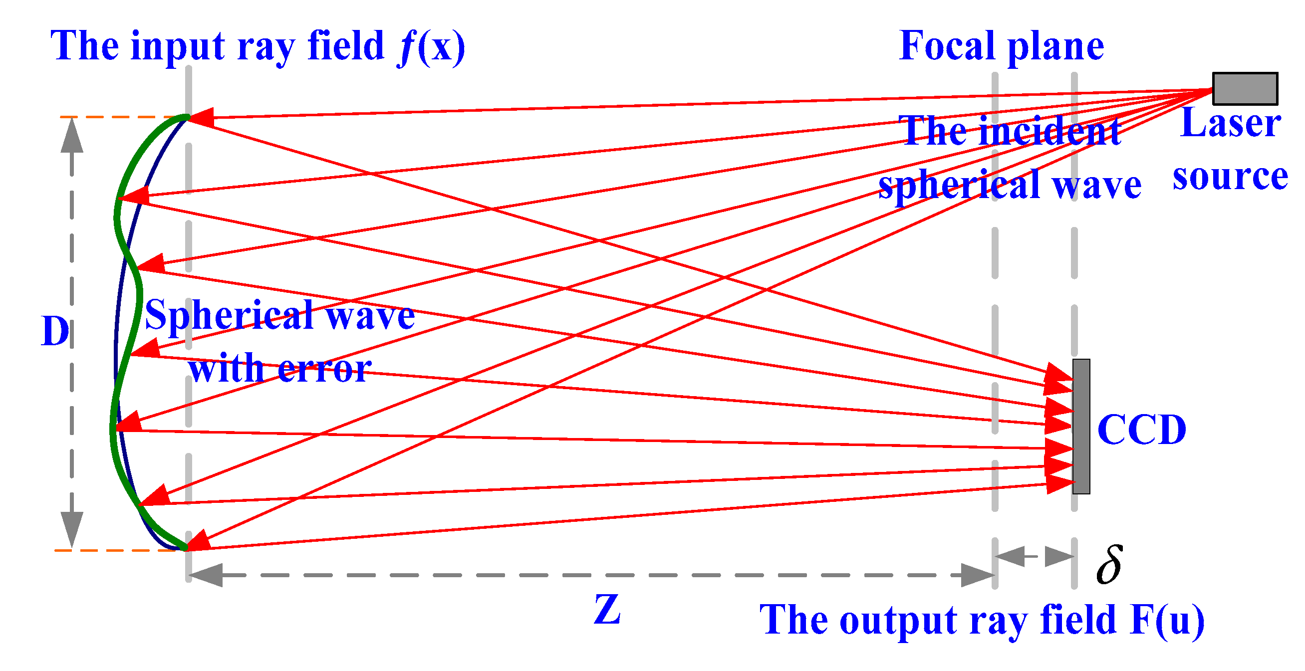
2. Theory of PR
2.1. The Principle of PR
2.2. The Modified Gradient Search Algorithm of PR
- , , , ,
- , ,
- , ,
- , ,
- , ,
- .
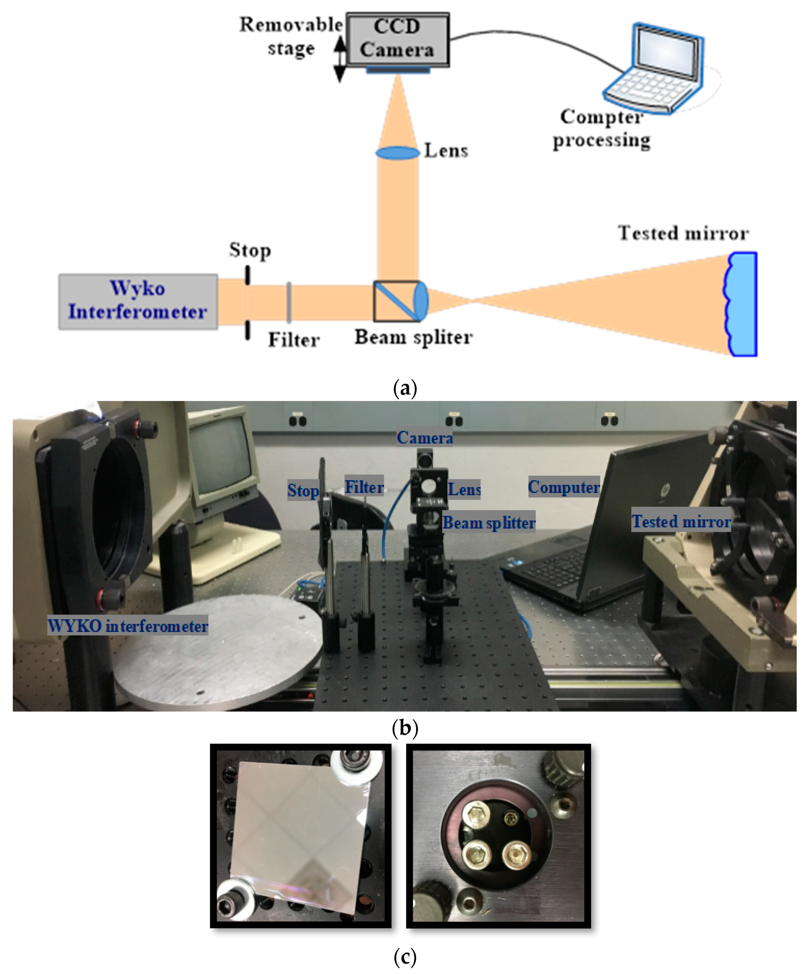
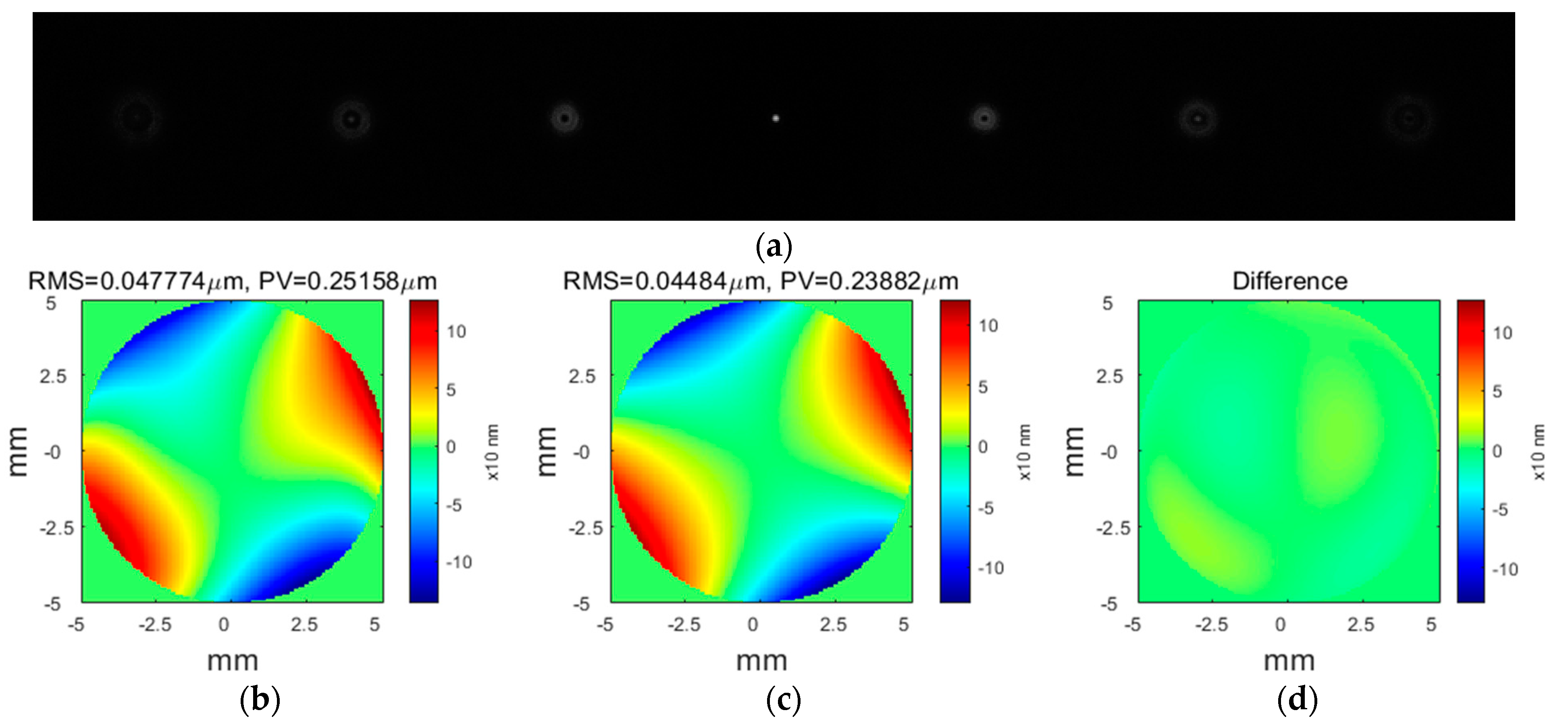
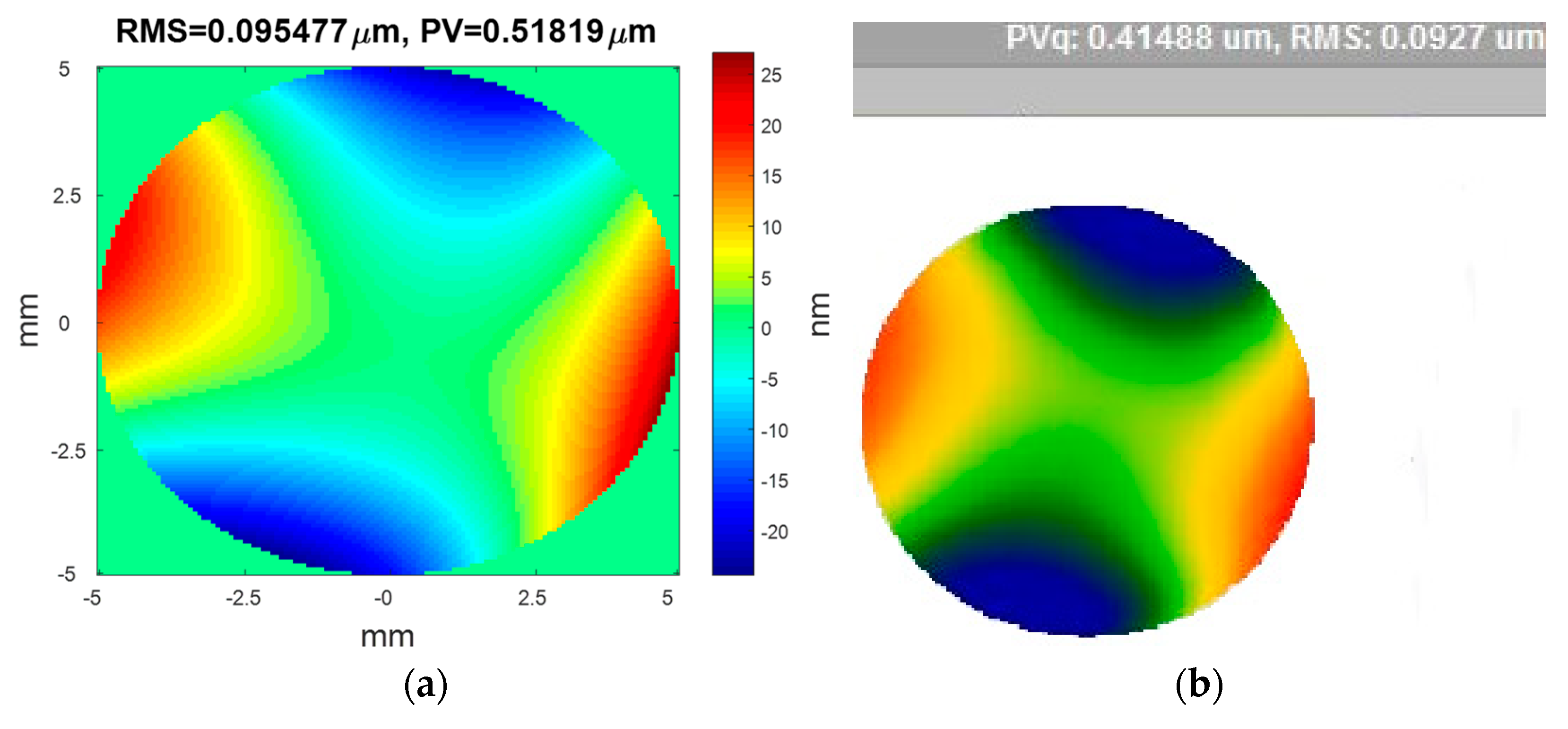
3. Experimental Demonstrations
4. Conclusions
Author Contributions
Funding
Data Availability Statement
Acknowledgments
Conflicts of Interest
References
- Ye, J.; Chen, L.; Li, X.; Yuan, Q.; Gao, Z. Review of optical freeform surface representation technique and its application. Opt. Eng. 2017, 56, 110901. [Google Scholar] [CrossRef]
- Wei, L.; Li, Y.; Jing, J.; Feng, L.; Zhou, J. Design and fabrication of a compact off-axis see-through head-mounted display using a freeform surface. Opt. Express 2018, 26, 8550–8565. [Google Scholar] [CrossRef] [PubMed]
- Wei, S.L.; Zhu, Z.B.; Fan, Z.C.; Yan, Y.M.; Ma, D.L. Multi-surface catadioptric freeform lens design for ultra-efficient off-axis road illumination. Opt. Express 2019, 27, A779–A789. [Google Scholar] [CrossRef]
- Meng, Q.; Wang, W.; Ma, H.; Dong, J. Easy-aligned off-axis three-mirror system with wide field of view using freeform surface based on integration of primary and tertiary mirror. Appl. Opt. 2014, 53, 3028–3034. [Google Scholar] [CrossRef] [PubMed] [Green Version]
- Wang, Q.; Cheng, D.; Wang, Y.; Hua, H.; Jin, G. Design, tolerance, and fabrication of an optical see-through head-mounted display with free-form surface elements. Appl. Opt. 2013, 52, C88–C99. [Google Scholar] [CrossRef] [PubMed]
- Zhu, R.H.; Sun, Y.; Shen, H. Progress and Prospect of Optical Freeform Surface Measurement. Acta Opt. Sin. 2021, 41, 0112001. [Google Scholar]
- Pant, K.K.; Burada, D.R.; Bichra, M.; Singh, M.P.; Ghosh, A.; Khan, G.S.; Sinzinger, S.; Shakher, C. Subaperture stitching for measurement of freeform wavefront. Appl. Opt. 2015, 54, 10022–10028. [Google Scholar] [CrossRef] [PubMed]
- El-Hayek, N.; Nouira, H.; Anwer, N.; Damak, M.; Gibaru, O. Reconstruction of freeform surfaces for metrology. J. Phys. Conf. Ser. 2014, 483, 012003. [Google Scholar] [CrossRef] [Green Version]
- DeFisher, S.; Bechtold, M.; Mohring, D. A non-contact surface measurement system for freeform and conformal optics. Proc. SPIE 2011, 8016, 80160W. [Google Scholar] [CrossRef]
- Ma, X.; Wang, J. Spherical mirror testing by phase retrieval wavefront sensor. Optik 2016, 127, 2396–2400. [Google Scholar] [CrossRef] [Green Version]
- Michalko, A.M.; Fienup, J.R. Sensitivity study of transverse translation diverse phase retrieval for freeform metrology. In Optical Manufacturing and Testing XII; International Society for Optics and Photonics: Bellingham, WA, USA, 2018; Volume 10742, p. 107420T. [Google Scholar]
- Moore, D.B.; Fienup, J. Subaperture translation estimation accuracy in transverse translation diversity phase retrieval. Appl. Opt. 2016, 55, 2526–2536. [Google Scholar] [CrossRef]
- Zeng, F.; Tan, Q.; Liu, Y.; Gu, H.; Zhou, Z.; Jin, G. Freeform metrology based on phase retrieval and computer-generated hologram. In Optical Design and Testing VI; International Society for Optics and Photonics: Bellingham, WA, USA, 2014; Volume 9272, p. 92720E. [Google Scholar]
- Fienup, J.; Marron, J.C.; Schulz, T.J.; Seldin, J.H. Hubble Space Telescope characterized by using phase-retrieval algorithms. Appl. Opt. 1993, 32, 1747–1767. [Google Scholar] [CrossRef] [PubMed] [Green Version]
- Dean, B.H.; Aronstein, D.L.; Smith, J.S.; Shiri, R.; Acton, D.S. Phase retrieval algorithm for JWST flight and testbed telescope. In Space Telescopes and Instrumentation I: Optical, Infrared, and Millimeter; International Society for Optics and Photonics: Bellingham, WA, USA, 2006; Volume 6265, p. 626511. [Google Scholar]
- Brady, G.R.; Guizar-Sicairos, M.; Fienup, J. Optical wavefront measurement using phase retrieval with transverse translation diversity. Opt. Express 2009, 17, 624–639. [Google Scholar] [CrossRef] [Green Version]
- Wu, Y.; Ding, L.; Hu, X. An improved phase retrieval algorithm for optical aspheric surface measurement. Opt. Commun. 2011, 284, 1496–1503. [Google Scholar] [CrossRef]
- Feng, Z.; Cheng, D.; Wang, Y. Transferring freeform lens design into phase retrieval through intermediate irradiance transport. Opt. Lett. 2019, 44, 5501–5504. [Google Scholar] [CrossRef]
- Michalko, A.M.; Fienup, J.R. Concave Mirror Measurement Using Transverse Translation Diverse Phase Retrieval. In Optical Fabrication and Testing; Optical Society of America: Washington, DC, USA, 2017; p. OW2B.5. [Google Scholar]
- Jurling, A.S.; Fienup, J.R. A numerical exploration of phase-retrieval error-metric surfaces. In Adaptive Optics System IV; International Society for Optics and Photonics: Bellingham, WA, USA, 2014; Volume 9148, p. 91486N. [Google Scholar]
- Moore, D.B.; Fienup, J.R. Extending the capture range of phase retrieval through random starting parameters. In Frontiers in Optics; OSA Technical Digest; Optical Society of America: Washington, DC, USA, 2014; p. FTu2C.2. [Google Scholar]
- Jurling, A.S.; Fienup, J.R. Applications of algorithmic differentiation to phase retrieval algorithms. J. Opt. Soc. Am. A 2014, 31, 1348–1359. [Google Scholar] [CrossRef]
- Lim, S.; Shin, J. Application of a Deep Neural Network to Phase Retrieval in Inverse Medium Scattering Problems. Computation 2021, 9, 56. [Google Scholar] [CrossRef]
- Ma, X.; Wang, J. The basic research of phase retrieval algorithm. Optik 2016, 127, 1561–1566. [Google Scholar] [CrossRef]
- Jurling, S.; Fienup, J.R. Phase retrieval with unknown sampling factors via the two-dimensional chirp-Z transform. J. Opt. Soc. Am. A 2014, 31, 1904–1911. [Google Scholar] [CrossRef] [Green Version]
- Tsai, Y.-J.; Bousse, A.; Ehrhardt, M.J.; Stearns, C.W.; Ahn, S.; Hutton, B.F.; Arridge, S.; Thielemans, K. Fast Quasi-Newton Algorithms for Penalized Reconstruction in Emission Tomography and Further Improvements via Preconditioning. IEEE Trans. Med. Imaging 2018, 37, 1000–1010. [Google Scholar] [CrossRef] [PubMed] [Green Version]
- Aşırım, Ö.E.; Yolalmaz, A.; Kuzuoğlu, M. High-Fidelity Harmonic Generation in Optical Micro-Resonators Using BFGS Algorithm. Micromachines 2020, 11, 686. [Google Scholar] [CrossRef] [PubMed]
Publisher’s Note: MDPI stays neutral with regard to jurisdictional claims in published maps and institutional affiliations. |
© 2022 by the authors. Licensee MDPI, Basel, Switzerland. This article is an open access article distributed under the terms and conditions of the Creative Commons Attribution (CC BY) license (https://creativecommons.org/licenses/by/4.0/).
Share and Cite
Ma, X.; Wang, J.; Wang, B.; Liu, X. Measurement of Small-Slope Free-Form Optical Surfaces with the Modified Phase Retrieval. Micromachines 2022, 13, 82. https://doi.org/10.3390/mi13010082
Ma X, Wang J, Wang B, Liu X. Measurement of Small-Slope Free-Form Optical Surfaces with the Modified Phase Retrieval. Micromachines. 2022; 13(1):82. https://doi.org/10.3390/mi13010082
Chicago/Turabian StyleMa, Xinxue, Jianli Wang, Bin Wang, and Xinyue Liu. 2022. "Measurement of Small-Slope Free-Form Optical Surfaces with the Modified Phase Retrieval" Micromachines 13, no. 1: 82. https://doi.org/10.3390/mi13010082
APA StyleMa, X., Wang, J., Wang, B., & Liu, X. (2022). Measurement of Small-Slope Free-Form Optical Surfaces with the Modified Phase Retrieval. Micromachines, 13(1), 82. https://doi.org/10.3390/mi13010082