
Dual-Frequency Polarized Reconfigurable Terahertz Antenna Based on Graphene Metasurface and TOPAS


Abstract
:1. Introduction
2. Materials and Design
2.1. Graphene Material
2.2. TOPAS Material
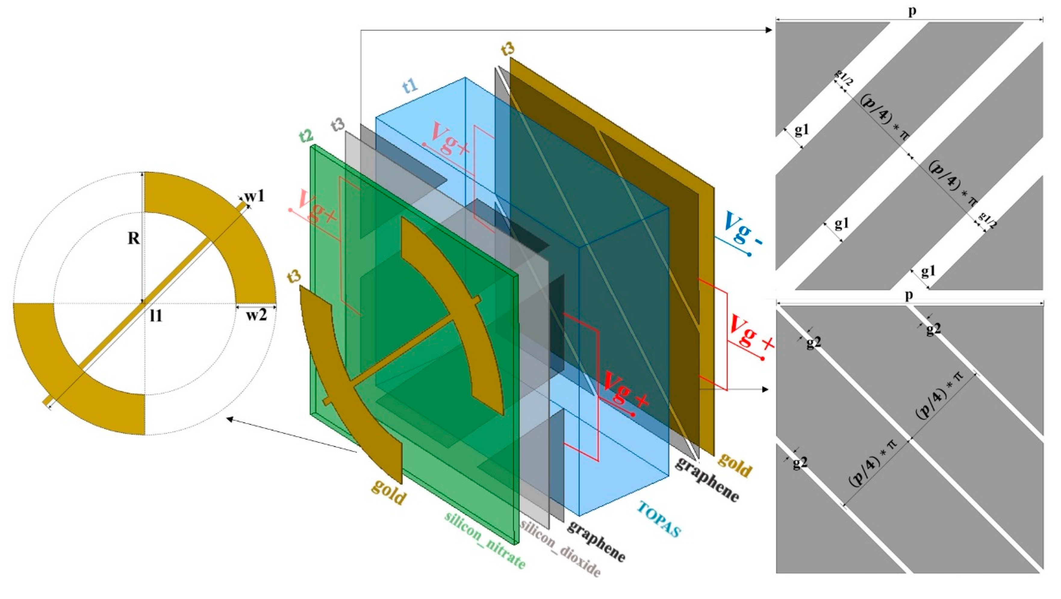
2.3. PCM Unit
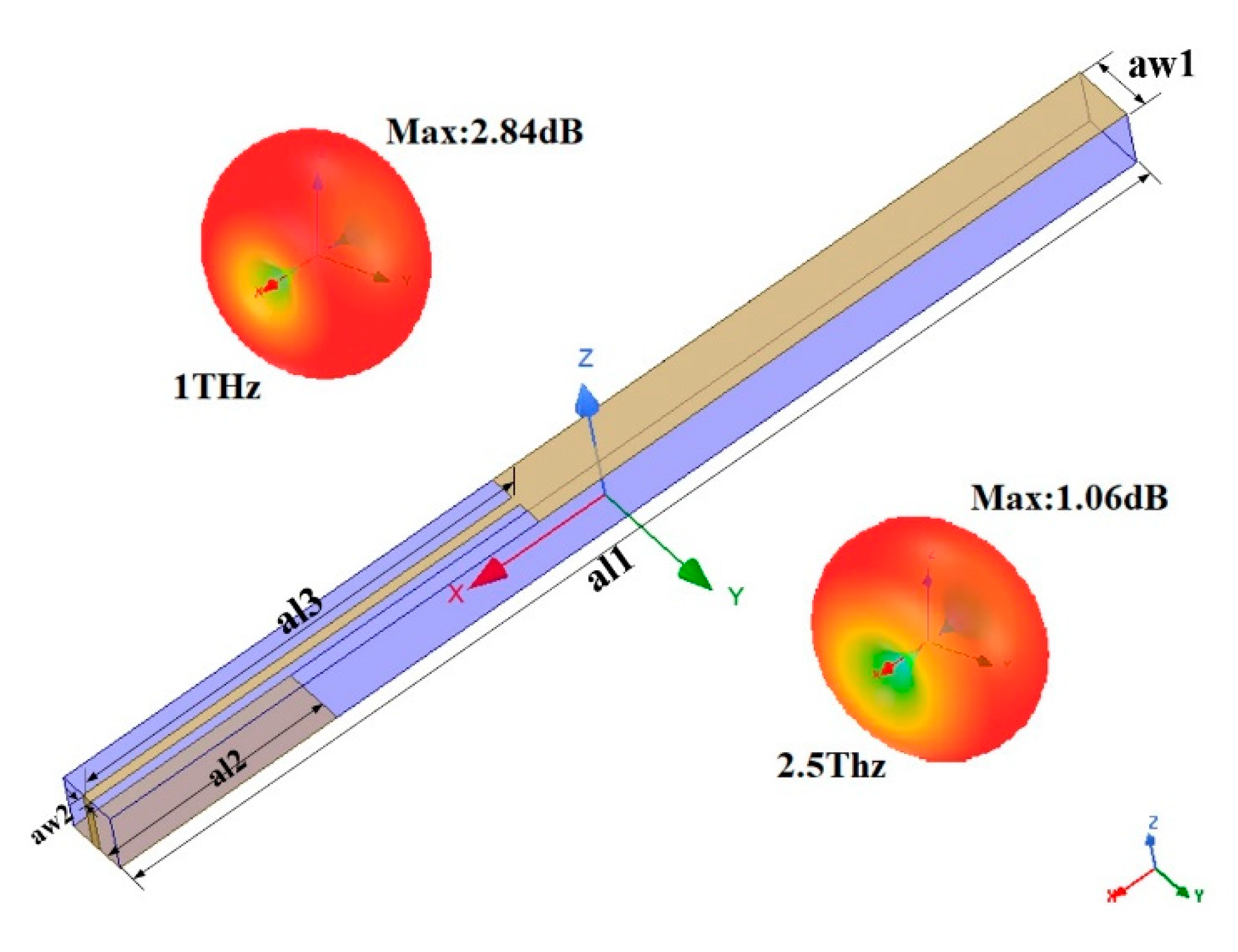
2.4. Dual-Band THz Antenna
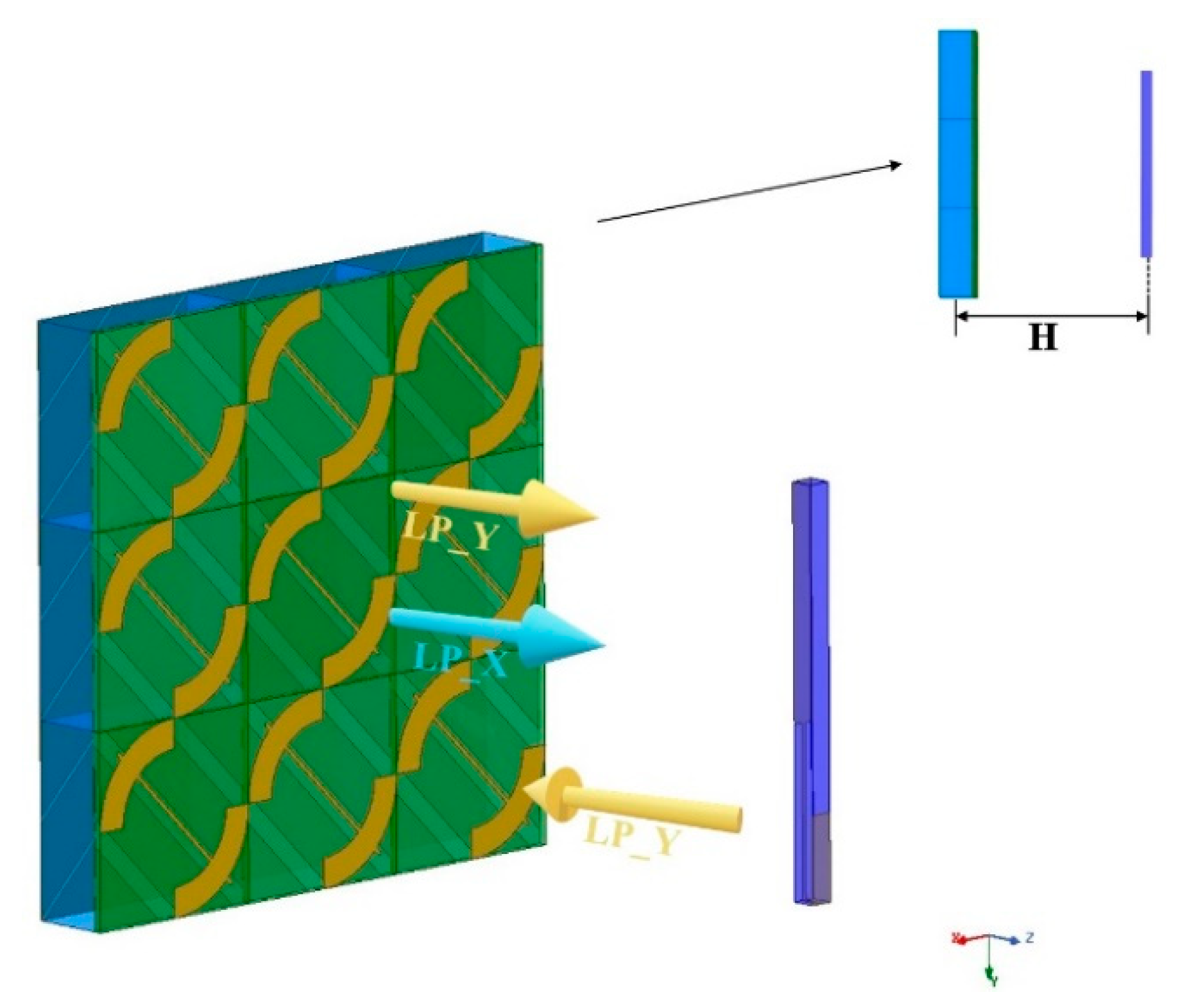
2.5. Antenna-PCM Hybrid Structure
2.6. Simulation Setup
3. Results and Discussions
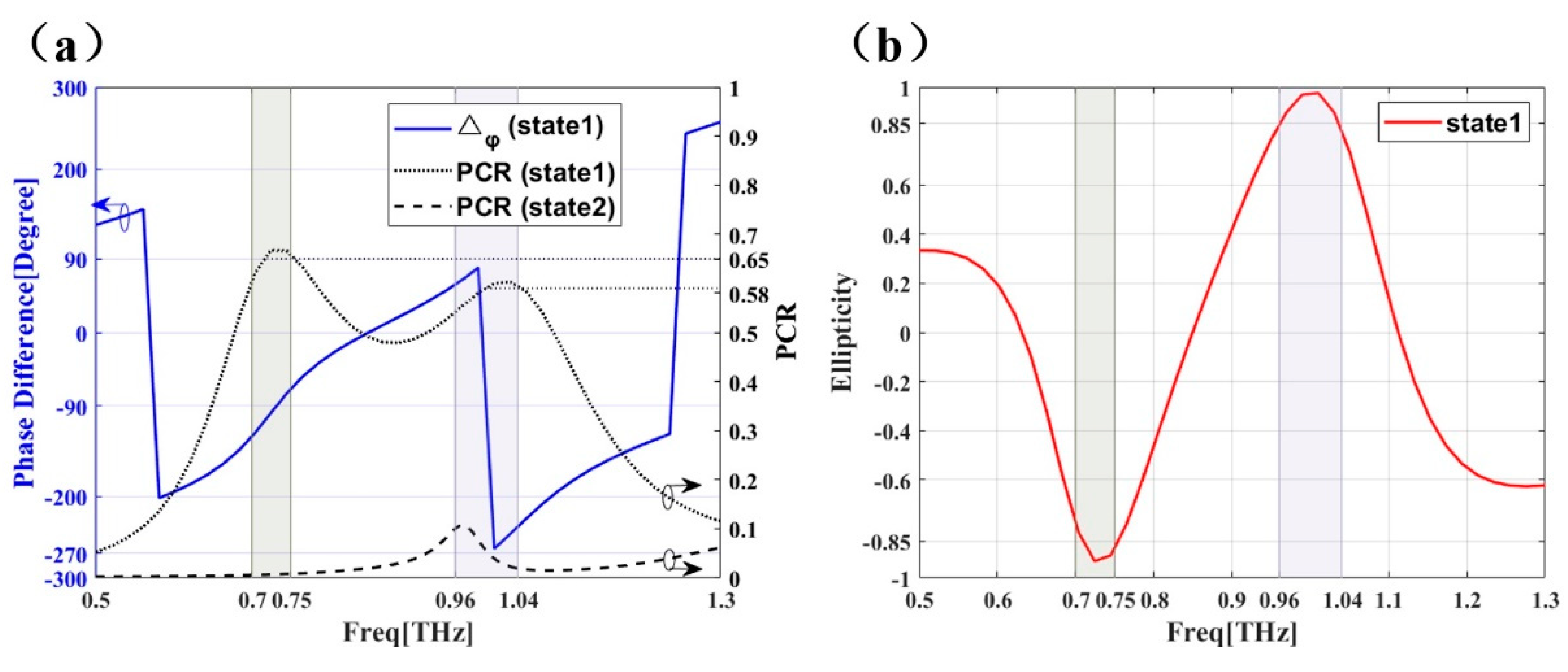
3.1. PCM Unit’s Performance
3.2. Dual-Band THz Antenna’s Performance
3.3. Performance of the Antenna-PCM Hybrid Structure
4. Conclusions
Author Contributions
Funding
Institutional Review Board Statement
Informed Consent Statement
Data Availability Statement
Conflicts of Interest
References
- Hiromoto, N.; Fukasawa, R.; Hosako, I. Measurement of optical properties of construction materials in the terahertz region. In Proceedings of the International Conference on Infrared and Millimeter Waves, Shanghai, China, 18–22 September 2006; p. 157. [Google Scholar]
- Zhang, H.; Li, Z.; Hu, F.; Chen, T.; Qin, B.; Zhao, Y. Sensitive detection of chlorpheniramine maleate using THz combined with metamaterials. Opt. Quantum Electron. 2017, 49, 258. [Google Scholar] [CrossRef]
- Lajunen, H.; Turunen, J.; Tervo, J. Design of polarization gratings for broadband illumination. Opt. Express 2005, 13, 3055–3067. [Google Scholar] [CrossRef]
- Li, W.; Xia, S.; He, B.; Chen, J.; Shi, H.; Zhang, A.; Li, Z.; Xu, Z. A reconfigurable polarization converter using active metasurface and its application in horn antenna. IEEE Trans. Antennas Propag. 2016, 64, 5281–5290. [Google Scholar] [CrossRef]
- Zhu, H.L.; Cheung, S.W.; Liu, X.H.; Yuk, T.I. Design of polarization reconfigurable antenna using metasurface. IEEE Trans. Antennas Propag. 2014, 62, 2891–2898. [Google Scholar] [CrossRef]
- Sharma, V.K.; Madaan, D.; Kapoor, A. Extremely short length and high extinction ratio plasmonic TE mode pass polarizer. IEEE Photonics Technol. Lett. 2017, 29, 559–562. [Google Scholar] [CrossRef]
- Wu, J.L.; Yuan, X.G.; Zhang, Y.G.; Yan, X.; Zhang, X. Dual-tunable broadband terahertz absorber based on a hybrid graphene-dirac semimetal structure. Micromachines 2020, 11, 1096. [Google Scholar] [CrossRef] [PubMed]
- Qu, M.; Chang, T.; Guo, G.; Li, S. Design of graphene-based dual-polarized switchable rasorber/absorber at terahertz. IEEE Access 2020, 8, 127220–127225. [Google Scholar] [CrossRef]
- Kim, D. Performance uniformity analysis of a wire-grid polarizer in imaging polarimetry. Appl. Opt. 2005, 44, 5398–5402. [Google Scholar] [CrossRef] [Green Version]
- Saurav, K.; Sarkar, D.; Srivastava, K.V. CRLH unit-cell loaded multiband printed dipole antenna. IEEE Antennas Wirel. Propag. Lett. 2014, 13, 852–855. [Google Scholar] [CrossRef]
- Cong, L.; Xu, N.; Gu, J.; Singh, R.; Han, J.; Zhang, W. Highly flexible broadband terahertz metamaterial quarter-wave plate. Laser Photonics Rev. 2014, 8, 626–632. [Google Scholar] [CrossRef]
- Grady, N.K.; Heyes, J.E.; Chowdhury, D.R.; Zeng, Y.; Reiten, M.T.; Azad, A.K.; Taylor, A.J.; Dalvit, D.A.R.; Chen, H.-T. Terahertz metamaterials for linear polarization conversion and anomalous refraction. Science 2013, 340, 1304–1307. [Google Scholar] [CrossRef] [PubMed] [Green Version]
- Wu, L.; Yang, Z.; Cheng, Y.; Gong, R.; Zhao, M.; Zheng, Y.; Duan, J.; Yuan, X. Circular polarization converters based on bi-layered asymmetrical split ring metamaterials. Appl. Phys. A Mater. Sci. Process. 2014, 116, 643–648. [Google Scholar] [CrossRef]
- Zheludev, N.I. Obtaining optical properties on demand. Science 2015, 348, 973–974. [Google Scholar] [CrossRef] [PubMed] [Green Version]
- Zhang, H.-F.; Zeng, L.; Liu, G.-B.; Huang, T. Tunable linear-to-circular polarization converter using the graphene transmissive metasurface. IEEE Access 2019, 7, 158634–158642. [Google Scholar] [CrossRef]
- Novoselov, K.S.; Geim, A.K.; Morozov, S.V.; Jiang, D.; Zhang, Y.; Dubonos, S.V.; Grigorieva, I.V.; Firsov, A.A. Electric field effect in atomically thin carbon films. Science 2004, 306, 666–669. [Google Scholar] [CrossRef] [PubMed] [Green Version]
- Hanson, G.W. Dyadic Green's functions for an anisotropic, non-local model of biased graphene. IEEE Trans. Antennas Propag. 2008, 56, 747–757. [Google Scholar] [CrossRef]
- Fang, Z.; Wang, Y.; Liu, Z.; Schlather, A.; Ajayan, P.M.; Koppens, F.H.L.; Nordlander, P.; Halas, N.J. Plasmon-induced doping of graphene. ACS Nano 2012, 6, 10222–10228. [Google Scholar] [CrossRef] [PubMed]
- Luo, S.; Li, B.; Yu, A.; Gao, J.; Wang, X.; Zuo, D. Broadband tunable terahertz polarization converter based on graphene metamaterial. Opt. Commun. 2018, 413, 184–189. [Google Scholar] [CrossRef]
- Yadav, V.S.; Ghosh, S.K.; Bhattacharyya, S.; Das, S. Graphene-based metasurface fora unable broadband terahertz cross-polarization converter over a wide angle of incidence. Appl. Opt. 2018, 57, 8720–8726. [Google Scholar] [CrossRef]
- Ren, Q.; You, J.W.; Panoiu, N.-C. Comparison between the linear and nonlinear homogenization of graphene and silicon metasurfaces. IEEE Access 2020, 8, 175753–175764. [Google Scholar] [CrossRef]
- Yu, X.; Gao, X.; Qiao, W.; Wen, L.; Yang, W. Broadband tunable polarization converter realized by graphene-based metamaterial. IEEE Photonics Technol. Lett. 2016, 28, 2399–2402. [Google Scholar] [CrossRef]
- Quader, S.; Zhang, J.; Akram, M.R.; Zhu, W. Graphene-based high-efficiency broadband tunable linear-to-circular polarization converter for terahertz waves. IEEE J. Sel. Top. Quantum Electron. 2020, 26, 1–8. [Google Scholar] [CrossRef]
- Zeng, L.; Huang, T.; Liu, G.-B.; Zhang, H.-F. A tunable ultra-broadband linear-to-circular polarization converter containing the graphene. Opt. Commun. 2019, 436, 7–13. [Google Scholar] [CrossRef]
- Danciu, M.; Alexa-Stratulat, T.; Stefanescu, C.; Dodi, G.; Tamba, B.I.; Mihai, C.T.; Stanciu, G.D.; Luca, A.; Spiridon, I.A.; Ungureanu, L.B.; et al. Terahertz spectroscopy and imaging: A cutting-edge method for diagnosing digestive cancers. Materials 2019, 12, 1519. [Google Scholar] [CrossRef] [PubMed] [Green Version]
- Son, J.-H.; Oh, S.J.; Cheon, H. Potential clinical applications of terahertz radiation. J. Appl. Phys. 2019, 125, 190901. [Google Scholar] [CrossRef]
- Lee, D.-K.; Kim, G.; Kim, C.; Jhon, Y.M.; Kim, J.H.; Lee, T.; Son, J.-H.; Seo, M. Ultrasensitive detection of residual pesticides using THz near-field enhancement. IEEE Trans. Terahertz Sci. Technol. 2016, 6, 389–395. [Google Scholar] [CrossRef]
- Filter, R.; Farhat, M.; Steglich, M.; Alaee, R.; Rockstuhl, C.; Lederer, F. Tunable graphene antennas for selective enhancement of THz-emission. Opt. Express 2013, 21, 3737–3745. [Google Scholar] [CrossRef] [Green Version]
- Wu, B.; Hu, Y.; Zhao, Y.T.; Lu, W.B.; Zhang, W. Large angle beam steering THz antenna using active frequency selective surface based on hybrid graphene-gold structure. Opt. Express 2018, 26, 15353–15361. [Google Scholar] [CrossRef]
- Zhu, H.L.; Cheung, S.W.; Chung, K.L.; Yuk, T.I. Linear-to-circular polarization conversion using metasurface. IEEE Trans. Antennas Propag. 2013, 61, 4615–4623. [Google Scholar] [CrossRef] [Green Version]
- Nielsen, K.; Rasmussen, H.K.; Adam, A.J.L.; Planken, P.C.M.; Bang, O.; Jepsen, P.U. Bendable, low-loss Topas fibers for the terahertz frequency range. Opt. Express 2009, 17, 8592–8601. [Google Scholar] [CrossRef] [Green Version]
- Hanson, G.W. Dyadic Green’s functions and guided surface waves for a surface conductivity model of graphene. J. Appl. Phys. 2008, 103, 64302. [Google Scholar] [CrossRef] [Green Version]
- Gómez-Díaz, J.S.; Perruisseau-Carrier, J. Graphene-based plasmonic switches at near infrared frequencies. Opt. Express 2013, 21, 15490–15504. [Google Scholar] [CrossRef] [Green Version]
- Kaminsky, W.; Arndt, M. Metallocenes for polymer catalysis. In Polymer Synthesis/Polymer Catalysis; Springer: Berlin/Heidelberg, Germany, 1997; Volume 127, pp. 143–187. [Google Scholar]
- Khanarian, G.; Celanese, H. Optical properties of cyclic olefin copolymers. Opt. Eng. 2001, 40, 1024–1029. [Google Scholar] [CrossRef]
- Cunningham, P.D.; Valdes, N.N.; Vallejo, F.A.; Hayden, L.M.; Polishak, B.; Zhou, X.H.; Luo, J.D.; Jen, A.K.Y.; Williams, J.C.; Twieg, R.J. Broadband terahertz characterization of the refractive index and absorption of some important polymeric and organic electro-optic materials. J. Appl. Phys. 2011, 109, 43505. [Google Scholar] [CrossRef] [Green Version]
- Liu, W.W.; Song, Z.Y. Terahertz absorption modulator with largely tunable bandwidth and intensity. Carbon 2021, 174, 617–624. [Google Scholar] [CrossRef]
- Zhang, Y.; Feng, Y.J.; Zhao, J.M. Graphene-enabled tunable multifunctional metamaterial for dynamical polarization manipulation of broadband terahertz wave. Carbon 2020, 163, 244–252. [Google Scholar] [CrossRef]
- Li, X.; Cai, W.; An, J.; Kim, S.; Nah, J.; Yang, D.; Piner, R.; Velamakanni, A.; Jung, I.; Tutuc, E.; et al. Large-area synthesis of high-quality and uniform graphene films on copper foils. Science 2009, 324, 1312–1314. [Google Scholar] [CrossRef] [PubMed] [Green Version]
- Lin, I.T.; Liu, J.M.; Shi, K.Y.; Tseng, P.S.; Wu, K.H.; Luo, C.W.; Li, L.J. Terahertz optical properties of multilayer graphene: Experimental observation of strong dependence on stacking arrangements and misorientation angles. Phys. Rev. B 2012, 86, 235446. [Google Scholar] [CrossRef]
- Huang, C.; Yang, J.N.; Ji, C.; Yuan, L.M.; Luo, X.G. Graphene-driven metadevice for active microwave camouflage with high-efficiency transmission window. Small Methods 2021, 5, 2000918. [Google Scholar] [CrossRef]
- Kruskopf, M.; Pakdehi, D.M.; Pierz, K.; Wundrack, S.; Stosch, R.; Dziomba, T.; Goetz, M.; Baringhaus, J.; Aprojanz, J.; Tegenkamp, C.; et al. Comeback of epitaxial graphene for electronics: Large-area growth of bilayer-free graphene on SiC. 2D Mater. 2016, 3, 41002. [Google Scholar] [CrossRef]
- Stankovich, S.; Dikin, D.A.; Piner, R.D.; Kohlhaas, K.A.; Kleinhammes, A.; Jia, Y.; Wu, Y.; Nguyen, S.T.; Ruoff, R.S. Synthesis of graphene-based nanosheets via chemical reduction of exfoliated graphite oxide. Carbon 2007, 45, 1558–1565. [Google Scholar] [CrossRef]
- Tour, J.M. Top-down versus bottom-up fabrication of graphene-based electronics. Chem. Mater. 2014, 26, 163–171. [Google Scholar] [CrossRef]
- Seniutinas, G.; Gervinskas, G.; Balcytis, A.; Clark, F.; Nishijima, Y.; Krotkus, A.; Molis, G.; Valusis, G.; Juodkazis, S. Nanoscale precision in ion milling for optical and terahertz antennas. In Proceedings of the Conference on Advanced Fabrication Technologies for Micro/Nano Optics and Photonics VIII, San Francisco, CA, USA, 8–11 February 2015. [Google Scholar]
- Wei, Z.; Cao, Y.; Fan, Y.; Yu, X.; Li, H. Broadband polarization transformation via enhanced asymmetric transmission through arrays of twisted complementary split-ring resonators. Appl. Phys. Lett. 2011, 99. [Google Scholar] [CrossRef] [Green Version]
- Shi, H.; Li, J.; Zhang, A.; Wang, J.; Xu, Z. Broadband cross polarization converter using plasmon hybridizations in a ring/disk cavity. Opt. Express 2014, 22, 20973–20981. [Google Scholar] [CrossRef]
- Feng, M.; Wang, J.; Ma, H.; Mo, W.; Ye, H.; Qu, S. Broadband polarization rotator based on multi-order plasmon resonances and high impedance surfaces. J. Appl. Phys. 2013, 114. [Google Scholar] [CrossRef] [Green Version]
- Fu, C.F.; Sun, Z.J.; Han, L.F.; Liu, C.; Sun, T.; Chu, P.K. High-efficiency dual-frequency reflective linear polarization converter based on metasurface for microwave bands. Appl. Sci. 2019, 9, 1910. [Google Scholar] [CrossRef] [Green Version]
- Nakamura, T.; Fukusako, T. Broadband design of circularly polarized microstrip patch antenna using artificial ground structure with rectangular unit cells. IEEE Trans. Antennas Propag. 2011, 59, 2103–2110. [Google Scholar] [CrossRef]
- Lv, X.-L.; Wu, B.; Zhao, Y.-T.; Zu, H.-R.; Lu, W.-B. Dual-band dual-polarization reconfigurable THz antenna based on graphene. Appl. Phys. Express 2020, 13, 75007. [Google Scholar] [CrossRef]
- Mei, Z.L.; Ma, X.M.; Lu, C.; Zhao, Y.D. High-efficiency and wide-bandwidth linear polarization converter based on double U-shaped metasurface. AIP Adv. 2017, 7, 125323. [Google Scholar] [CrossRef] [Green Version]
- Sajjad, M.; Kong, X.K.; Liu, S.B.; Ahmed, A.; Rahman, S.U.; Wang, Q. Graphene-based THz tunable ultra-wideband polarization converter. Phys. Lett. A 2020, 384, 126567. [Google Scholar] [CrossRef]
- Akram, M.R.; Mehmood, M.Q.; Bai, X.D.; Jin, R.H.; Premaratne, M.; Zhu, W.R. High efficiency ultrathin transmissive metasurfaces. Adv. Opt. Mater. 2019, 7, 1801628. [Google Scholar] [CrossRef]
- Rahman, S.U.; Cao, Q.S.; Akram, M.R.; Amin, F.; Wang, Y. Multifunctional polarization converting metasurface and its application to reduce the radar cross-section of an isolated MIMO antenna. J. Phys. D Appl. Phys. 2020, 53, 305001. [Google Scholar] [CrossRef]


| Parameter | Length (um) | Parameter | Length (um) |
|---|---|---|---|
| t1 | 18.5 | w2 | 15 |
| t2 | 2 | R | 49 |
| t3 | 0.1 | p | 49 |
| w1 | 1 | g1 | 5 |
| l1 | 53 | g2 | 1 |
| Parameter | Length (um) |
|---|---|
| aw1 | 6 |
| aw2 | 1 |
| al1 | 103 |
| al2 | 22 |
| al3 | 44 |
| Reference | Tunability | Bandwidth | Centre or Resonance Frequency | Hybrid Structure |
|---|---|---|---|---|
| [49] | No | 3.98 GHz (9.38–13.36 GHz) | 11.4 GHz | No |
| 5.52 GHz (14.84–20.36 GHz) | 17.6 GHz | |||
| [50] | No | 5.52 GHz (14.84–20.36 GHz) | 5.97 GHz | Yes |
| 1.23 GHz (5.40–6.63 GHz) | 6.02 GHz | |||
| [29] | Yes | 180 GHz (1.38–1.56 THz) | 1.44 THz | Yes |
| [51] | Yes | 28 GHz (1.302–1.33 THz) | 1.32 THz | Yes |
| 80 GHz (1.46–1.54 THz) | 1.51 THz | |||
| This paper | Yes | 260 GHz (0.76–1.02 THz) | 1.0 THz | Yes |
| 170 GHz (2.43–2.67 THz) | 2.5 THz |
Publisher’s Note: MDPI stays neutral with regard to jurisdictional claims in published maps and institutional affiliations. |
© 2021 by the authors. Licensee MDPI, Basel, Switzerland. This article is an open access article distributed under the terms and conditions of the Creative Commons Attribution (CC BY) license (https://creativecommons.org/licenses/by/4.0/).
Share and Cite
Zhang, J.; Tao, S.; Yan, X.; Zhang, X.; Guo, J.; Wen, Z. Dual-Frequency Polarized Reconfigurable Terahertz Antenna Based on Graphene Metasurface and TOPAS. Micromachines 2021, 12, 1088. https://doi.org/10.3390/mi12091088
Zhang J, Tao S, Yan X, Zhang X, Guo J, Wen Z. Dual-Frequency Polarized Reconfigurable Terahertz Antenna Based on Graphene Metasurface and TOPAS. Micromachines. 2021; 12(9):1088. https://doi.org/10.3390/mi12091088
Chicago/Turabian StyleZhang, Jinnan, Shijie Tao, Xin Yan, Xia Zhang, Jinxuan Guo, and Zhiqiang Wen. 2021. "Dual-Frequency Polarized Reconfigurable Terahertz Antenna Based on Graphene Metasurface and TOPAS" Micromachines 12, no. 9: 1088. https://doi.org/10.3390/mi12091088
APA StyleZhang, J., Tao, S., Yan, X., Zhang, X., Guo, J., & Wen, Z. (2021). Dual-Frequency Polarized Reconfigurable Terahertz Antenna Based on Graphene Metasurface and TOPAS. Micromachines, 12(9), 1088. https://doi.org/10.3390/mi12091088