
Enhancing the Shock Response Performance of Micromachined Silicon Resonant Accelerometers by Electrostatic Active Damping Control

 and
and
Abstract
:1. Introduction
2. Shock Response Analysis
3. Micromachined Silicon Resonant Accelerometer Based on Electrostatic Active Damping Control
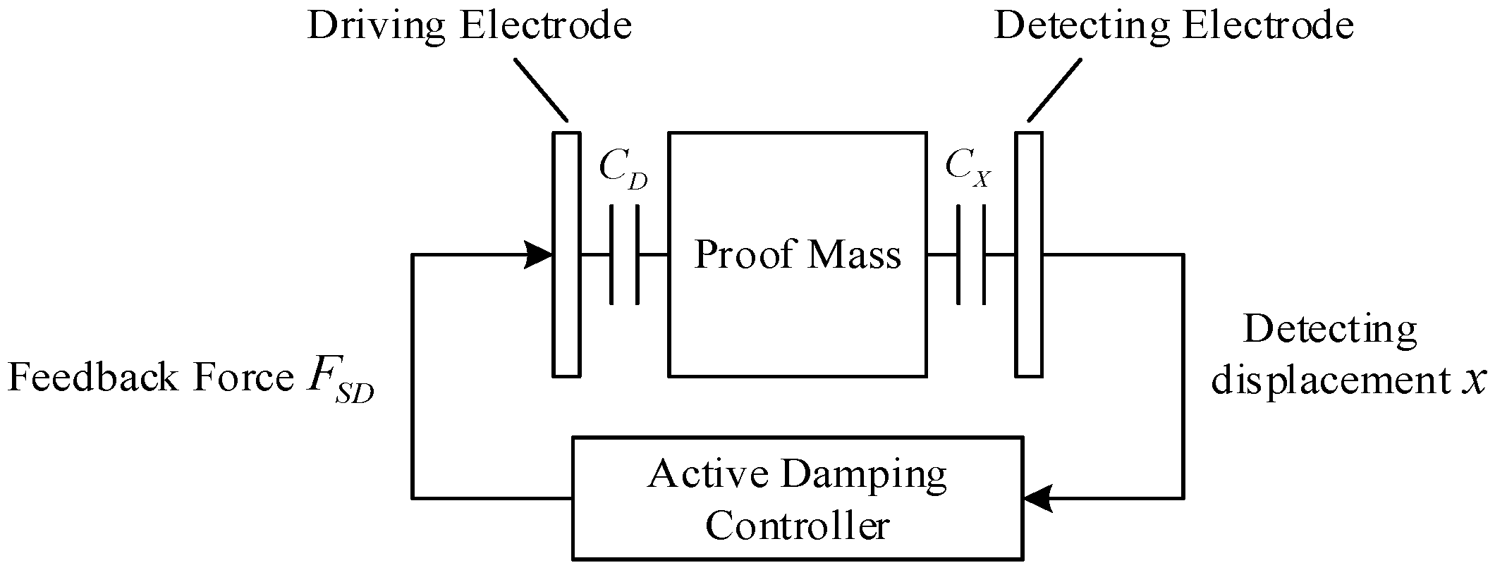
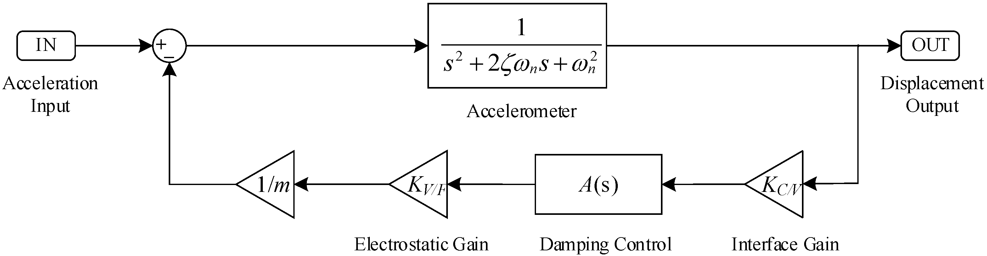
3.1. Basic Principles of Electrostatic Active Damping Control
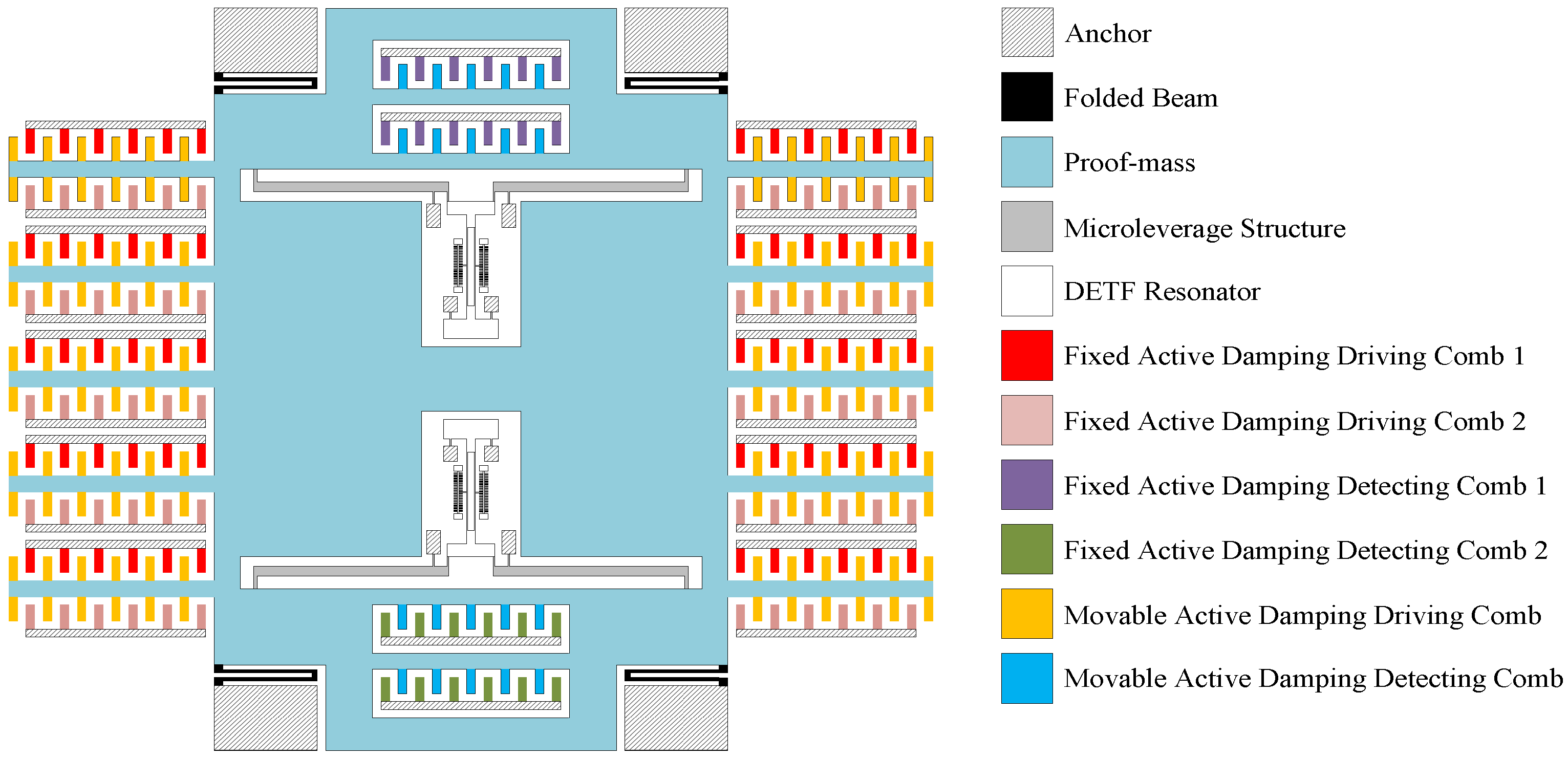
3.2. Structural Design
3.3. Damping Control Circuit
3.3.1. Calculation of System Parameters
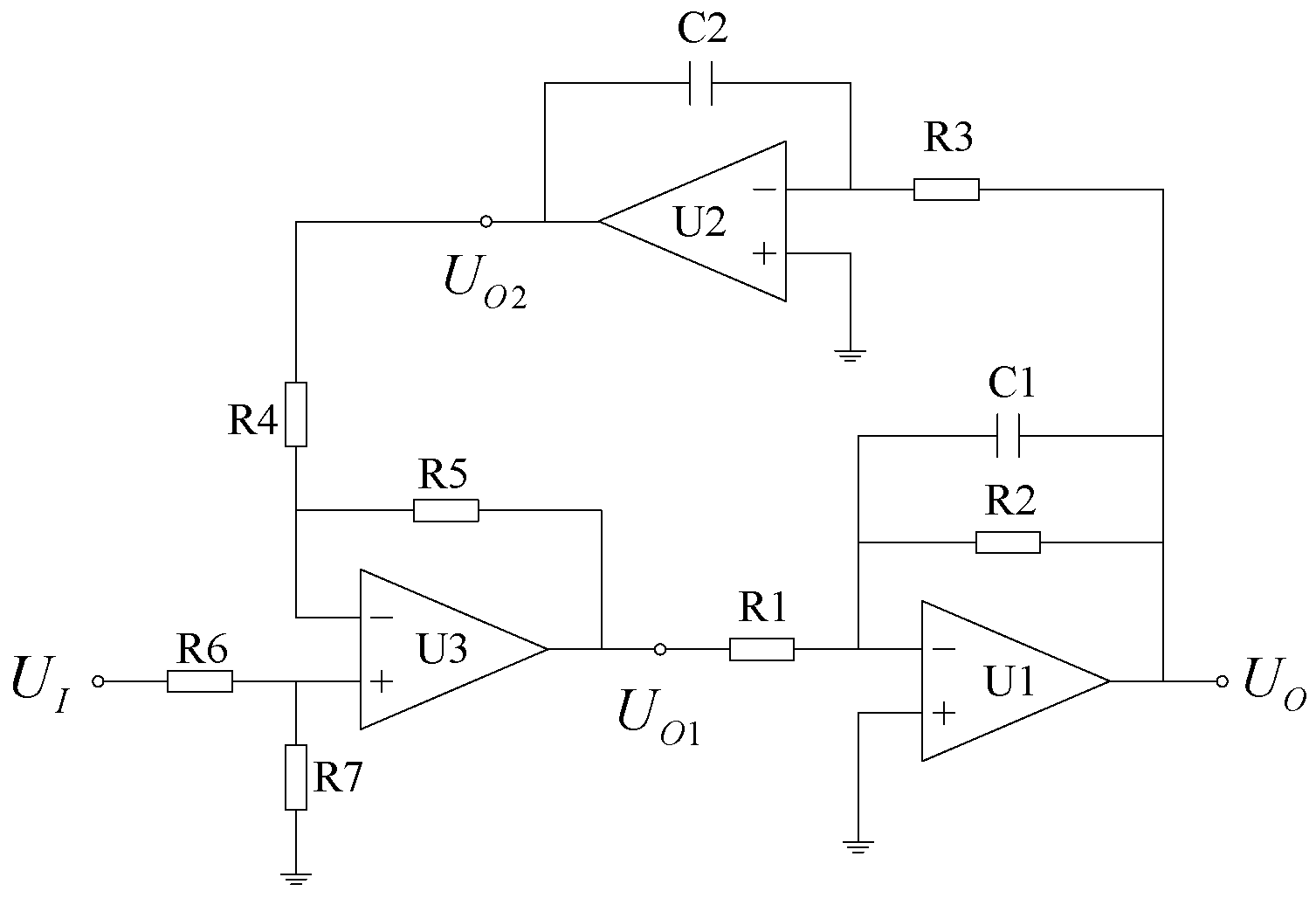
3.3.2. Damping Control Circuit Design
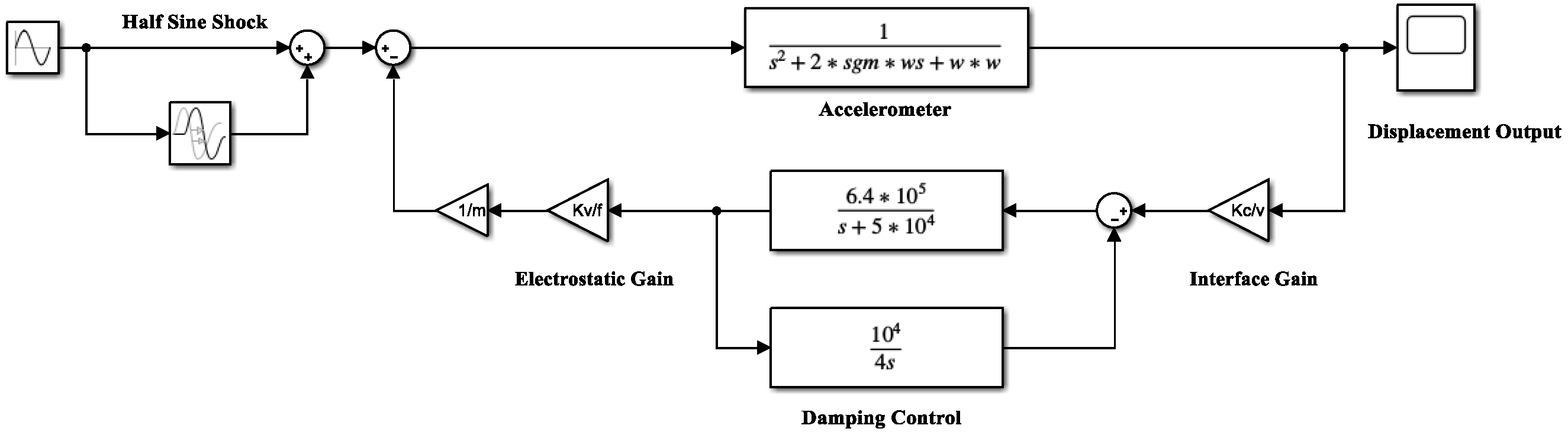
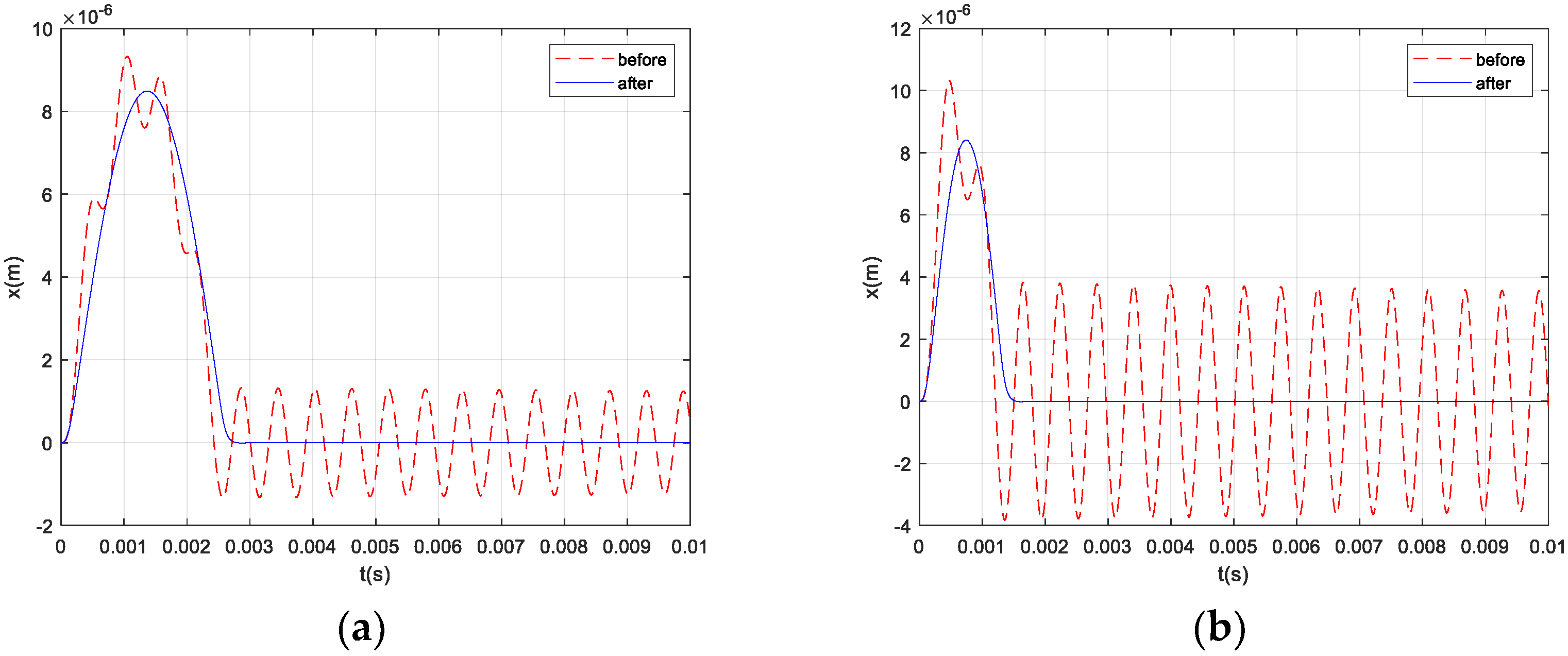
3.3.3. System Simulation and Analysis
4. Experiments
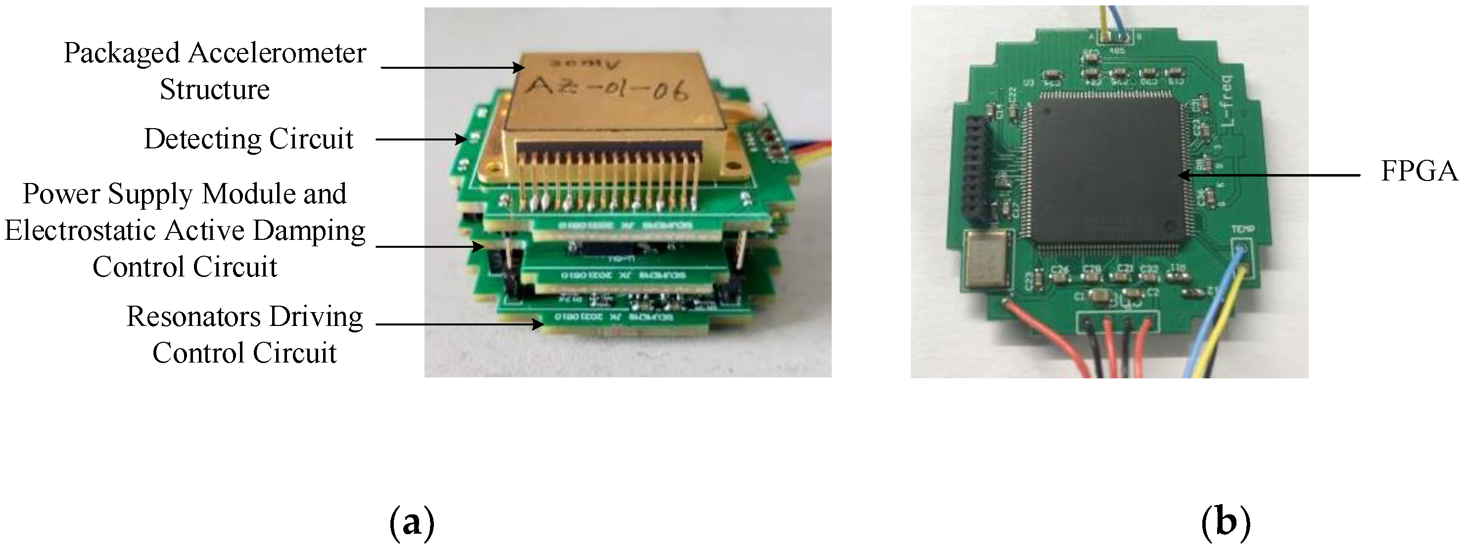
4.1. Fabricated Accelerometer Structure
4.2. Test Circuit and Equipment
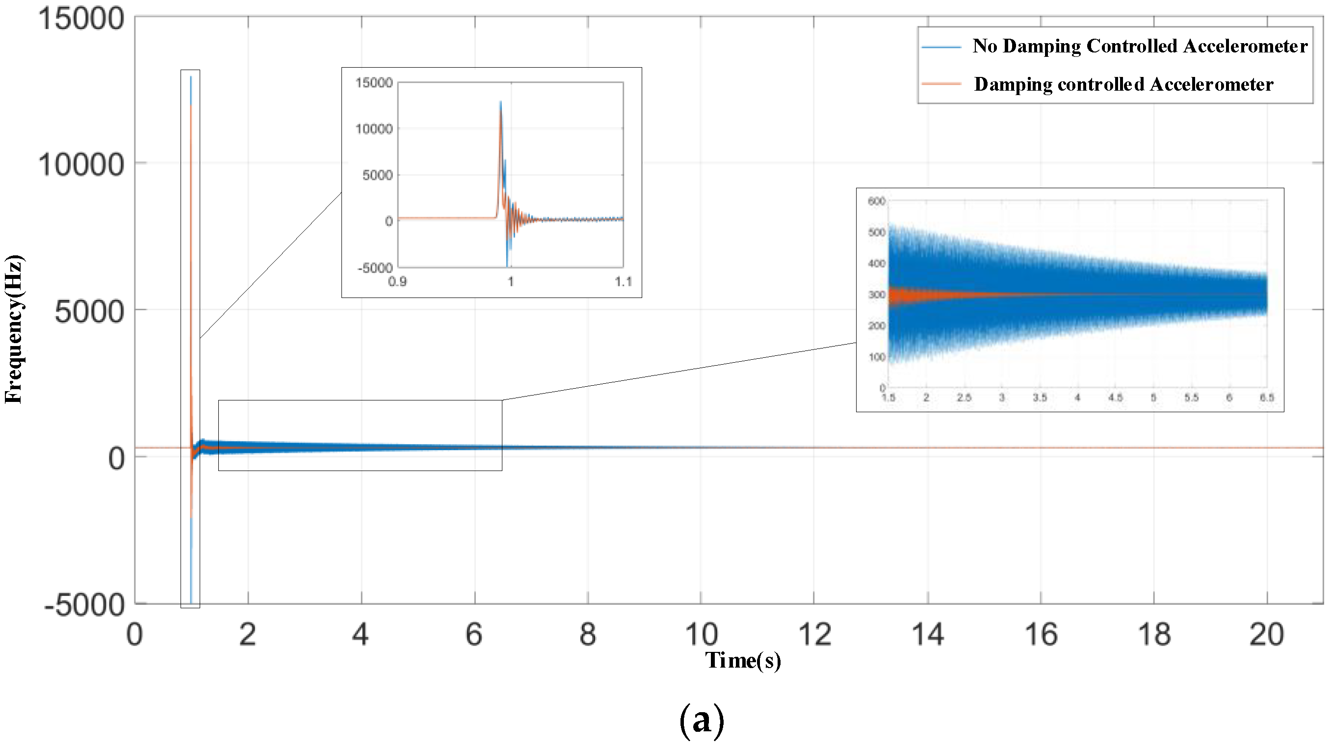
4.3. Shock Experiments
5. Discussion
6. Conclusions
Author Contributions
Funding
Conflicts of Interest
References
- Yin, Y.G.; Fang, Z.X.; Han, F.T.; Yan, B.; Dong, J.X.; Wu, Q.P. Design and test of a micromachined resonant accelerometer with high scale factor and low noise. Sens. Actuators A Phys. 2017, 268, 52–60. [Google Scholar] [CrossRef]
- Fain, B.; Souchon, F.; Berthelot, A.; Anciant, R.; Robert, P.; Jourdan, G. Suppression of the resonance of vacuum-sealed accelerometers: A comparison of two different strategies. In Proceedings of the 2018 5th IEEE International Symposium on Inertial Sensors and Systems (INERTIAL), Lake Como, Italy, 26–29 March 2018; pp. 1–4. [Google Scholar]
- Liu, Y.F.; Liu, J.L.; Ma, G.Y. Design and Analysis of Close-Loop Control System of Electrostatic Force-Balance Quartz-Flexure Accelerometer. Aerosp. Control Appl. 2019, 45, 67–71, 78. [Google Scholar]
- Lavinia, C.; Olivier, B.; Helene, T.; Jerome, E.; Thierry, C. 3-axis high Q MEMS accelerometer with simultaneous damping control. In Proceedings of the 2016 14th IEEE International New Circuits and Systems Conference (NEWCAS), Vancouver, BC, Canada, 26–29 July 2016; pp. 1–4. [Google Scholar]
- Yang, Z.X.; Huang, Y.; Li, X.X.; Chen, G.N. Investigation and simulation on the dynamic shock response performance of packaged high-g MEMS accelerometer versus the impurity concentration of the piezoresistor. Microelectron. Reliab. 2009, 49, 510–516. [Google Scholar] [CrossRef]
- Meyer, Y.; Collet, M. Active vibration isolation of electronic components by piezocomposite clamped-clamped beam. Mech. Syst. Signal Process. 2011, 25, 1687–1701. [Google Scholar] [CrossRef] [Green Version]
- Dienel, M.; Naumann, M.; Sorger, A.; Tenholte, D.; Voigt, S.; Mehner, J. On the influence of vacuum on the design and characterization of MEMS. Vacuum 2012, 86, 536–546. [Google Scholar] [CrossRef]
- Kavitha, C.; Madhan, M.G. Study of squeeze film damping characteristics under different gas mediums in a capacitive MEMS accelerometer. J. Braz. Soc. Mech. Sci. Eng. 2016, 38, 241–252. [Google Scholar] [CrossRef]
- Zhang, Y.; Pan, W. Packaging Technology for MEMS. Nanotechnol. Precis. Eng. 2005, 3, 194–198. [Google Scholar]
- Srikar, V.T.; Senturia, S.D. The reliability of microelectromechanical systems (MEMS) in shock environments. J. Microelectromech. Syst. 2002, 11, 206–214. [Google Scholar] [CrossRef]
- Tudor, M.J.; Andres, M.V.; Foulds, K.W.H.; Naden, J.M. Silicon resonator sensors: Interrogation techniques and characteristics. IEE Proc. Part D 1988, 135, 364–368. [Google Scholar] [CrossRef]
- Valoff, S.; Kaiser, W.J. Presettable micromachined MEMS accelerometers. In Proceedings of the Technical Digest, IEEE International MEMS 99 Conference, Twelfth IEEE International Conference on Micro Electro Mechanical Systems (Cat. No.99CH36291), Orlando, FL, USA, 21 January 1999; pp. 72–76. [Google Scholar]
- Zheng, R.H.; Ren, S.Y.; Chen, G.P.; Chen, H.H. Multi-shaker half sine shock on random mixed vibration control. J. Sound Vib. 2021, 512, 116372. [Google Scholar] [CrossRef]
- Ciotirca, L.E.; Bernal, O.; Enjalbert, J.; Cassagnes, T.; Tap, H.; Beaulaton, H.; Sahin, S. New Stability Method of a Multirate Controller for a Three-Axis High-Q MEMS Accelerometer With Simultaneous Electrostatic Damping. IEEE Sens. J. 2018, 18, 6106–6114. [Google Scholar] [CrossRef] [Green Version]
- Ahmed, M.S.; Ghommem, M.; Abdelkefi, A. Shock response of electrostatically coupled microbeams under the squeeze-film damping effect. Acta Mech. 2018, 229, 5051–5065. [Google Scholar] [CrossRef]
- Huang, L.; Yang, H.; Gao, Y.; Zhao, L.; Liang, J. Design and Implementation of a Micromechanical Silicon Resonant Accelerometer. Sensors 2013, 13, 15785–15804. [Google Scholar] [CrossRef] [PubMed]
- Harrison, D.R.; Dimeff, J. A Diode-Quad Bridge Circuit for Use with Capacitance Transducers. Rev. Sci. Instrum. 1973, 44, 1468–1472. [Google Scholar] [CrossRef]
- Guo, G.F.; Wu, S.X.; Cao, D. Transient Responses of Second-order System. Appl. Mech. Mater. 2011, 55–57, 224–228. [Google Scholar] [CrossRef]


| Parameters | Values |
|---|---|
| Proof mass equivalent area (m2) | 22.89 × 10⁻⁶ |
| Structure thickness (μm) | 60 |
| Number of active damping driving combs | 6480 |
| Active damping driving comb gap (μm) | 4 |
| Active damping driving comb length (μm) | 30 |
| Initial overlap length of active damping driving combs (μm) | 15 |
| Active damping driving comb width (μm) | 4 |
| Number of active damping detecting combs | 1200 |
| Active damping detecting comb gap (μm) | 4 |
| Active damping detecting comb length (μm) | 30 |
| Initial overlap length of active damping detecting combs (μm) | 15 |
| Active damping detecting comb width (μm) | 4 |
| Spacing between silicon structure and glass base (μm) | 20 |
| Simulation Parameters | Values |
|---|---|
| Damping ratio | 8.1833 × 10⁻⁴ |
| Undamped free vibration angular frequency (rad/s) | 10,681 |
| Front-end interface gain | 1.376 × 10⁶ |
| Damping control circuit gain | 4 × 10⁻⁴ |
| Damping control circuit turning frequency (kHz) | 6.4 |
| Damping control circuit equivalent damping ratio | 0.6 |
| DC drive voltage (V) | 60 |
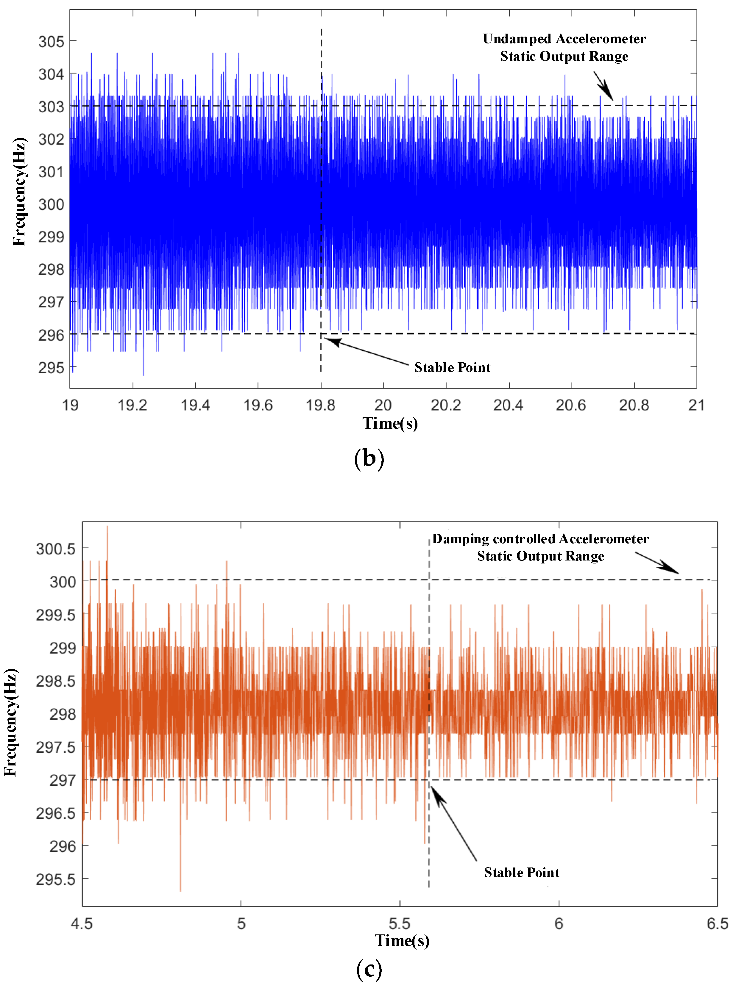
| Index | No Damping Control | Damping Control |
|---|---|---|
| Stabilization time (s) | 19.8 | 5.6 |
| Average value of frequency difference before shock (Hz) | 299.88205 | 298.1226832 |
| Average value of frequency difference after stabilization (Hz) | 300.00029 | 298.0979416 |
Publisher’s Note: MDPI stays neutral with regard to jurisdictional claims in published maps and institutional affiliations. |
© 2021 by the authors. Licensee MDPI, Basel, Switzerland. This article is an open access article distributed under the terms and conditions of the Creative Commons Attribution (CC BY) license (https://creativecommons.org/licenses/by/4.0/).
Share and Cite
Huang, L.; Jiang, K.; Wang, P.; Zhang, M.; Ding, X.; Li, H. Enhancing the Shock Response Performance of Micromachined Silicon Resonant Accelerometers by Electrostatic Active Damping Control. Micromachines 2021, 12, 1548. https://doi.org/10.3390/mi12121548
Huang L, Jiang K, Wang P, Zhang M, Ding X, Li H. Enhancing the Shock Response Performance of Micromachined Silicon Resonant Accelerometers by Electrostatic Active Damping Control. Micromachines. 2021; 12(12):1548. https://doi.org/10.3390/mi12121548
Chicago/Turabian StyleHuang, Libin, Kai Jiang, Peng Wang, Meimei Zhang, Xukai Ding, and Hongsheng Li. 2021. "Enhancing the Shock Response Performance of Micromachined Silicon Resonant Accelerometers by Electrostatic Active Damping Control" Micromachines 12, no. 12: 1548. https://doi.org/10.3390/mi12121548
APA StyleHuang, L., Jiang, K., Wang, P., Zhang, M., Ding, X., & Li, H. (2021). Enhancing the Shock Response Performance of Micromachined Silicon Resonant Accelerometers by Electrostatic Active Damping Control. Micromachines, 12(12), 1548. https://doi.org/10.3390/mi12121548