
Theoretical Thermal-Mechanical Modelling and Experimental Validation of a Three-Dimensional (3D) Electrothermal Microgripper with Three Fingers


Abstract
:1. Introduction
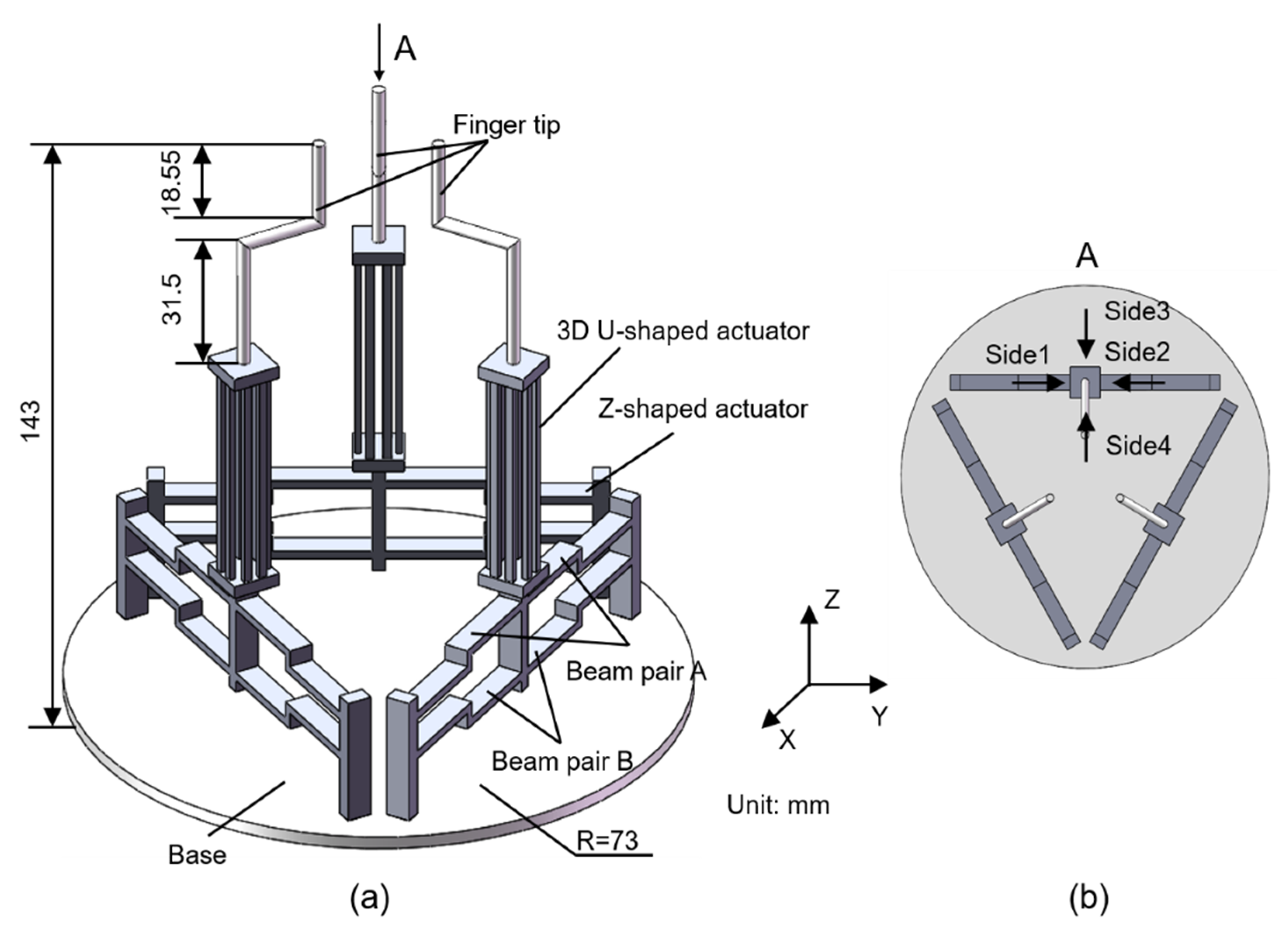
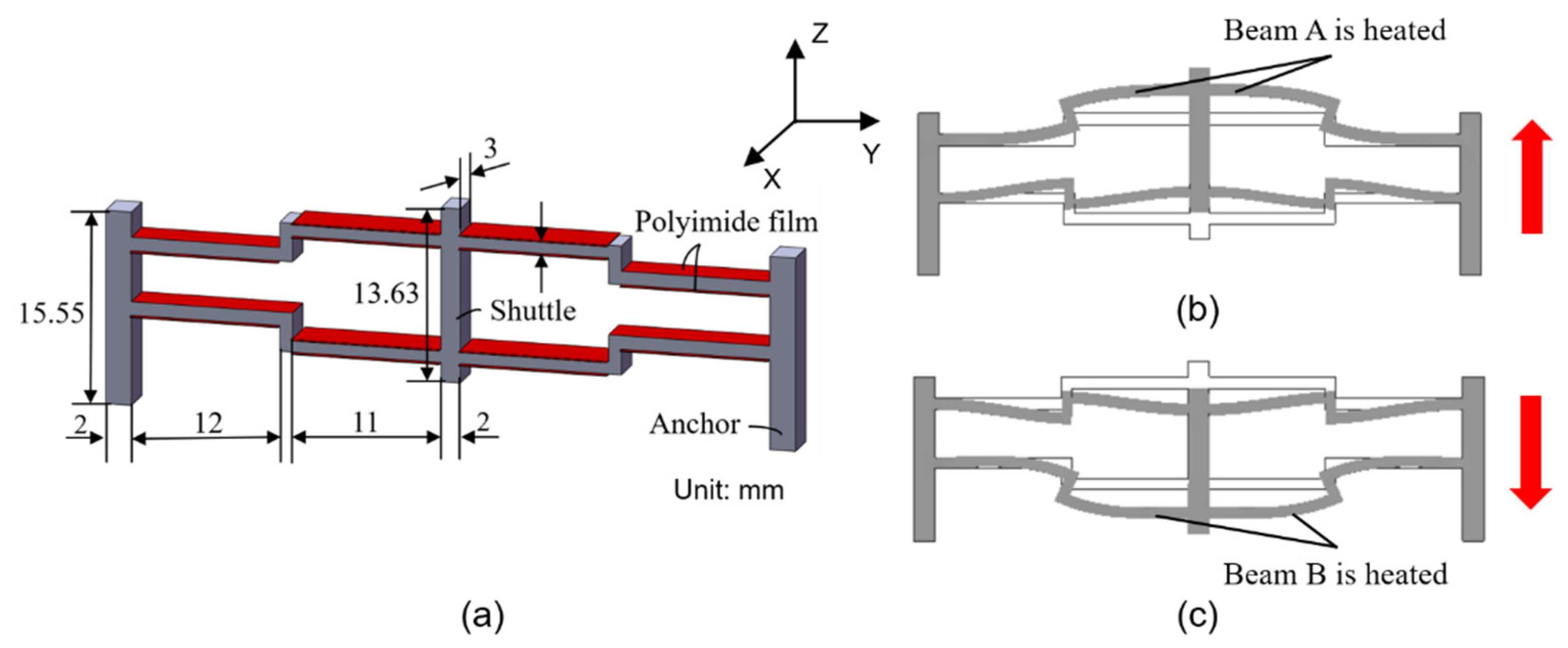
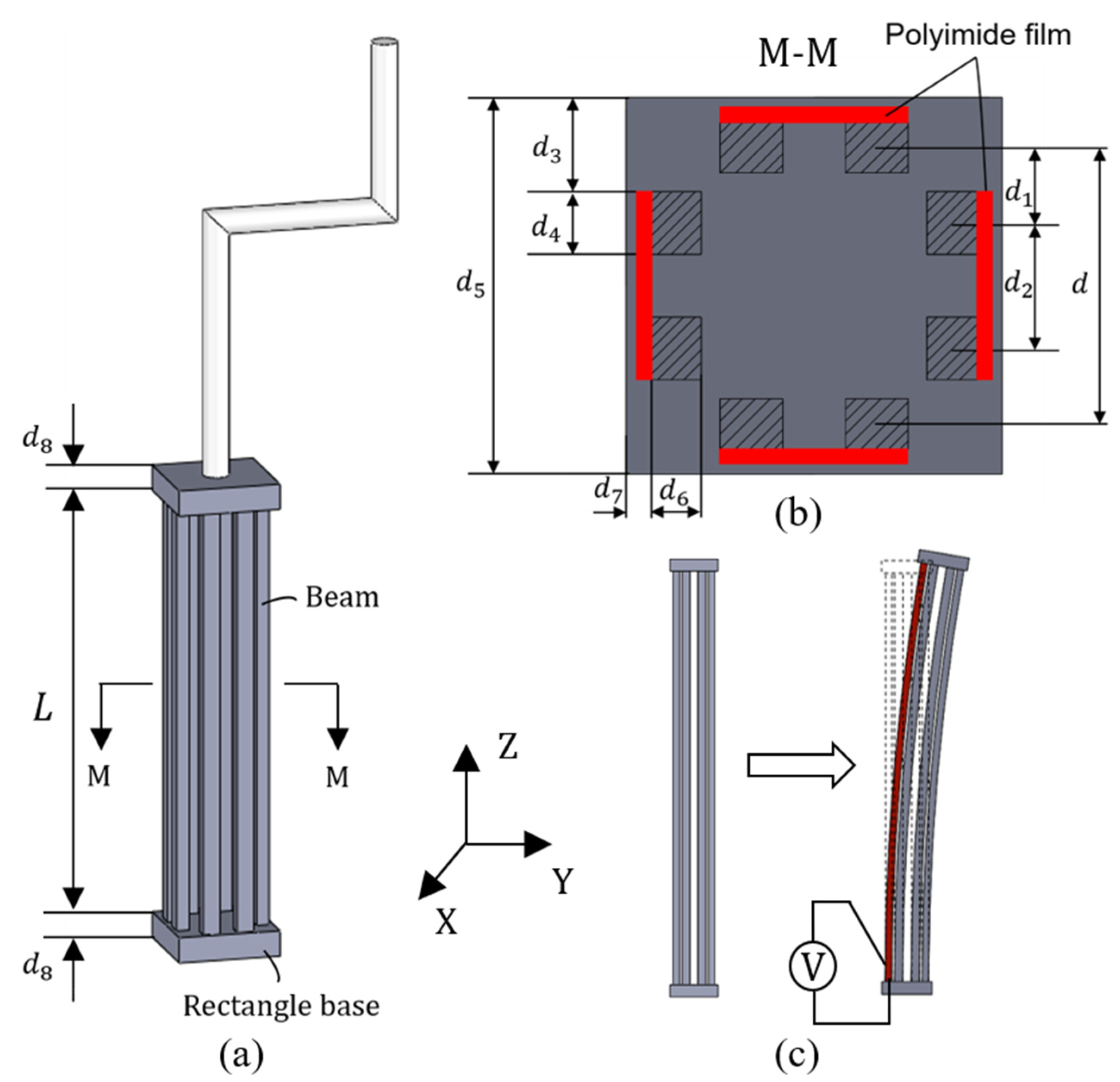
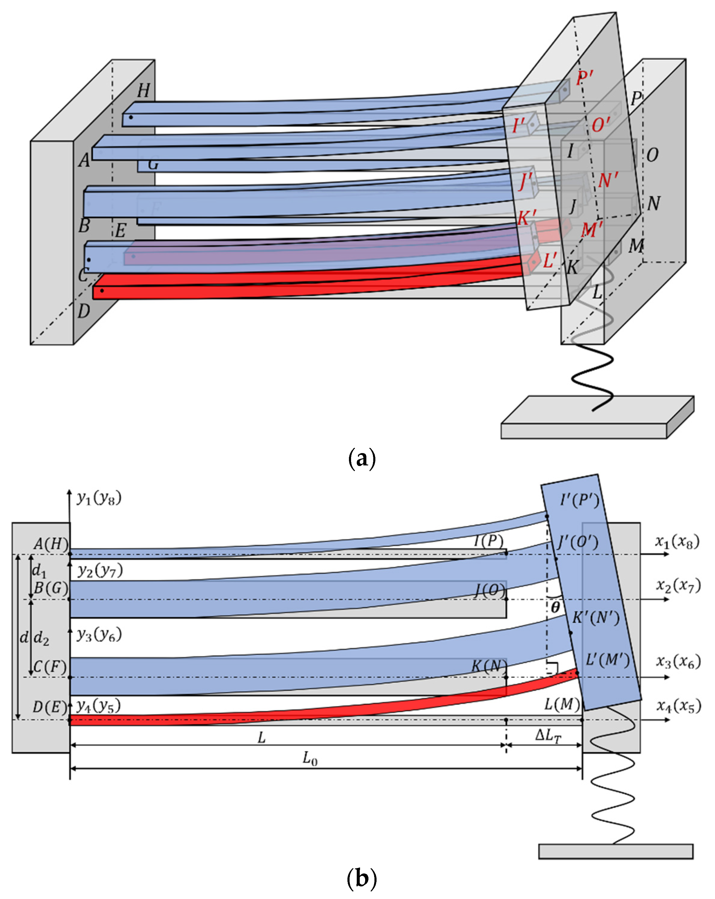
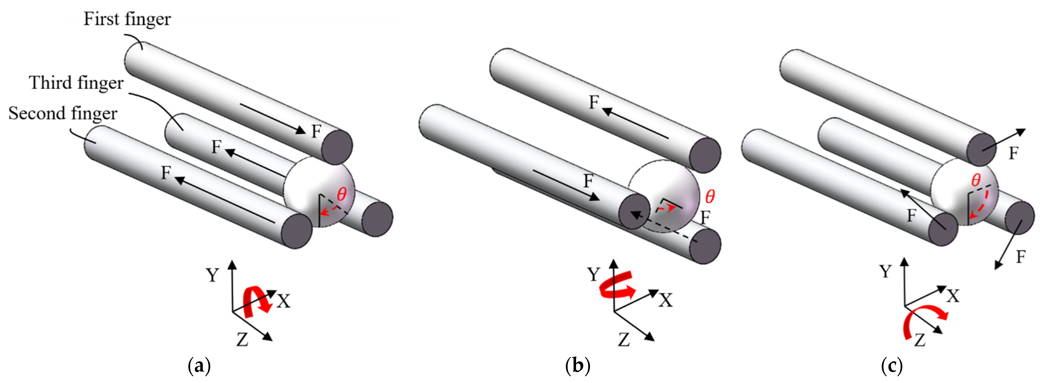
2. Structural Design of the 3D U-Shaped Electrothermal Actuator
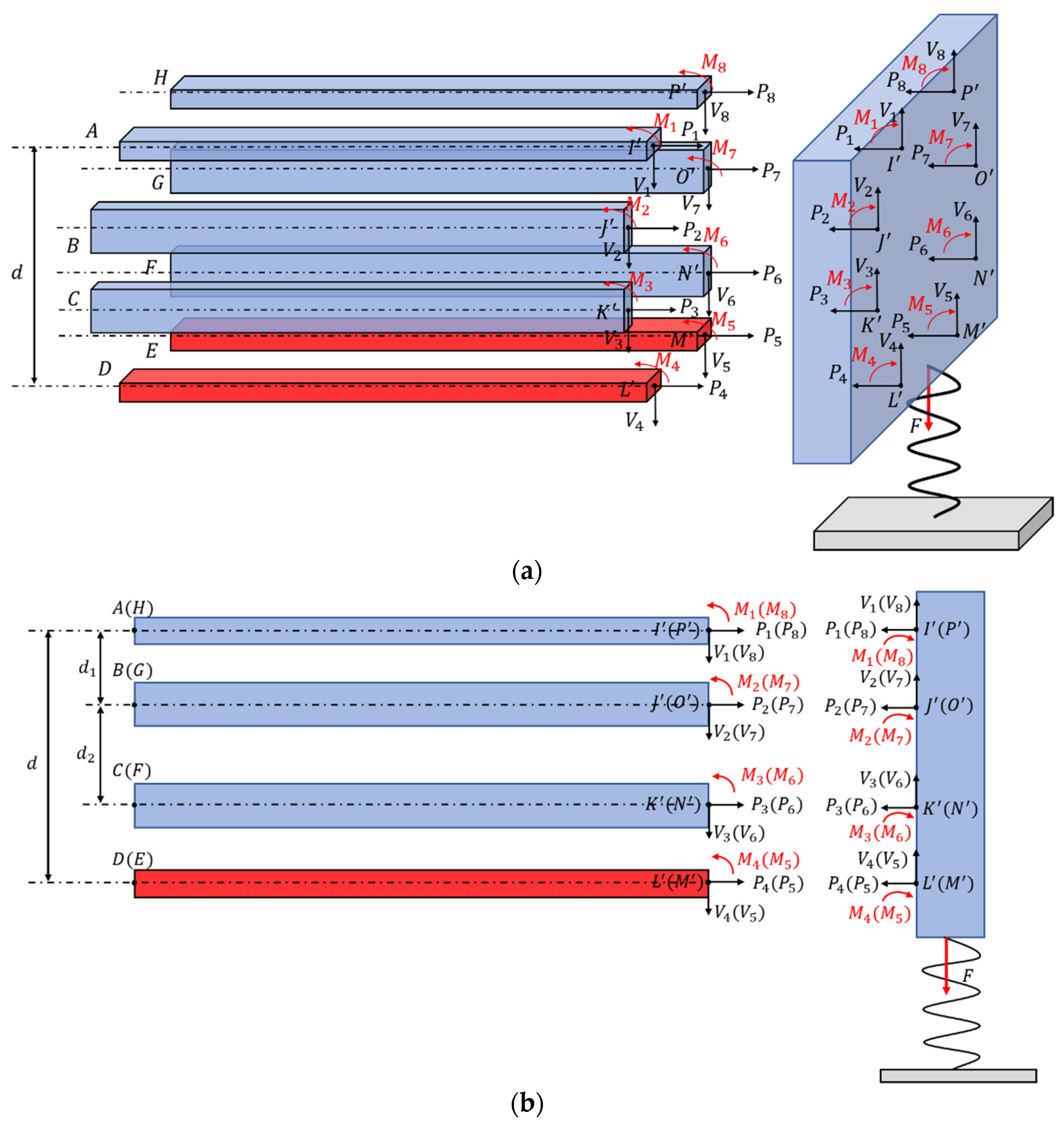
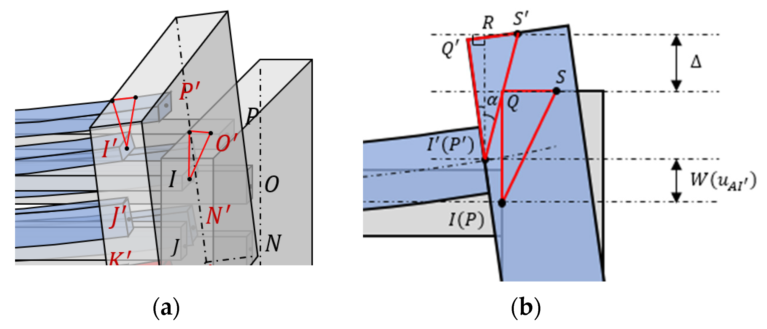
3. Theoretical Modeling of the 3D U-Shaped Actuator
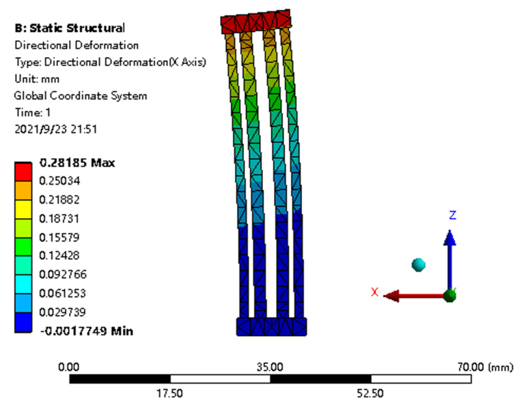
4. Finite Element Analysis of the 3D U-Shaped Actuator
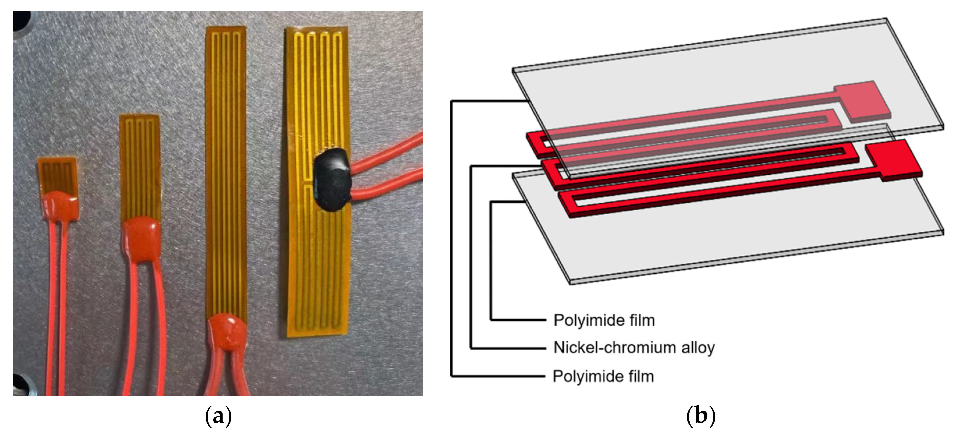
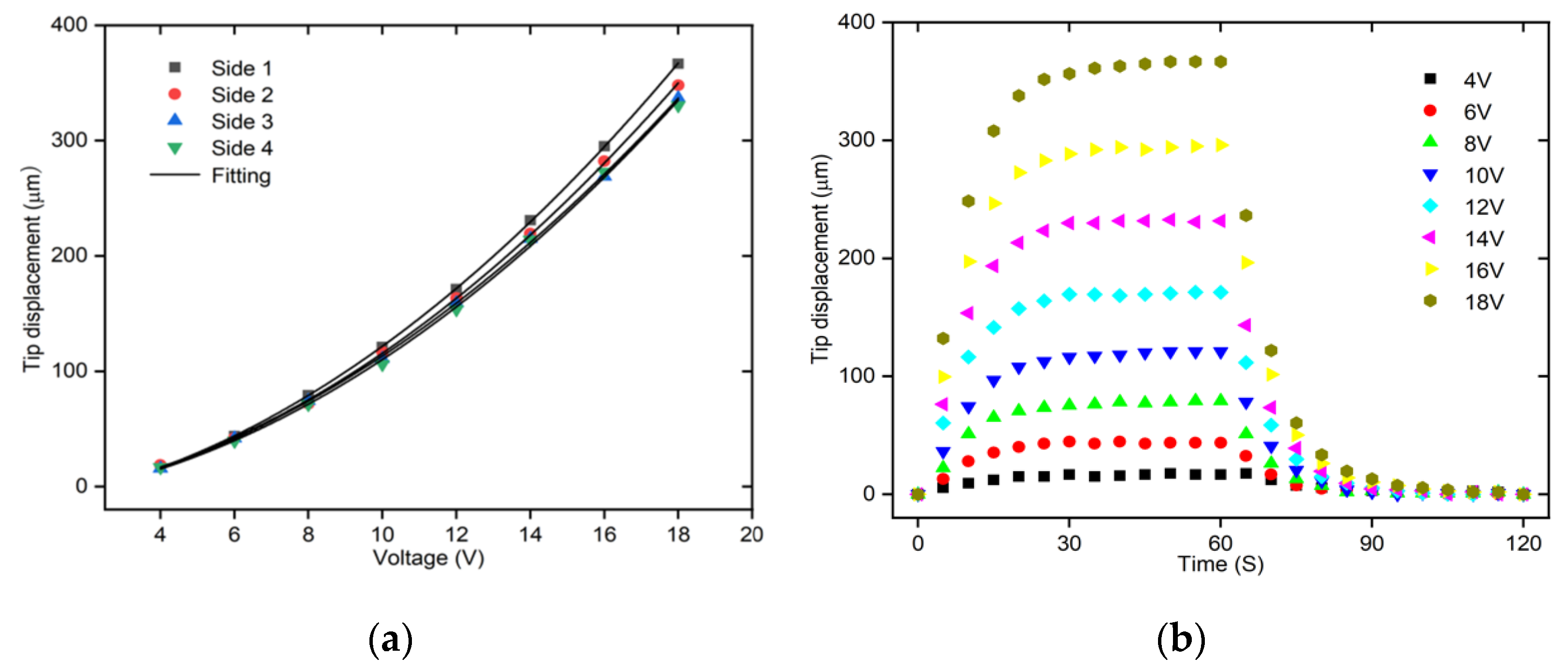
5. Experimental Validation of the Theoretical Model
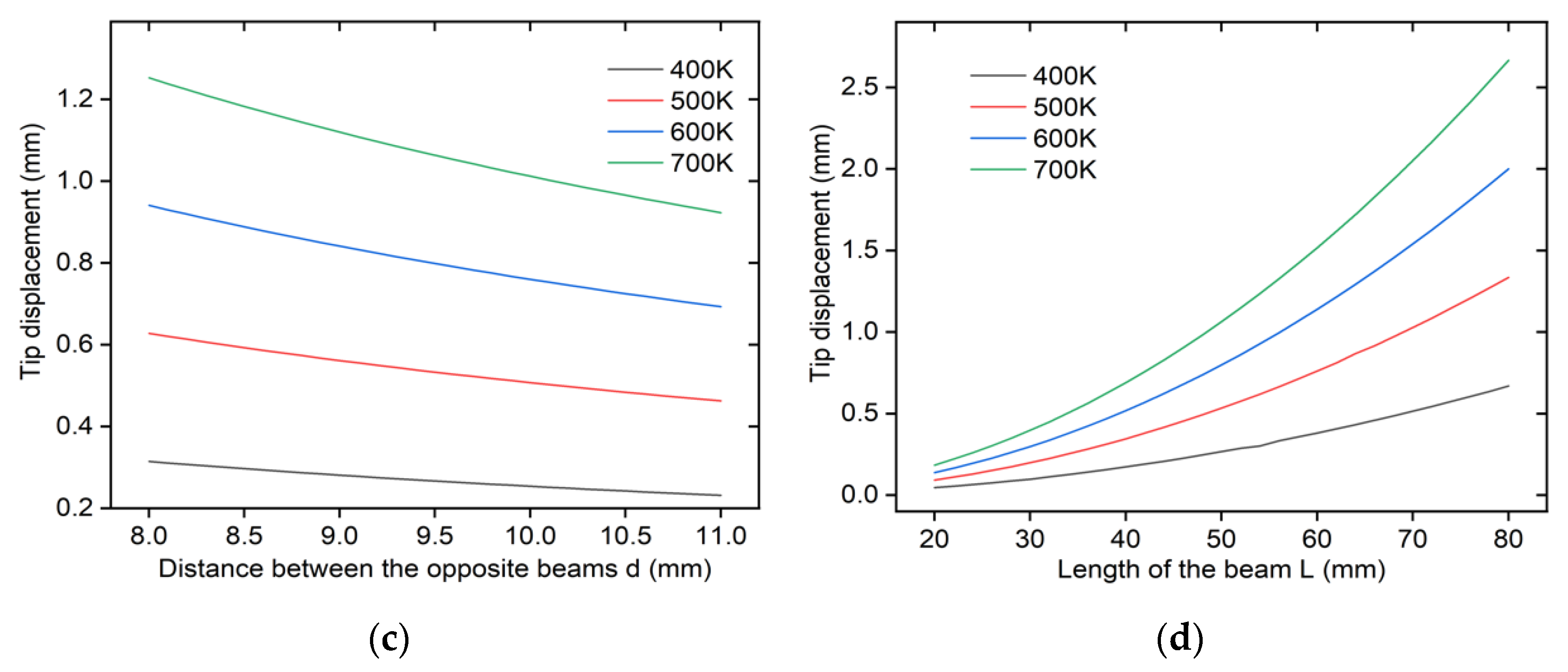
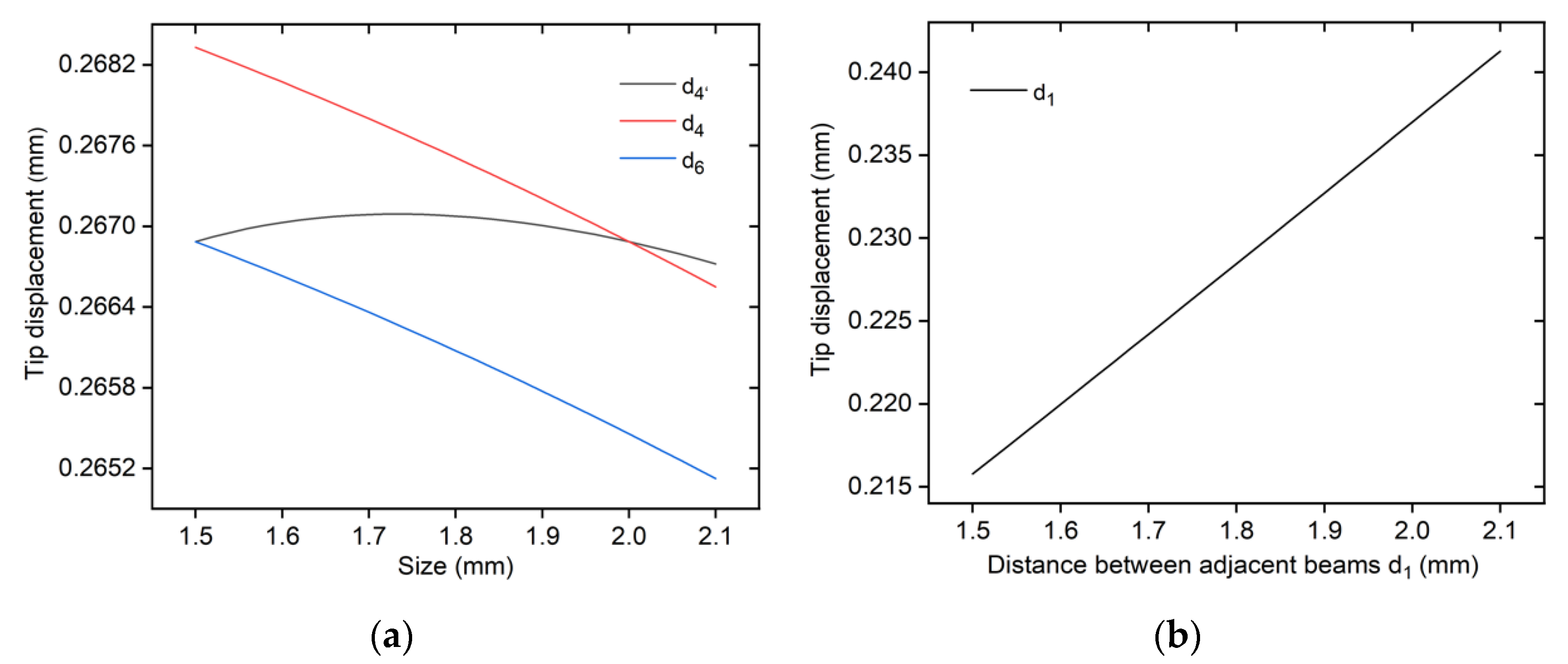
6. Parameter Analyses of the 3D U-Shaped Actuator
7. Testing of the 3D Microgripper
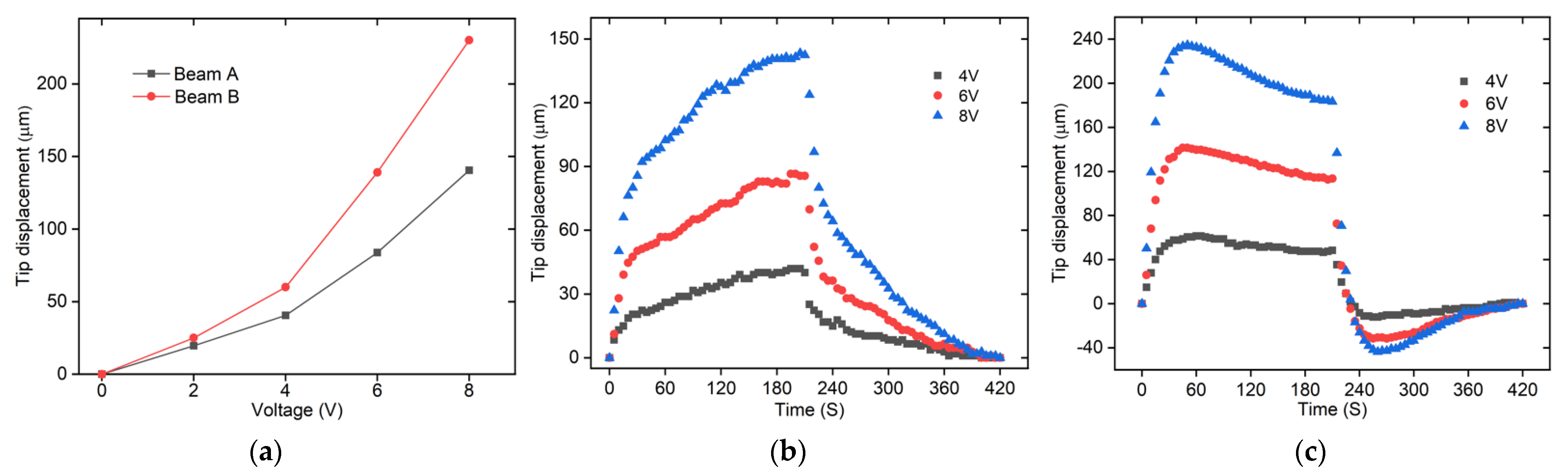
7.1. Testing of the 3D U-Shaped Actuator
7.2. Testing of the Z-Shaped Actuator
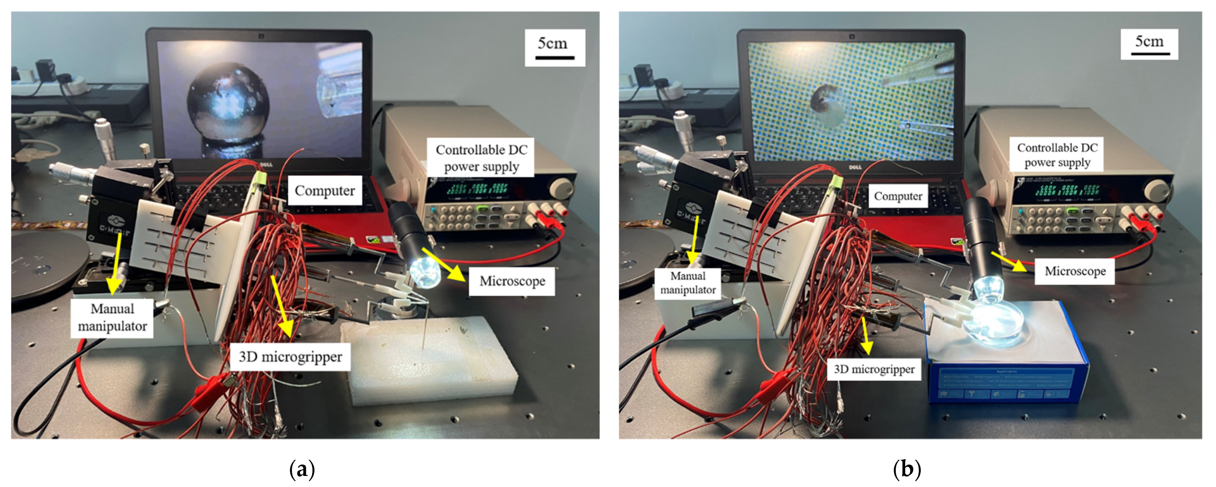
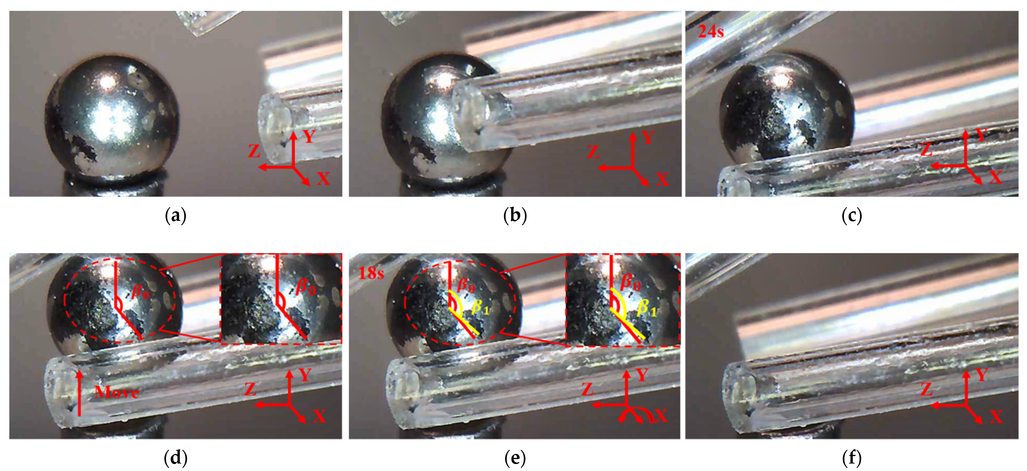
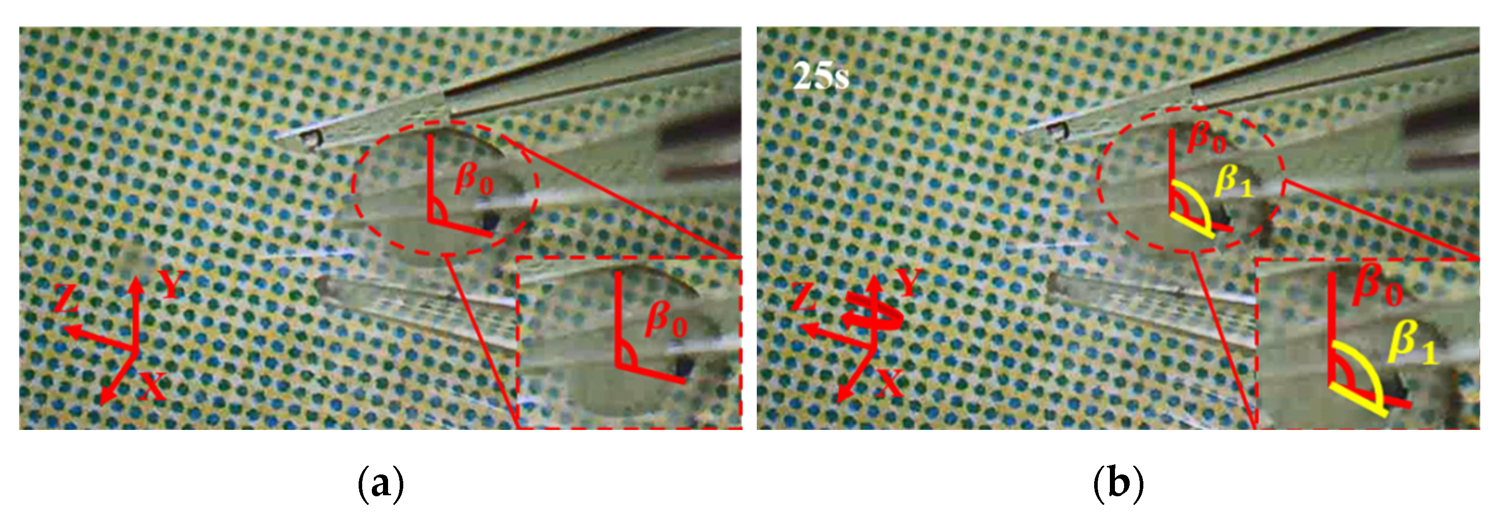
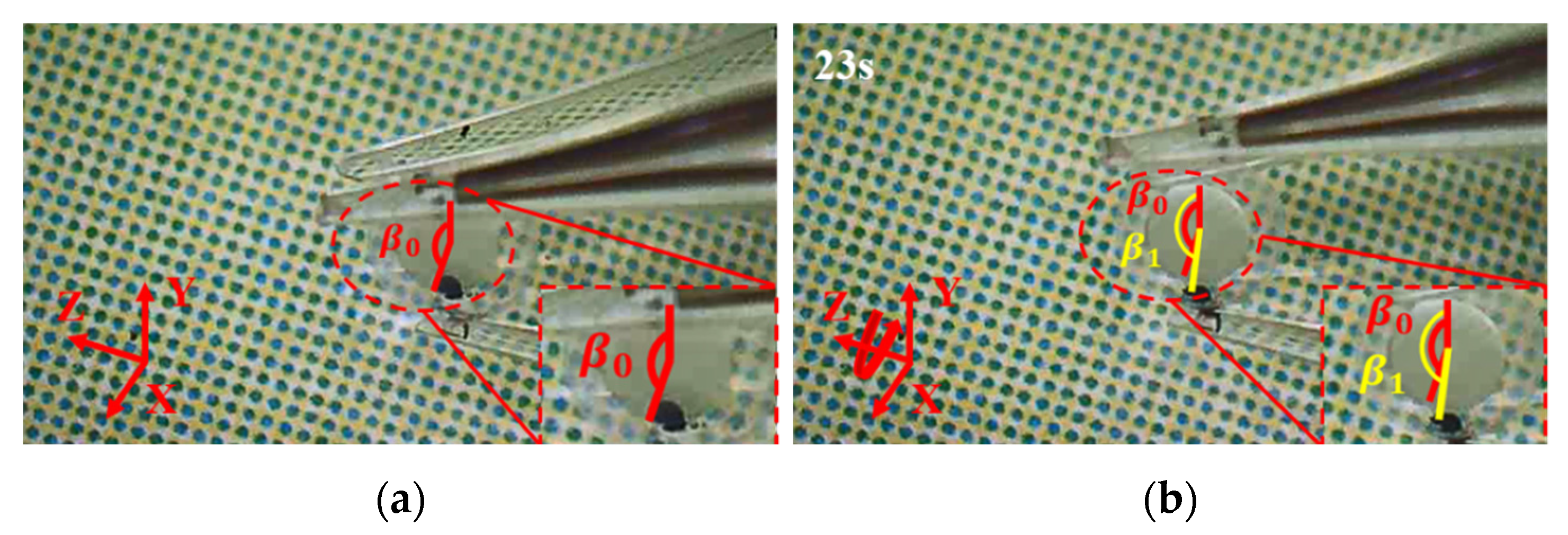
8. Micro-Manipulation Experiments
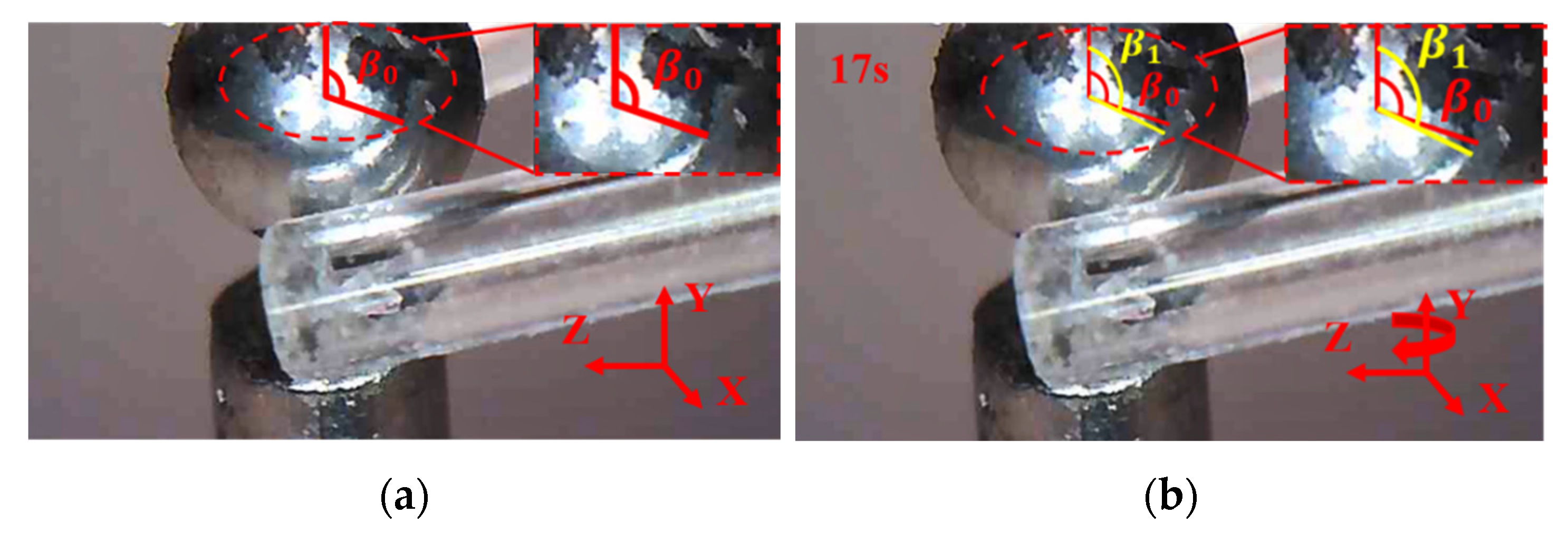
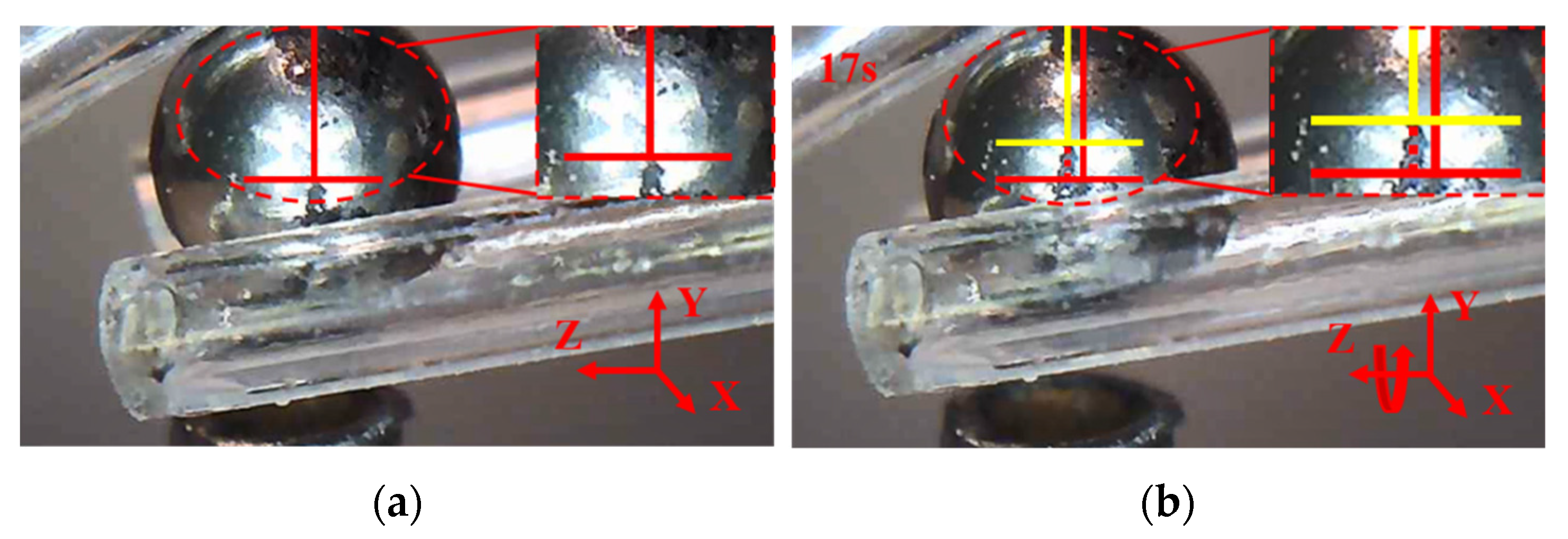
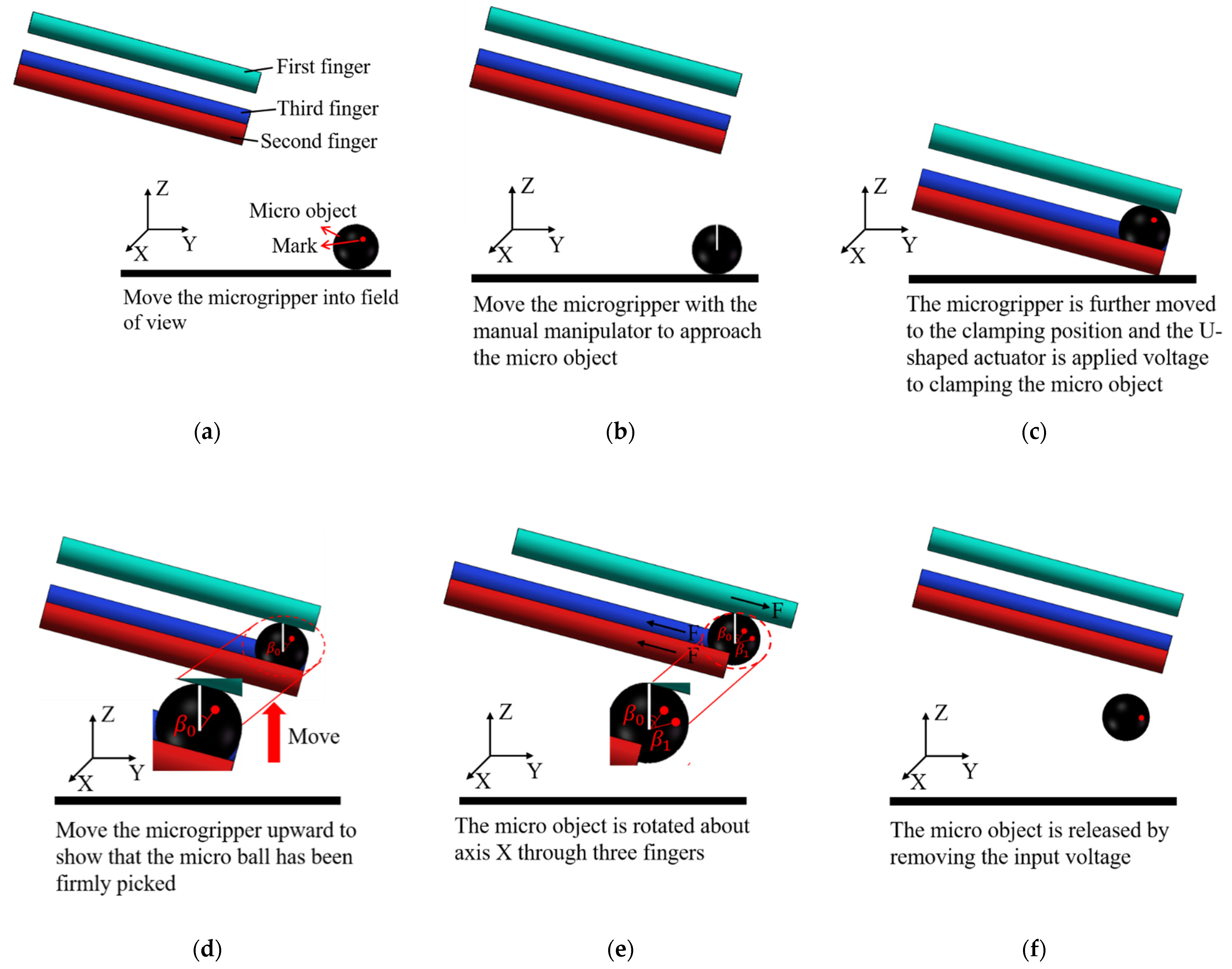
8.1. Manipulations of a Micro Ball
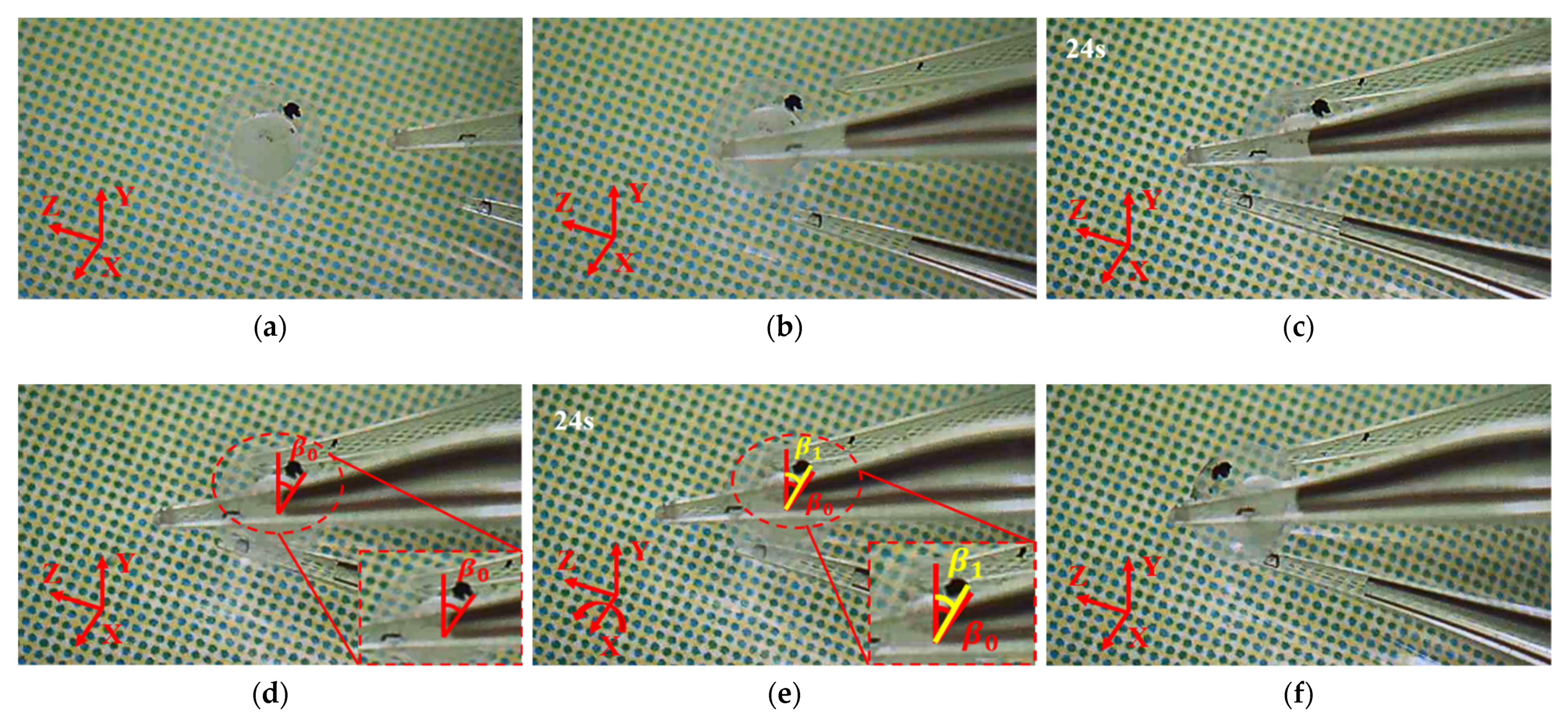
8.2. Manipulations of a Zebrafish Embryo
9. Conclusions
Supplementary Materials
Author Contributions
Funding
Institutional Review Board Statement
Informed Consent Statement
Data Availability Statement
Conflicts of Interest
Appendix A. Elongation and Deflection of a Cantilever Beam


References
- Bettahar, H.; Clévy, C.; Courjal, N.; Lutz, P. Force-Position Photo-Robotic Approach for the High-Accurate Micro-Assembly of Photonic Devices. IEEE Robot. Autom. Lett. 2020, 5, 6396–6402. [Google Scholar] [CrossRef]
- Li, Y.; Zhang, Z.; Ye, X.; Chen, S. A novel micro-assembly method based on the mapping between assembly force and position. Int. J. Adv. Manuf. Technol. 2016, 86, 227–236. [Google Scholar] [CrossRef]
- Xu, Q. Design and Development of a Novel Compliant Gripper with Integrated Position and Grasping/Interaction Force Sensing. IEEE Trans. Autom. 2017, 14, 1415–1428. [Google Scholar] [CrossRef]
- Wu, W.; Peng, H.; Jia, Y.; Jiang, B. Characteristics and mechanisms of polymer interfacial friction heating in ultrasonic plasticization for micro injection molding. Microsyst. Technol. 2017, 23, 1385–1392. [Google Scholar] [CrossRef]
- Tosello, G.; Costa, F.S. High precision validation of micro injection molding process simulations. J. Manuf. Process. 2019, 48, 236–248. [Google Scholar] [CrossRef]
- Masato, D.; Sorgato, M.; Lucchetta, G. Characterization of the micro injection-compression molding process for the replication of high aspect ratio micro-structured surfaces. Microsyst. Technol. 2017, 23, 3661–3670. [Google Scholar] [CrossRef]
- Feng, X.; Li, J.; Zhang, X.; Liu, T.; Ding, J.; Chen, X. Electrospun polymer micro/nanofibers as pharmaceutical repositories for healthcare. J. Control. Release 2019, 302, 19–41. [Google Scholar] [CrossRef] [PubMed]
- Power, M.; Thompson, A.J.; Anastasova, S.; Yang, G.Z. A Monolithic Force-Sensitive 3D Microgripper Fabricated on the Tip of an Optical Fiber Using 2-Photon Polymerization. Small 2018, 14, 1002–1011. [Google Scholar] [CrossRef] [PubMed] [Green Version]
- Neglia, G.; Nicola, D.; Esposito, L.; Salzano, A.; D’Occhio, M.; Fatone, G. Reproductive management in buffalo by artificial insemination. Theriogenology 2020, 150, 166–172. [Google Scholar] [CrossRef] [PubMed]
- Ali, K.M.; Iman, H.; Shahin, G.; Hossein, R.M. Performing ICSI with commercial microinjection pipettes enhanced pregnancy rates. Turk. J. Med. Sci. 2017, 47, 801–805. [Google Scholar] [CrossRef] [Green Version]
- Schoevaerdts, L.; Esteveny, L.; Gijbels, A.; Smits, J.; Reynaerts, D.; Pooten, E. Design and evaluation of a new bioelectrical impedance sensor for micro-surgery: Application to retinal vein cannulation. Int. J. Comput. Assist. Radiol. Surg. 2019, 14, 311–320. [Google Scholar] [CrossRef] [PubMed]
- Serra-Aracil, X.; Serra-Pla, S.; Mora-Lopez, L.; Pallisera-Lloveras, A.; Labro-Ciurans, M.; Navarro-Soto, S. Transanal endoscopic micro-surgery in elderly and very elderly patients: A safe option? Observational study with prospective data collection. Surg. Endosc. 2019, 33, 184–191. [Google Scholar] [CrossRef] [PubMed]
- Lo, S.; Yen, Y.; Lee, P.; Liu, C.; Pu, C. Factors Influencing Postoperative Complications in Reconstructive Microsurgery for Head and Neck Cancer. J. Oral Maxillofac. Surg. 2017, 75, 867–873. [Google Scholar] [CrossRef] [PubMed]
- Song, Y.; An, Y.; Liu, W.; Hou, X.; Li, X.; Lin, B.; Zhu, Z.; Ge, S.; Yang, H.; Yang, C. Centrifugal Micropipette-Tip with Pressure Signal Readout for Portable Quantitative Detection of Myoglobin. Chem. Commun. 2017, 53, 11774–11777. [Google Scholar] [CrossRef] [PubMed]
- Tuzen, M. A new portable switchable hydrophilicity microextraction method for determination of vanadium in microsampling micropipette tip syringe system couple with ETAAS. Talanta 2018, 194, 991–996. [Google Scholar] [CrossRef]
- Backholm, M.; Bäumchen, O. Micropipette force sensors for in vivo force measurements on single cells and multicellular microorganisms. Nat. Protoc. 2019, 14, 594–615. [Google Scholar] [CrossRef] [PubMed] [Green Version]
- Martinez, V.; Han, H.; Vörös, J.; Zambelli, T. SU-8 Micropipettes for Gentle Single-cell Manipulation. Chim. Int. J. Chem. 2019, 73, 1033. [Google Scholar] [CrossRef] [PubMed]
- Mehrabi, H.; Aminzahed, I. Design and testing of a microgripper with SMA actuator for manipulation of micro components. Microsyst Technol. 2020, 26, 531–536. [Google Scholar] [CrossRef]
- Shivhare, P.; Uma, G.; Umapathy, M. Design enhancement of a chevron electrothermally actuated microgripper for improved gripping performance. Microsyst Technol. 2016, 22, 2623–2631. [Google Scholar] [CrossRef]
- Ruggeri, S.; Fontana, G.; Legnani, G.; Fassi, I. Performance Indices for the Evaluation of Microgrippers Precision in Grasping and Releasing Phases. Int. J. Precis. Eng. Manuf. 2019, 20, 2141–2153. [Google Scholar] [CrossRef]
- Gaafar, E.; Zarog, M. A low-stress and low temperature gradient microgripper for biomedical applications. Microsyst. Technol. 2017, 23, 5415–5422. [Google Scholar] [CrossRef]
- Chen, T.; Wang, Y.; Zhan, Y.; Liu, H.; Sun, L. A PZT Actuated Triple-Finger Gripper for Multi-Target Micromanipulation. Micromachines 2017, 8, 33. [Google Scholar] [CrossRef] [Green Version]
- Mehrabi, H.; Hamedi, M.; Aminzahed, I. A novel design and fabrication of a micro-gripper for manipulation of micro-scale parts actuated by a bending piezoelectric. Microsyst. Technol. 2020, 26, 1563–1571. [Google Scholar] [CrossRef]
- Zhang, Z.; Yu, Y.; Song, P.; Zhang, Y.; Tian, D. Automated manipulation of zebrafish embryos using an electrothermal microgripper. Microsyst. Technol. 2020, 26, 1823–1834. [Google Scholar] [CrossRef]
- Al-Zandi, M.; Wang, C.; Voicu, R.; Muller, R. Measurement and characterisation of displacement and temperature of polymer based electrothermal microgrippers. Microsyst. Technol. 2018, 24, 379–387. [Google Scholar] [CrossRef]
- Cauchi, M.; Grech, I.; Mallia, B.; Mollicone, P.; Sammut, N. The Effects of Structure Thickness, Air Gap Thickness and Silicon Type on the Performance of a Horizontal Electrothermal MEMS Microgripper. Actuators 2018, 7, 38. [Google Scholar] [CrossRef] [Green Version]
- Feng, Y.Y.; Chen, S.J.; Hsieh, P.H.; Chu, W.T. Fabrication of an electro-thermal micro-gripper with elliptical cross-sections using silver-nickel composite ink. Sens. Actuator A Phys. 2016, 245, 106–112. [Google Scholar] [CrossRef]
- Dodd, L.E.; Ward, S.C.; Cooke, M.D.; Wood, D. The static and dynamic response of SU-8 electrothermal microgrippers of varying thickness. Microelectron. Eng. 2015, 145, 82–85. [Google Scholar] [CrossRef] [Green Version]
- Masood, M.U.; Saleem, M.M.; Khan, U.S.; Hamza, A. Design, closed-form modeling and analysis of SU-8 based electrothermal microgripper for biomedical applications. Microsyst. Technol. 2019, 25, 1171–1184. [Google Scholar] [CrossRef]
- Wang, Z.; Shen, X.; Chen, X. Design, modeling, and characterization of a MEMS electrothermal microgripper. Microsyst. Technol. 2015, 21, 2307–2314. [Google Scholar] [CrossRef]
- Potekhina, A.; Voicu, R.C.; Muller, R.; Al-Zandi, M.; Wang, C. Design and characterization of a polymer electrothermal microgripper with a polynomial flexure for efficient operation and studies of moisture effect on negative deflection. Microsyst. Technol. 2021, 27, 2723–2731. [Google Scholar] [CrossRef]
- Si, G.; Sun, L.; Zhang, Z.; Zhang, X. Design, fabrication, and testing of a novel 3D 3-fingered electrothermal microgripper with multiple degrees of freedom. Micromachines 2021, 12, 444. [Google Scholar] [CrossRef]
- Chen, W.S.; Liu, Y.Y.; Liu, Y.X.; Tian, X.; Shan, X.B.; Wang, L. Design and experimental evaluation of a novel stepping linear piezoelectric actuator. Sens. Actuator A Phys. 2018, 276, 259–266. [Google Scholar] [CrossRef]
- Estahbanati, S.; Dhaouadi, R.; Bakri-Kassem, M. Macromodeling of thermally driven V-shaped MEMS actuators. Mechatronics 2017, 46, 193–204. [Google Scholar] [CrossRef]
- Nguyen, D.T.; Hoang, K.T.; Pham, P.H. Larger displacement of silicon electrothermal V-shaped actuator using surface sputtering process. Microsyst. Technol. 2021, 27, 1985–1991. [Google Scholar] [CrossRef]
- Llewellyn-Evans, H.; Griffiths, C.A.; Fahmy, A. Microgripper design and evaluation for automated µ-wire assembly: A survey. Microsyst. Technol. 2020, 26, 1745–1768. [Google Scholar] [CrossRef] [Green Version]
- Somà, A.; Iamoni, S.; Voicu, R.; Müller, R.; Al-Zandi, M.; Wang, C. Design and experimental testing of an electro-thermal microgripper for cell manipulation. Microsyst. Technol. 2018, 24, 1053–1060. [Google Scholar] [CrossRef]
- Pustan, M.; Chiorean, R.; Birleanu, C.; Dudescu, C.; Muller, R.; Baracu, A.; Voicu, R. Reliability design of thermally actuated MEMS switches based on V-shape beams. Microsyst. Technol. 2017, 23, 3863–3871. [Google Scholar] [CrossRef]
- Sevim, S.; Tolunay, S.; Torun, H. Micromachined sample stages to reduce thermal drift in atomic force microscopy. Microsyst. Technol. 2015, 21, 1559–1566. [Google Scholar] [CrossRef]
- Zhang, Z.; Wu, Q.; Yu, Y.; Zhang, X. A comprehensive analytical model and experimental validation of Z-shaped electrothermal microactuators. Springer Ser. Surf. Sci. 2015, 33, 177–187. [Google Scholar] [CrossRef]


| Challenge | Address the Challenge |
|---|---|
| A planar microgripper with multi-DOFs only brings the flexibility for the planar manipulation of microobjects | A three-finger microgripper that can operate micro objects in space is proposed. |
| A multi-finger microgripper has only one DOF for each finger | A three-finger microgripper with multiple DOFs for each finger is proposed. |
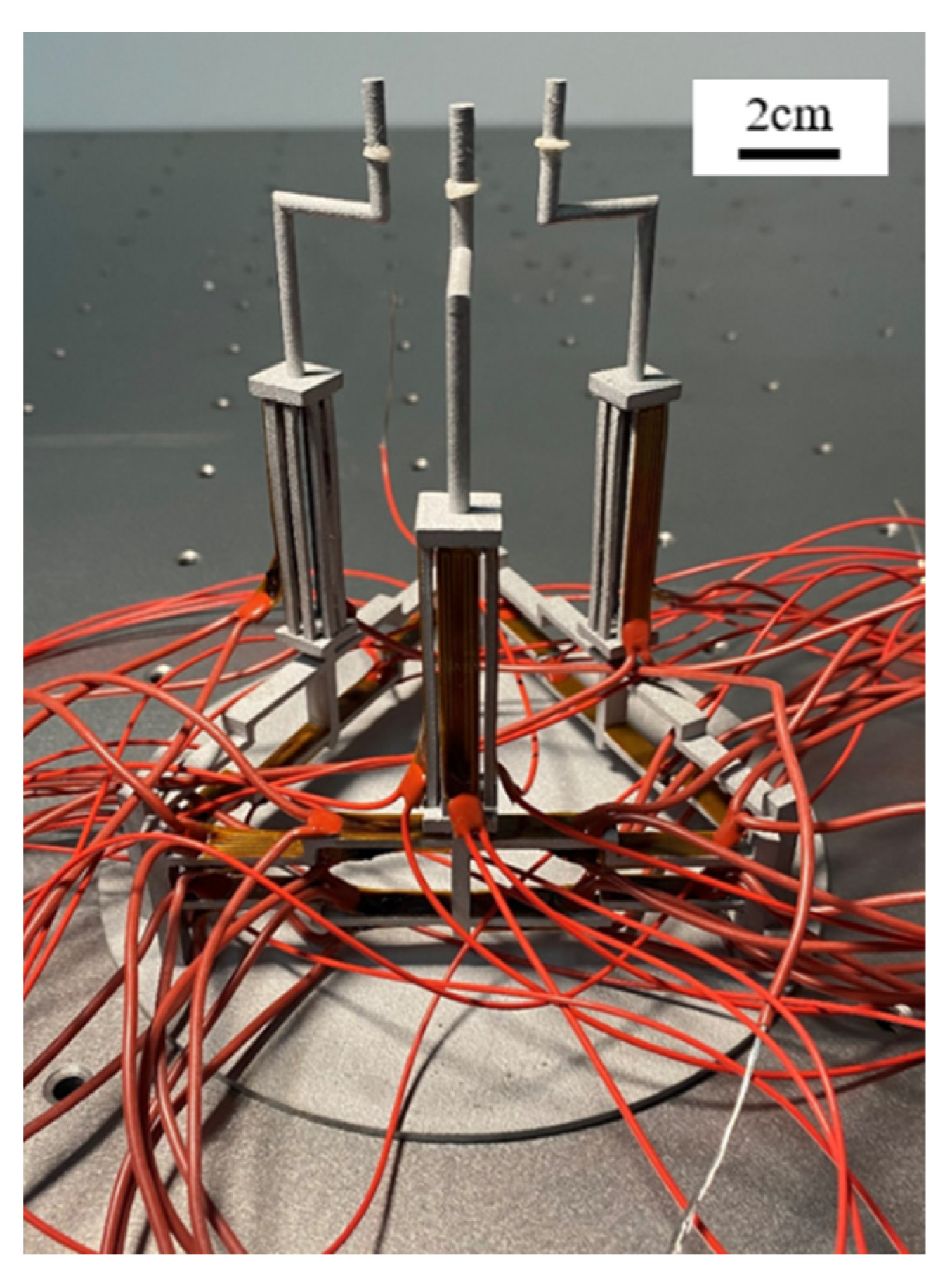
| Design and manufacture of the 3-fingers electrothermal microgripper | A novel 3D electro-thermal microgripper that can provide multi DOFs with three fingers is designed. Each finger is composed of a novel 3D U-shaped actuator and a bi-directional Z-shaped actuator. Besides, the microgripper is processed integrally by 3D printing. |
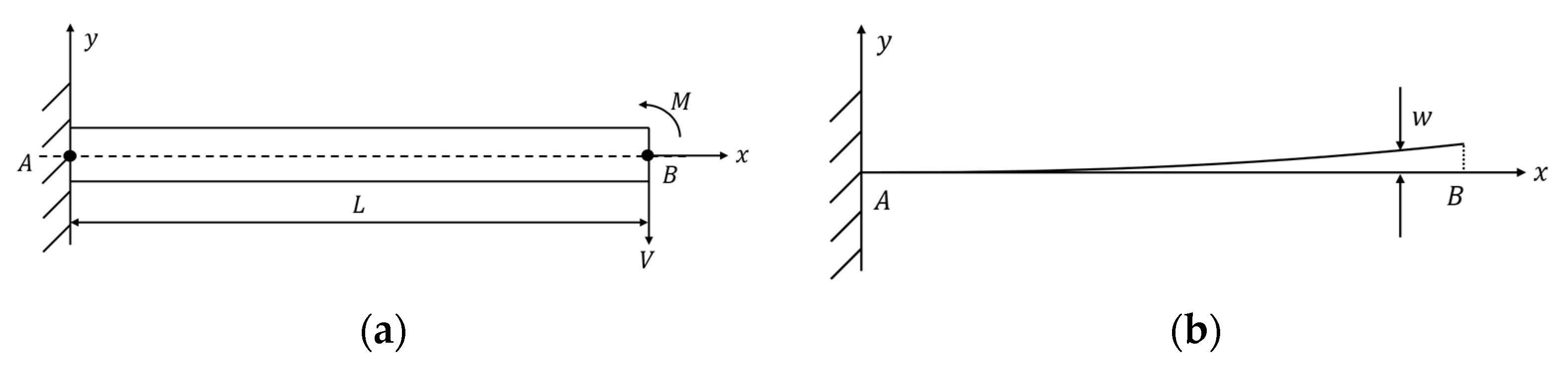
| The static theoretical model of 3D U-shaped actuator is deduced. | The theoretical relationship between the input temperature load and the output displacement of 3D U-shaped electrothermal actuator is deduced by using the superposition principle and deflection formula. |
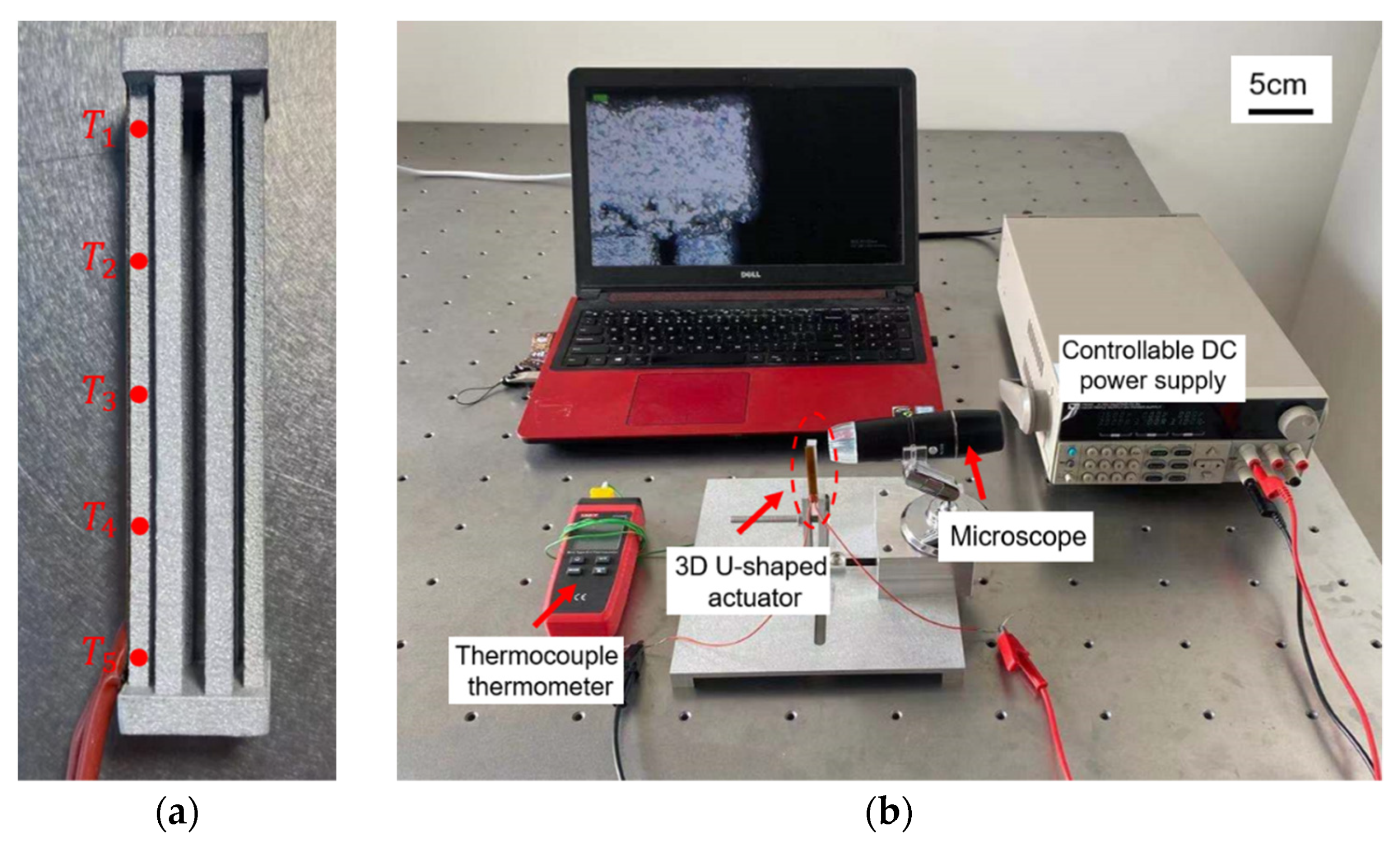
| Measure the temperature of the beams of the 3D U-shaped actuator. | The average beams temperature is obtained by taking the average measured temperatures of many measuring points. |
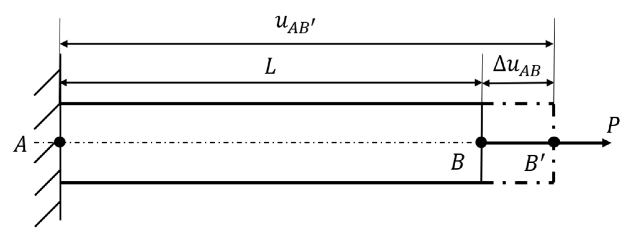
| Due to manufacturing limitations, the dimension of the microgripper tip is larger than the micro object. | The glass capillary is assembled with the tip of the microgripper to operate the micro object. |
| Symbol | Definition | Value |
|---|---|---|
| Distance between two opposite beams | 9.5 | |
| Distance between two adjacent beams in the different direction | 2.75 | |
| Distance between two adjacent beams in the same direction | 4 | |
| Distance between the beam and base boundary | 3 | |
| Width of the beam | 2 | |
| Length of base | 12 | |
| Thickness of beam | 1.5 | |
| Distance between beam and base boundary | 0.5 | |
| Height of the base | 3 | |
| Length of the beam | 50 |
| External Load (N) | Temperature (K) | Tip Displacement (mm) | Error (%) | |
|---|---|---|---|---|
| F = 0 | 400 | 0.2669 | 0.2649 | 0.7493 |
| 500 | 0.5331 | 0.5298 | 0.6190 | |
| 600 | 0.7986 | 0.7947 | 0.4884 | |
| 700 | 1.0635 | 1.0596 | 0.3667 | |
| F = 0.1N | 400 | 0.2649 | 0.2619 | 1.1325 |
| 500 | 0.5311 | 0.5268 | 0.8096 | |
| 600 | 0.7966 | 0.7917 | 0.6151 | |
| 700 | 1.0615 | 1.0566 | 0.4616 | |
| F = K*Δ | 400 | 0.2665 | 0.2647 | 0.6754 |
| 500 | 0.5323 | 0.5293 | 0.5636 | |
| 600 | 0.7973 | 0.7940 | 0.4139 | |
| 700 | 1.0617 | 1.0586 | 0.2920 | |
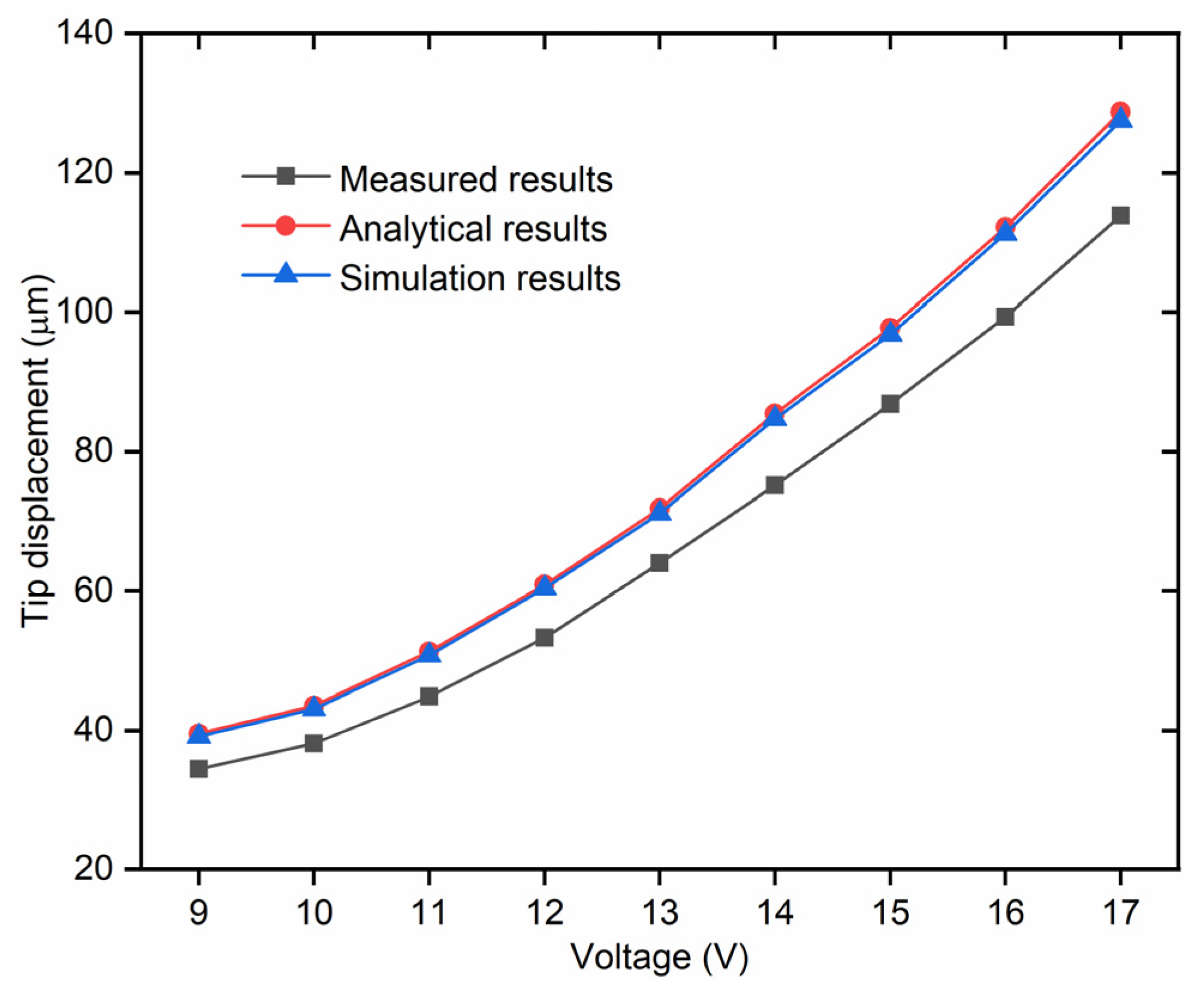
| Input Voltage (V) | Average Temperature Rise (°C) | Measured (μm) | Analytical (μm) | Deviation (%) |
|---|---|---|---|---|
| 9 | 14.8 | 34.463 | 39.544 | 12.849 |
| 10 | 16.3 | 38.157 | 43.551 | 12.385 |
| 11 | 19.2 | 44.867 | 51.297 | 12.535 |
| 12 | 22.8 | 53.281 | 60.913 | 12.529 |
| 13 | 26.9 | 64.013 | 71.862 | 10.922 |
| 14 | 32 | 75.151 | 85.481 | 12.085 |
| 15 | 36.6 | 86.853 | 97.762 | 11.159 |
| 16 | 42 | 99.349 | 112.178 | 11.436 |
| 17 | 48.2 | 113.884 | 128.727 | 11.531 |
| Parameter | The Displacement |
|---|---|
| Length of beam | Polynomially increase with |
| Width of beam | Polynomially decrease with |
| Thickness of beam | Polynomially decease with |
| Distance from beam | Polynomially decease with d |
| Distance between adjacent beams | Linearly increase with |
| When the area is constant, the width of the beam | Polynomially increasing first and then decreasing with |
Publisher’s Note: MDPI stays neutral with regard to jurisdictional claims in published maps and institutional affiliations. |
© 2021 by the authors. Licensee MDPI, Basel, Switzerland. This article is an open access article distributed under the terms and conditions of the Creative Commons Attribution (CC BY) license (https://creativecommons.org/licenses/by/4.0/).
Share and Cite
Si, G.; Sun, L.; Zhang, Z.; Zhang, X. Theoretical Thermal-Mechanical Modelling and Experimental Validation of a Three-Dimensional (3D) Electrothermal Microgripper with Three Fingers. Micromachines 2021, 12, 1512. https://doi.org/10.3390/mi12121512
Si G, Sun L, Zhang Z, Zhang X. Theoretical Thermal-Mechanical Modelling and Experimental Validation of a Three-Dimensional (3D) Electrothermal Microgripper with Three Fingers. Micromachines. 2021; 12(12):1512. https://doi.org/10.3390/mi12121512
Chicago/Turabian StyleSi, Guoning, Liangying Sun, Zhuo Zhang, and Xuping Zhang. 2021. "Theoretical Thermal-Mechanical Modelling and Experimental Validation of a Three-Dimensional (3D) Electrothermal Microgripper with Three Fingers" Micromachines 12, no. 12: 1512. https://doi.org/10.3390/mi12121512