
Advanced Infill Designs for 3D Printed Shape-Memory Components


Abstract
:1. Introduction
2. Materials and Methods
- -
- The inner walls are thinner, enabled by printing on a long thin plane (front or back in the sliced models in Table 1), thus reducing the specimen’s mass.
- -
- -
- Special lightweight designs are used (samples A and C), again reducing the specimen’s mass.
- -
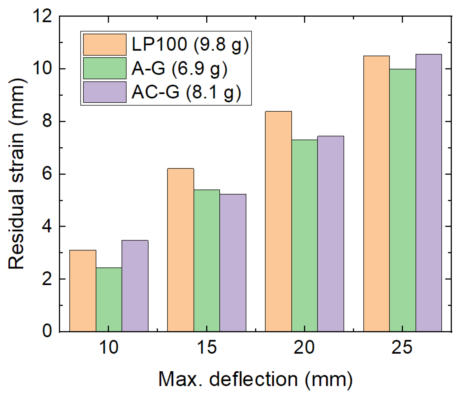
- All samples are more lightweight than the best specimen of the previous study (sample LP100 in [18] had a mass of 9.8 g).
3. Results and Discussion
4. Conclusions
Author Contributions
Funding
Institutional Review Board Statement
Informed Consent Statement
Data Availability Statement
Conflicts of Interest
References
- Noorani, R. Rapid Prototyping: Principles and Applications; John Wiley & Sons: Hoboken, NJ, USA, 2005. [Google Scholar]
- Wickramasinghe, S.; Do, T.; Tran, P. FDM-based 3D printing of polymer and associated composite: A review on mechanical properties, defects and treatments. Polymers 2020, 12, 1529. [Google Scholar] [CrossRef]
- Garzon-Hernandez, S.; Garcia-Gonzalez, D.; Jérusalemn, A.; Arias, A. Design of FDM 3D printed polymers: An experimental-modelling methodology for the prediction of mechanical properties. Mater. Design 2020, 188, 108414. [Google Scholar] [CrossRef]
- Wan, M.L.; Liu, S.F.; Huang, D.; Qu, Y.; Hu, Y.; Su, Q.S.; Zheng, W.X.; Dong, X.M.; Zhang, H.W.; Wei, Y.; et al. Biocompatible heterogeneous bone incorporated with polymeric biocomposites for human bone repair by 3D printing technology. J. Appl. Polym. Sci. 2020, 138, e50114. [Google Scholar] [CrossRef]
- Sölmann, S.; Rattenholl, A.; Blattner, H.; Ehrmann, G.; Gudermann, F.; Lütkemeyer, D.; Ehrmann, A. Mammalian cell adhesion on different 3D printed polymers with varying sterilization methods and acidic treatment. AIMS Bioeng. 2021, 8, 25–35. [Google Scholar]
- Wu, W.Z.; Ye, W.L.; Wu, Z.C.; Geng, P.; Wang, Y.L.; Zhao, J. Influence of layer thickness, raster angle, deformation temperature and recovery temperature on the shape-memory effect of 3D-printed polylactic acid samples. Materials 2017, 10, 970. [Google Scholar] [CrossRef] [PubMed] [Green Version]
- Ehrmann, G.; Ehrmann, A. 3D printing of shape memory properties. J. Appl. Polym. Sci. 2021, 138, e50847. [Google Scholar] [CrossRef]
- Ehrmann, G.; Ehrmann, A. Pressure orientation dependent recovery of 3D-printed PLA objects with varying infill degree. Polymers 2021, 13, 1275. [Google Scholar] [CrossRef]
- Chalgham, A.; Wickenkamp, I.; Ehrmann, A. Mechanical properties of FDM printed PLA parts before and after thermal treatment. Polymers 2021, 13, 1239. [Google Scholar] [CrossRef] [PubMed]
- Senatov, F.S.; Niaza, N.K.; Zadorozhnyy, M.Y.; Maksimkin, A.V.; Kaloshkin, S.D.; Estrin, Y.Z. Mechanical properties and shape memory effect of 3D-printed PLA-based porous scaffolds. J. Mech. Behav. Biomed. Mater. 2016, 57, 139–148. [Google Scholar] [CrossRef] [PubMed]
- Lendlein, A.; Langer, R. Biodegradable, elastic shape-memory polymers for potential biomedical applications. Science 2002, 296, 1673–1676. [Google Scholar] [CrossRef]
- Senatov, F.S.; Zadorozhnyy, M.Y.; Niaza, K.V.; Medvedev, V.V.; Kaloshkin, S.D.; Anisimova, N.Y.; Kiselevskiy, M.V.; Yang, K.-C. Shape memory effect in 3D-printed scaffolds for self-fitting implants. Eur. Polym. J. 2017, 93, 222–231. [Google Scholar] [CrossRef]
- Langford, T.; Mohammed, A.; Essa, K.; Elshaer, A.; Hassanin, H. 4D printing of origami structures for minimally invasive surgeries using functional scaffold. Appl. Sci. 2021, 11, 332. [Google Scholar] [CrossRef]
- Koch, H.C.; Schmelzeisen, D.; Gries, T. 4D textiles made by additive manufacturing on pre-stressed textiles—An overview. Actuators 2021, 10, 31. [Google Scholar] [CrossRef]
- Mohol, S.S.; Sharma, V. Functional applications of 4D printing: A review. Rapid Prototyp. J. 2021, 27, 1501–1522. [Google Scholar] [CrossRef]
- Kumar, S.B.; Jeevamalar, J.; Ramu, P.; Suresh, G.; Senthilnathan, K. Evaluation in 4D printing—A review. Mater. Today Proc. 2021, 45, 1433–1437. [Google Scholar] [CrossRef]
- Biswas, M.C.; Chakraborty, S.; Bhattacharjee, A.; Mohammed, Z. 4D printing of shape memory materials for textiles: Mechanism, mathematical modeling, and challenges. Adv. Funct. Mater. 2021, 31, 2011257. [Google Scholar] [CrossRef]
- Koske, D.; Ehrmann, A. Infill design for 3D-printed shape memory objects. Technologies 2021, 9, 29. [Google Scholar] [CrossRef]
- Siemens PLM Software Fortschrittliche Technologie für Generatives Design in NX. Available online: https://docplayer.org/207286426-Siemens-plm-software-fortschrittliche-technologie-fuer-generatives-design-in-nx.html (accessed on 19 September 2021).
- Xiao, R.; Li, X.; Jia, H.; Surjadi, J.U.; Li, J.Q.; Lin, W.T.; Gao, L.B.; Chirarattananon, P.; Lu, Y. 3D printing of dual phase-strengthened microlattices for lightweight micro aerial vehicles. Mater. Design 2021, 206, 109767. [Google Scholar] [CrossRef]
- Prawoto, Y. Seeing auxetic materials from the mechanics point of view: A structural review on the negative Poisson’s ration. Comput. Mater. Sci. 2012, 58, 140–153. [Google Scholar] [CrossRef]
- Li, H.B.; Huneault, M.A. Effect of nucleation and plasticization on the crystallization of poly (lactic acid). Polymer 2007, 48, 6855–6866. [Google Scholar] [CrossRef] [Green Version]
- Müller, A.J.; Ávila, M.; Saenz, G.; Salazar, J. Crystallization of PLA-based materials. In Poly (Lactic Acid) Science and Technology: Processing, Properties, Additives and Applications; Jiménez, A., Peltzer, M., Ruseckaite, R., Eds.; The Royal Society of Chemistry: Cambridge, UK, 2015. [Google Scholar]
- Schneider, C.; Zenkert, D.; Deshpande, V.S.; Kazemahvazi, S. Bending energy absorption of self-reinforced poly (ethylene terephthalate) composite sandwich beams. Compos. Struct. 2016, 140, 582–589. [Google Scholar] [CrossRef] [Green Version]
- Vidakis, N.; Petousis, M.; Velidakis, E.; Liebscher, M.; Mechtcherine, V.; Tzounis, L. On the strain rate sensitivity of fused filament fabrication (FFF) processed PLA, ABS, PETG, PA6, and PP thermoplastic polymers. Polymers 2020, 12, 2924. [Google Scholar] [CrossRef] [PubMed]


| Sample Name (Sample Mass) | Sliced Model | Printed Specimen |
|---|---|---|
| A-k (6.1 g) | 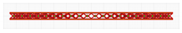 | 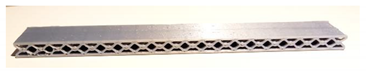 |
| A-G (6.9 g) | 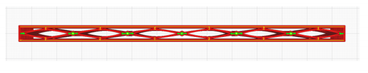 | 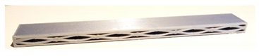 |
| B-G (6.6 g) | 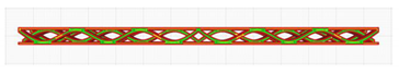 | 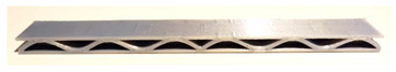 |
| C-k (9.0 g) |  | 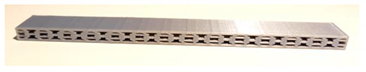 |
| AC-G (8.1 g) | 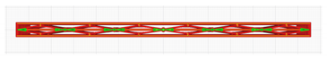 | 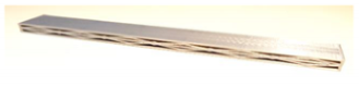 |
| AC-H (9.4 g) | 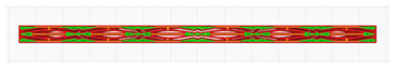 | 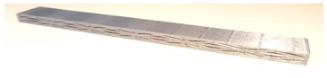 |
| D-G (9.2 g) | 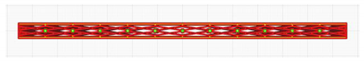 |  |
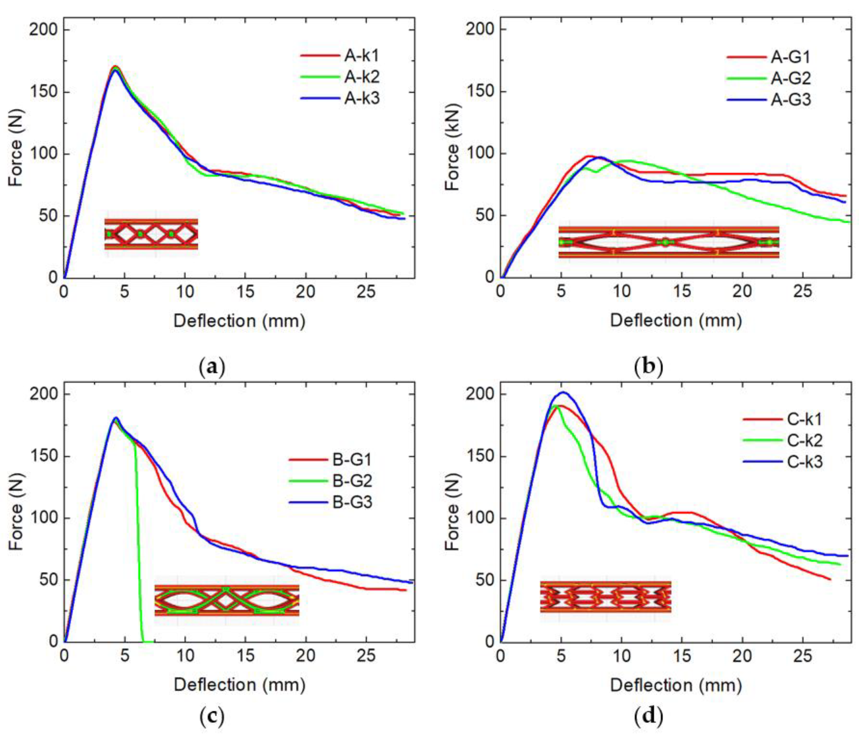
| Sample | Max. Force (N) | Absorbed Energy (J) |
|---|---|---|
| A-k | 169.7 ± 1.5 | 2.47 ± 0.04 |
| A-G | 96.3 ± 2.1 | 1.99 ± 0.12 |
| B-G | 180.0 ± 1.7 | 2.42 ± 0.09 1 |
| C-k | 195 ± 6 | 2.91 ± 0.10 |
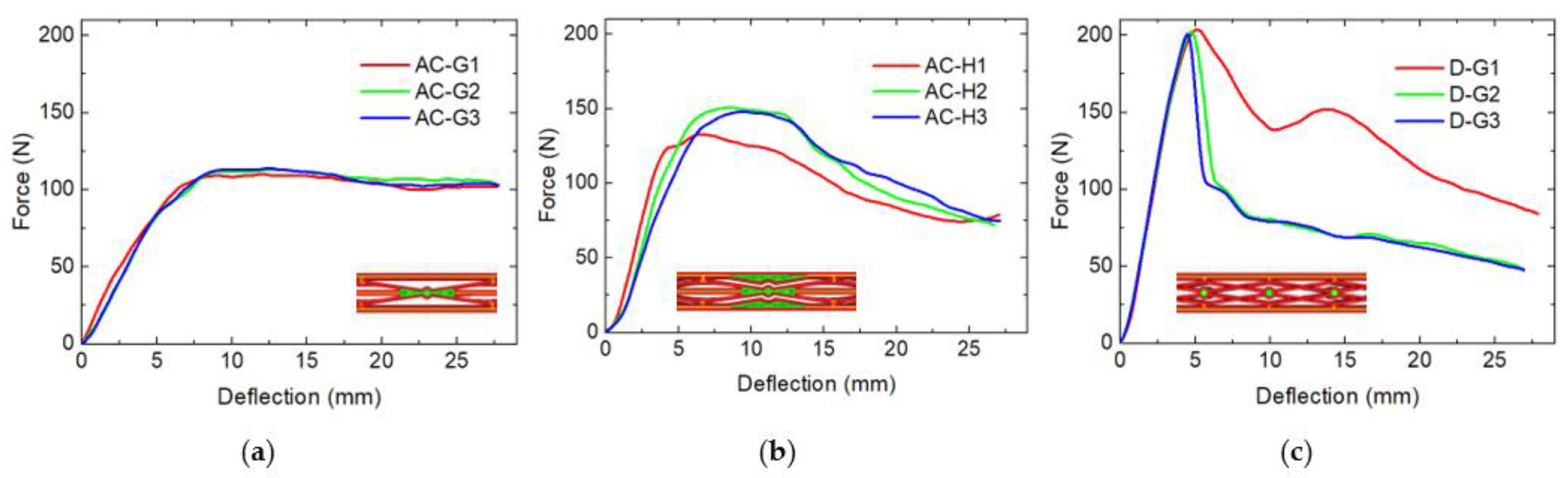
| AC-G | 112.3 ± 2.1 | 2.622 ± 0.010 |
| AC-H | 144 ± 10 | 2.73 ± 0.12 |
| D-G | 206.0 ± 2.0 | 2.6 ± 0.8 |
Publisher’s Note: MDPI stays neutral with regard to jurisdictional claims in published maps and institutional affiliations. |
© 2021 by the authors. Licensee MDPI, Basel, Switzerland. This article is an open access article distributed under the terms and conditions of the Creative Commons Attribution (CC BY) license (https://creativecommons.org/licenses/by/4.0/).
Share and Cite
Koske, D.; Ehrmann, A. Advanced Infill Designs for 3D Printed Shape-Memory Components. Micromachines 2021, 12, 1225. https://doi.org/10.3390/mi12101225
Koske D, Ehrmann A. Advanced Infill Designs for 3D Printed Shape-Memory Components. Micromachines. 2021; 12(10):1225. https://doi.org/10.3390/mi12101225
Chicago/Turabian StyleKoske, Daniel, and Andrea Ehrmann. 2021. "Advanced Infill Designs for 3D Printed Shape-Memory Components" Micromachines 12, no. 10: 1225. https://doi.org/10.3390/mi12101225
APA StyleKoske, D., & Ehrmann, A. (2021). Advanced Infill Designs for 3D Printed Shape-Memory Components. Micromachines, 12(10), 1225. https://doi.org/10.3390/mi12101225