Effect of Ceramic Capillary Parameters on Bonded Morphology and Strength

 ,
,
Abstract
1. Introduction
2. Materials and Methods
2.1. Test Materials
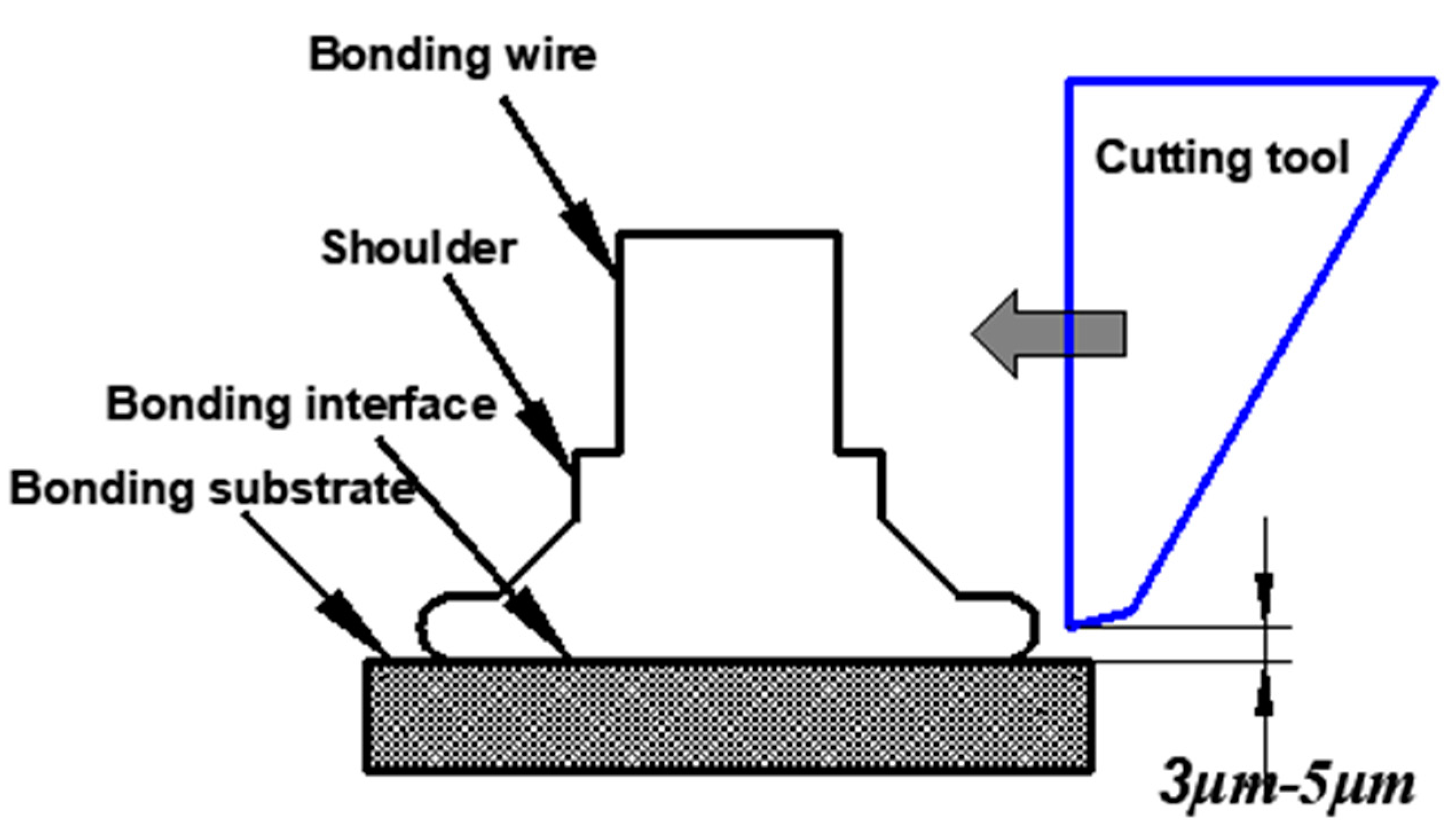
2.2. Test Method
3. Results
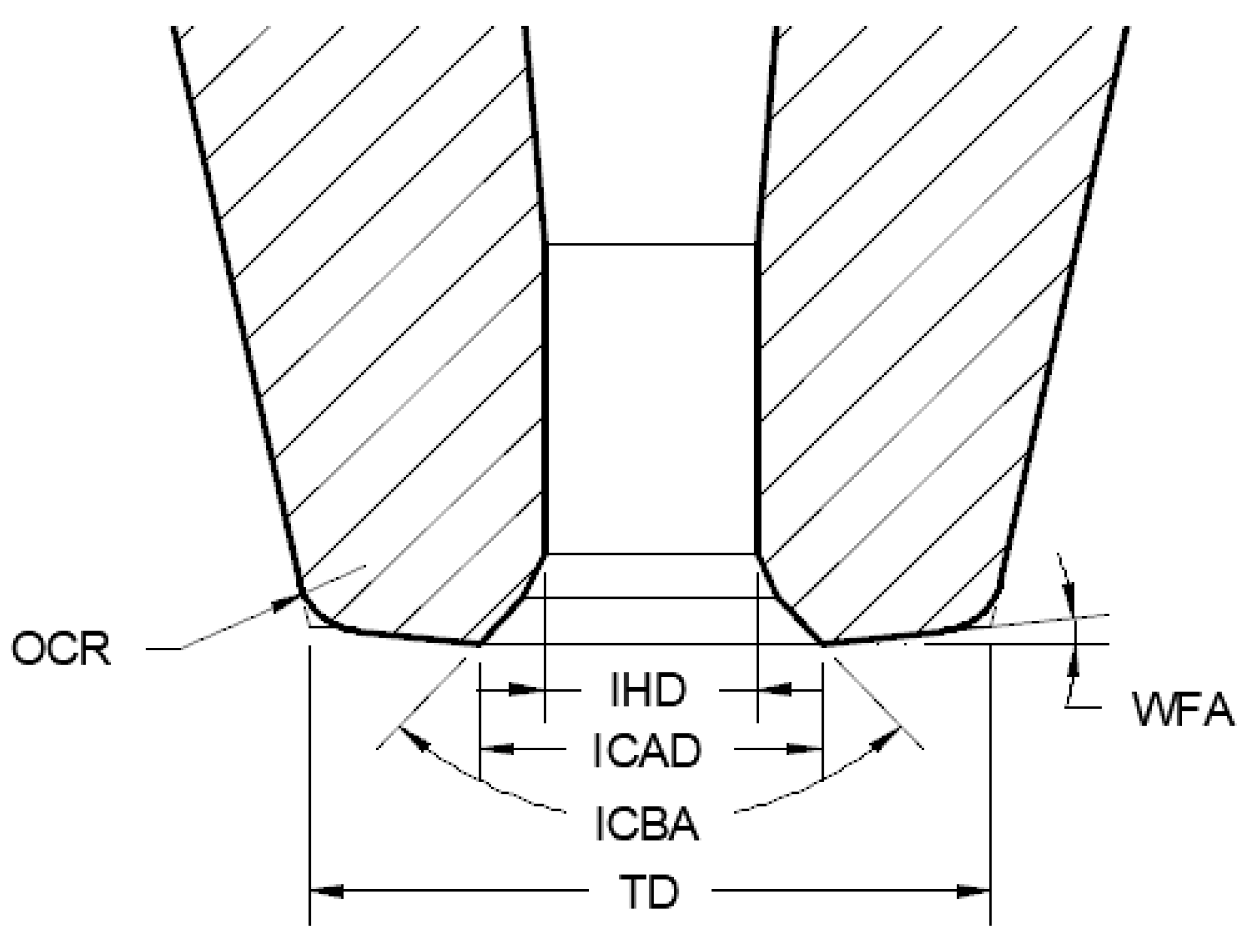
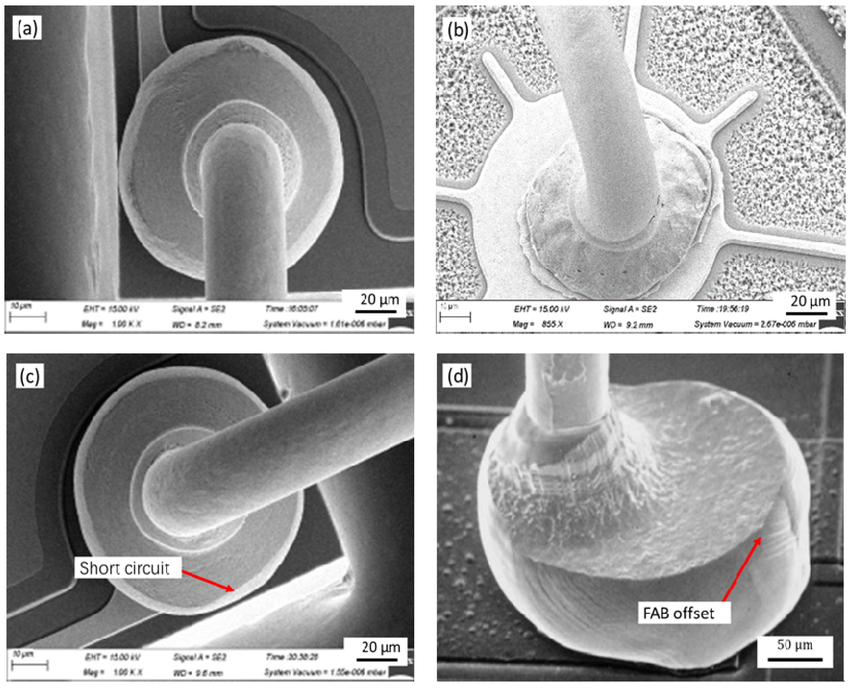
3.1. The Research on the Influence of IHD on the Morphology of Bonded Point
3.2. The Research on the Influence of the ICAD on the Morphology of the Bonded Point
3.3. Research on the Influence of ICBA on Bonded Point Morphology
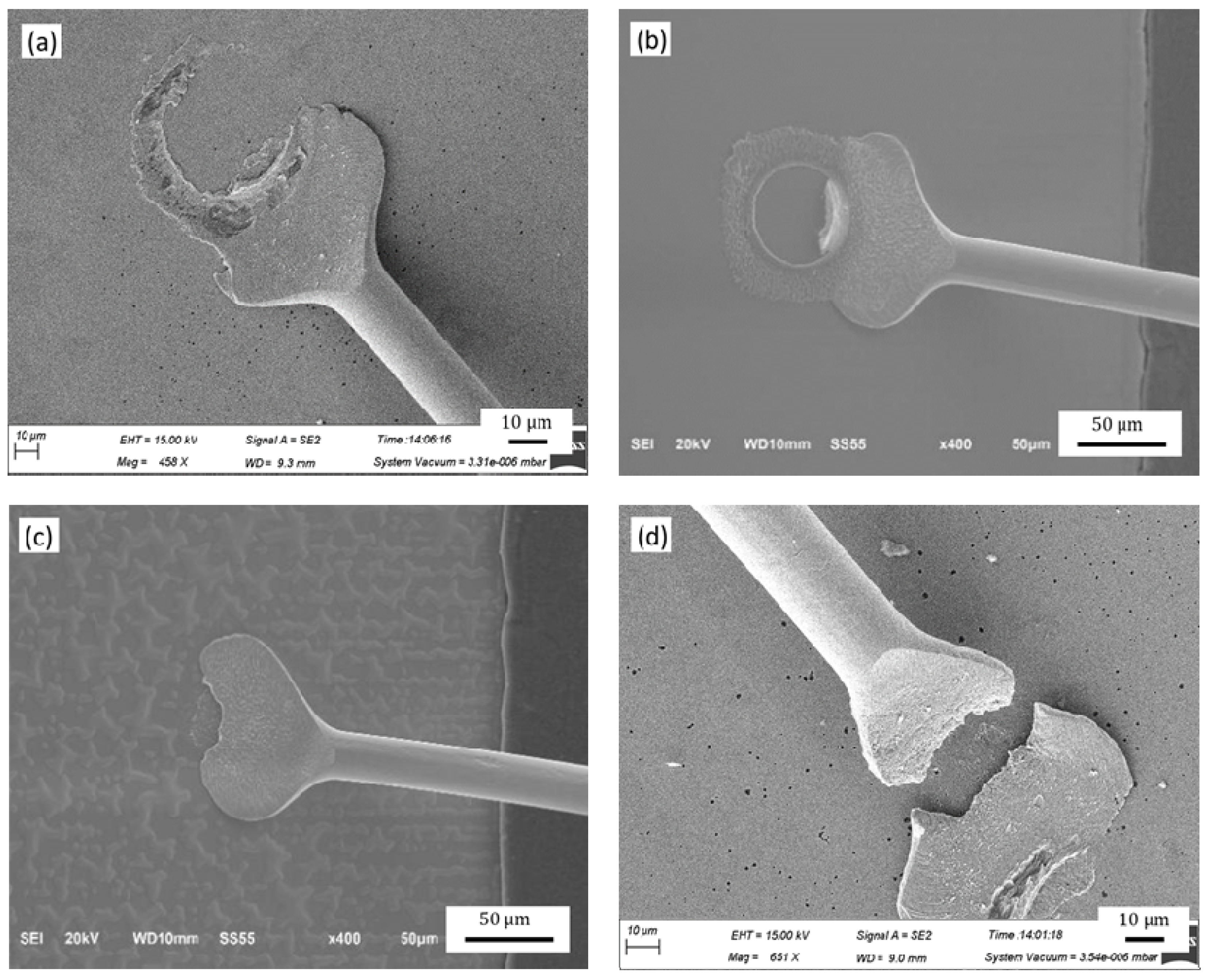
3.4. Research on the Influence of TD on Bonded Point Morphology
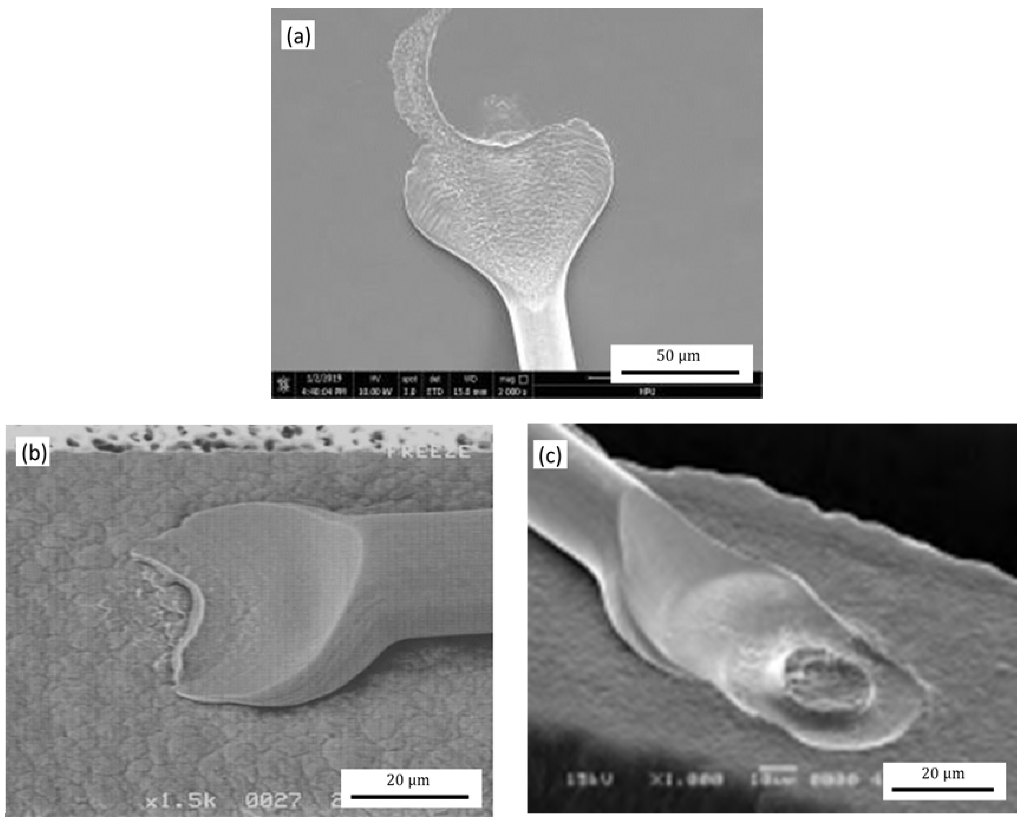
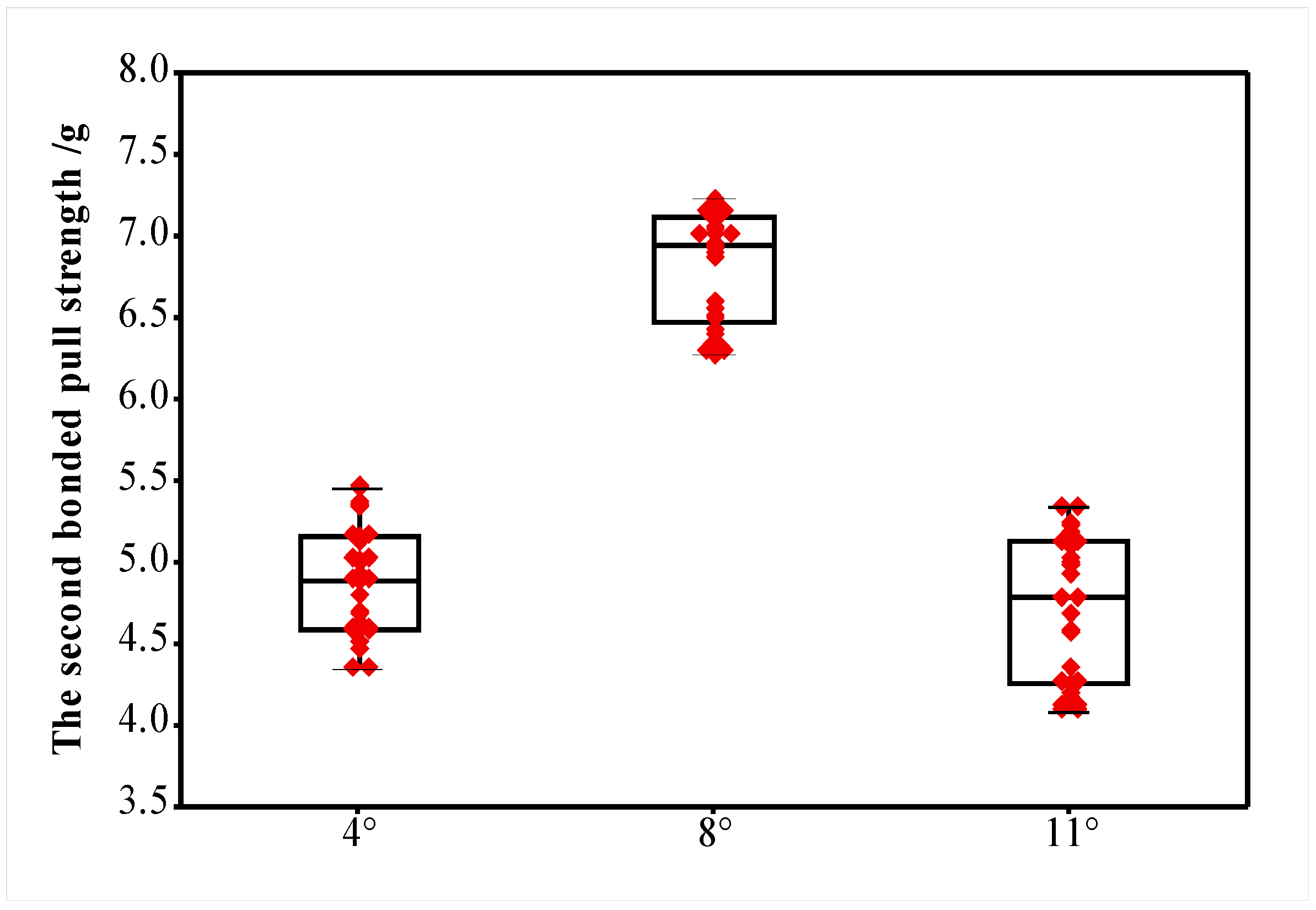
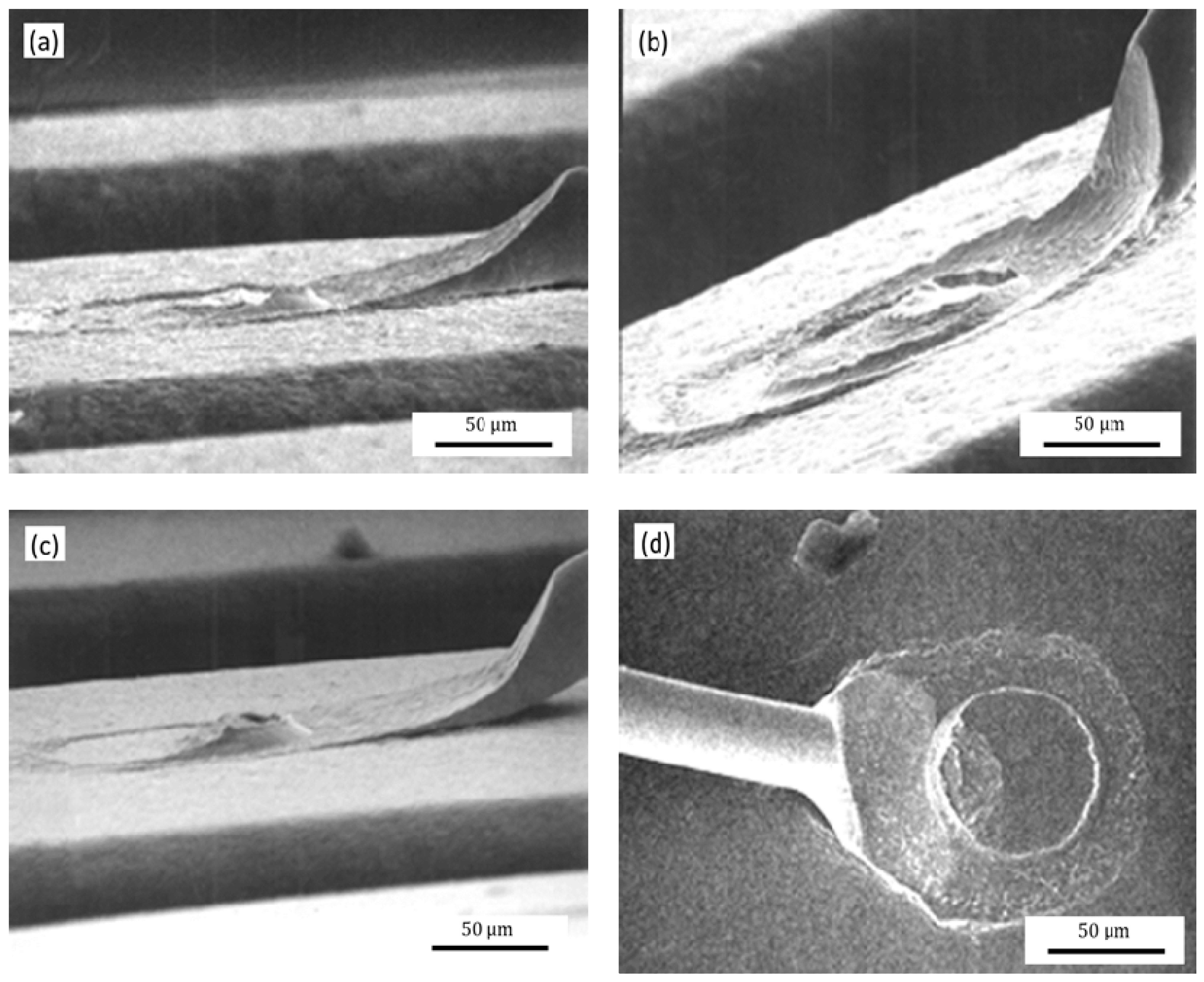
3.5. Research on the Influence of WFA on Bonded Point Morphology
3.6. Research on the Influence of OCR on Bonded Point Morphology
4. Conclusions
- (1)
- When the diameter of the inner hole of the ceramic capillary is 1.3 times (33 μm) of the diameter of the bonding alloy wire, the morphology of the MBD neck of the ball bonded point meets the requirements, and the increase or decrease of the IHD will cause the MBD neck of the ball bonded point irregular and reduced tensile strength.
- (2)
- When one of the ICAD or the ICBA of the ceramic capillary remains unchanged, the MBD size of the ball bonded point increases with the decrease of the ICAD or the increase of the ICBA. When the ICAD and ICBA is 64 μm and 100°, respectively. The size of the ball joint MBD meets the specifications.
- (3)
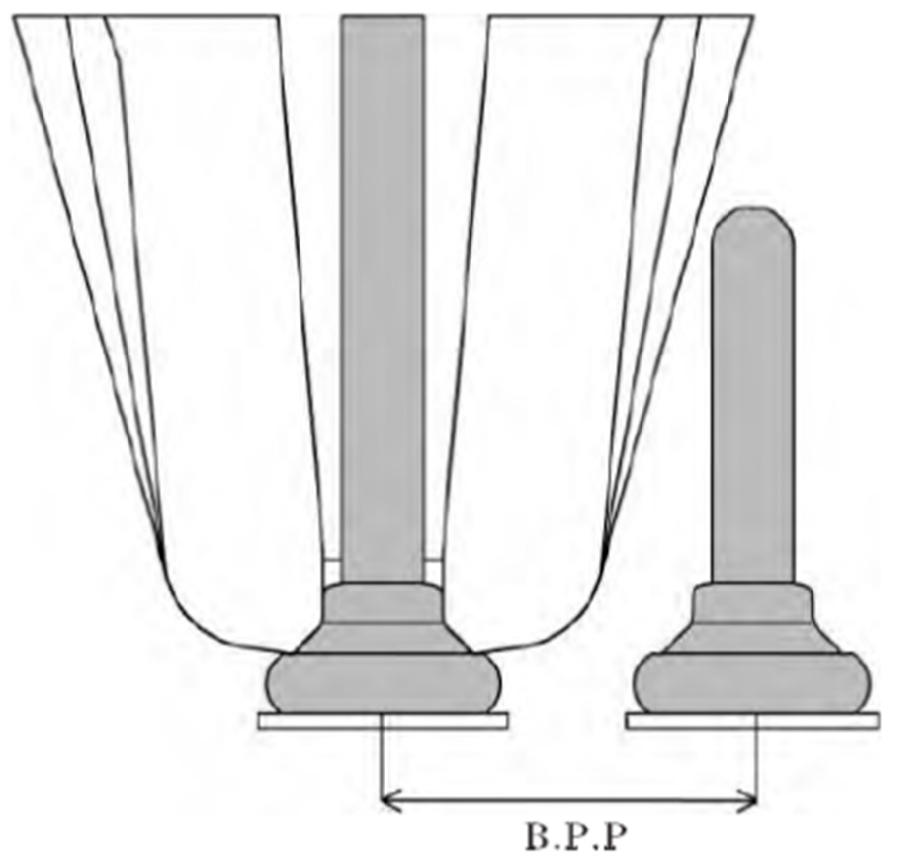
- The bonding strength and the contact area between the second bonded point and the pad increase with the increase of the TD of the capillary. However, the TD is too large to make the capillary contact the adjacent bonding wire, reducing the bonding accuracy. When the TD is 241 μm, the second bonded point has a good shape.
- (4)
- When one of the WFA and the OCR of the ceramic capillary remains unchanged, the fishtail shape of the second bonded point decreases with the increase of the WFA or the OCR. When the WFA and the OCR are respectively at 8° and 25.4 μm, the second bonded points are in a regular and symmetrical fishtail shape, and the power ring imprinting is complete.
Author Contributions
Funding
Data Availability Statement
Conflicts of Interest
References
- Ly, N.; Xu, D.E.; Song, W.H.; Mayer, M. More uniform Pd distribution in free air balls of Pd-coated Cu bonding wire using movable flame off electrode. Microelectron. Reliab. 2015, 55, 201. [Google Scholar] [CrossRef]
- Liu, P.S.; Tong, L.Y.; Wang, J.; Shi, L.; Tang, H. Challenges and developments of copper wire bonding technology. Microelectron. Reliab. 2012, 52, 1092. [Google Scholar] [CrossRef]
- Yu, X. China’s sealing and testing industry is rising. China’s Strateg. Emerg. Ind. 2017, 33, 56–57. [Google Scholar]
- Zhang, M. Overview of modern power electronics integration technology. High Power Convert. Technol. 2016, 1, 1–7. [Google Scholar]
- Wang, J. Development of electronic packaging and micro assembly sealing technology. Electron. Technol. 2011, 32, 197–201. [Google Scholar]
- Murali, S.; Srikanth, N.; Vath Charles, J. An Analysis of Intermetallics Formation of Gold and Copper Ball Bonding on the rmalAging. Mater. Res. Bull. 2003, 38, 637–646. [Google Scholar] [CrossRef]
- Hang, C.J.; Tian, Y.H.; Pelzer, R.; Zink, R.; Wöhlert, S.; Nelhiebel, M. High temperature storage reliability of Cu bonds by ultrasonicbonding with fine copper wire. Trans. China Weld. Inst. 2013, 34, 13–16. [Google Scholar]
- Tseng, Y.; Hung, F.; Lui, T.-S.; Chen, M.-Y.; Hsueh, H.-W. Effect of annealing on the microstructure and bonding interface properties of Ag–2Pd alloy wire. Microelectron. Reliab. 2015, 55, 1256–1261. [Google Scholar] [CrossRef]
- Guo, R.; Hang, T.; Mao, D.; Li, M.; Qian, K.; Lv, Z.L.; Chiu, H. Behavior of intermetallics formation and evolution in Ag-8Au-3Pd alloy wire bonds. J. Alloy. Compd. 2014, 588, 622–627. [Google Scholar] [CrossRef]
- Feng, D.; Taskinen, P. Thermodynamic properties of silver–palladium alloys determined by a solid state electrochemical method. J. Mater. Sci. 2014, 49, 5790–5798. [Google Scholar] [CrossRef]
- He, J.; Guo, Y.; Lin, Z. Effect of cleaver motion on interface deformation of thermo ultrasonic bonding. J. Shanghai Jiaotong Univ. 2008, 42, 716. [Google Scholar]
- Lu, L.; Han, L. Vibration characteristics of cleaver in ultrasonic bonding transducer system. Package Test Equip. 2008, 33, 1020. [Google Scholar]
- Yao, L. The influence of cleaver on gold wire bonding. Hybrid Microelectron. 2003, 9, 31. [Google Scholar]
- Goh, K.S.; Zhong, Z.W. Development of capillaries for wire bonding of low-kultra-fine-pitch devices. Microelectron. Eng. 2006, 83, 2009. [Google Scholar] [CrossRef]
- Kim, I.J.; Kim, H.S.; Seo, M.Y. Advanced ceramics in wire bonding capillaries for semiconductor package technology. Mater. Sci. Eng. 2008, 498, 129. [Google Scholar] [CrossRef]
- Cao, J.; Ding, Y.; Guo, T. Study on the influence of copper wire properties and bonding parameters on bonding quality. J. Mech. Eng. 2010, 46, 84–89. [Google Scholar] [CrossRef]
- Qin, W.; Gao, J.; Yang, Z.; Wu, X.; Li, K. Finite Element Analysis of Lead Bonding Process Parameters. Mech. Des. Manuf. 2011, 17–19. [Google Scholar]
- Xue, R. Effect of Ultrasonic Power and Bonding Pressure on the Bonding Quality of Gold Wire Thermal Ultrasonic Bonding; University of Electronic Science and Technology of China: Chengdu, China, 2016. [Google Scholar]
- Tian, Y.H.; Wang, C.Q.; Lum, I.; Mayer, M.; Jung, J.P.; Zhou, Y. Investigation of ultrasonic copper wire second bonding on Au/Ni plated Cu substrates at ambient temperature. Mater. Process. Technol. 2008, 208, 179. [Google Scholar] [CrossRef]
- Hou, T.; Su, C.H.; Chang, H.Z. Using neural networks and immune algorithms to find the optimal parameters for an lC wire bonding process. Expert Syst. Appl. 2008, 34, 427. [Google Scholar]
- Qiu, R. Study on the Influencing Factors of the First Bonded Point in Ultra-Fine Pitch Wire Bonding; Huazhong University of Science and Technology: Wuhan, China, 2004. [Google Scholar]
- Pequegnat, A. Effect of gas type and flow rate on Cu free air ball formation in thermosonic wire bonding. Microelectron. Reliab. 2011, 51, 43–52. [Google Scholar] [CrossRef]
- Yang, Z. Research on Image Recognition System of Intelligent IC Wire Bonder; Guangdong University of Technology: Guangzhou, China, 2005. [Google Scholar]
- Dong, Y. Development and process research of thermoacoustic welding machine. Electron. Process. Technol. 2004, 25, 84–85. [Google Scholar]
- Li, Y. Technical analysis of wire bonder. Spec. Equip. Electron. Ind. 2004, 33, 78–81. [Google Scholar]
- Qiu, Y. Microjunctions in microwave multichip modules. Electron. Technol. 2005, 26, 319–322. [Google Scholar]
- Huang, Y. Lead bonding technology in integrated circuit packaging. Electron. Packag. 2006, 6, 16–20. [Google Scholar]
- Lu, K.; Wang, C.; Tian, Y. Study on the ultrasonic bonding FAB process and its influence of Cu lead. Electron. Technol. 2008, 29, 192–207. [Google Scholar]
- Cao, J.; Ding, Y.; Cao, W. Research on wire breakage during the preparation of single crystal copper bonding wire. Acta Mech. Eng. 2010, 46, 84–89. [Google Scholar] [CrossRef]
- Fan, H.; Ma, X.; Liu, X. Preparation of bonded silver wire. Gold 2017, 38, 6–9. [Google Scholar]
- Cao, J.; Fan, J.; Gao, W. Effect of cold deformation and heat treatment on linear energy of Ag-4Pd bonded alloy. Acta Mech. Eng. 2016, 18, 92–97. [Google Scholar] [CrossRef]
- Zhu, J. Research trends in alloying of bonded gold wires. Precious Met. 2002, 23, 57–61. [Google Scholar]
- Guo, Y.; Yang, G.; Kong, J.; DAO, P.; Huan, W.; Guan, W. Development and application of gold bonding wires. Precious Met. 2009, 30, 68–71. [Google Scholar]
- Gong, Z.; Wang, X.; Wang, L. Progress in research and application of ceramic cleavers in microelectronics. Mater. Guide 2015, 29, 90–91. [Google Scholar]
- Lando, D.J.; Mitchell, J.P.; Welsher, T.L. Conductive anodic filaments in reinforced Polymeric dielectrics: Formation and prevention. In Proceedings of the 17th Ebrahimi Annual, Reliability Physics Symposium, San Diego, CA, USA, 24–26 April 1979; pp. 39–43. [Google Scholar]
- Lahti, J.N.; Delaney, R.H.; Hines, J.N. The characteristic wearout process in epoxy-glass printed circuits for high density electronic packaging. In Proceedings of the 17th Annual Reliability Physics Symposium, San Diego, CA, USA, 24–26 April 1979; pp. 39–43. [Google Scholar]


| Ag Content (%) | Au Content (%) | Strength (N) | Elongation (%) | |
|---|---|---|---|---|
| Ag-5Au | 95 | 5 | 0.095 | 14.1 |
| Items | IHD (μm) | ICAD (μm) | ICBA (°) | TD (μm) | WFA (°) | OCR (μm) |
|---|---|---|---|---|---|---|
| 1 | 33 | 64 | 100 | 178 | 8 | 25.4 |
| 2 | 26 | 64 | 100 | 178 | 8 | 25.4 |
| 3 | 41 | 64 | 100 | 178 | 8 | 25.4 |
| 4 | 33 | 51 | 100 | 178 | 8 | 25.4 |
| 5 | 33 | 76 | 100 | 178 | 8 | 25.4 |
| 6 | 33 | 64 | 70 | 178 | 8 | 25.4 |
| 7 | 33 | 64 | 120 | 178 | 8 | 25.4 |
| 8 | 33 | 64 | 100 | 127 | 8 | 25.4 |
| 9 | 33 | 64 | 100 | 241 | 8 | 25.4 |
| 10 | 33 | 64 | 100 | 178 | 4 | 25.4 |
| 11 | 33 | 64 | 100 | 178 | 11 | 25.4 |
| 12 | 33 | 64 | 100 | 178 | 8 | 20.0 |
| 13 | 33 | 64 | 100 | 178 | 8 | 30.0 |
Publisher’s Note: MDPI stays neutral with regard to jurisdictional claims in published maps and institutional affiliations. |
© 2020 by the authors. Licensee MDPI, Basel, Switzerland. This article is an open access article distributed under the terms and conditions of the Creative Commons Attribution (CC BY) license (http://creativecommons.org/licenses/by/4.0/).
Share and Cite
Cao, J.; Zhang, J.; Song, K.; Wu, B.; Ding, Y.; Chen, D.; Ding, Y. Effect of Ceramic Capillary Parameters on Bonded Morphology and Strength. Micromachines 2021, 12, 24. https://doi.org/10.3390/mi12010024
Cao J, Zhang J, Song K, Wu B, Ding Y, Chen D, Ding Y. Effect of Ceramic Capillary Parameters on Bonded Morphology and Strength. Micromachines. 2021; 12(1):24. https://doi.org/10.3390/mi12010024
Chicago/Turabian StyleCao, Jun, Junchao Zhang, Kexing Song, Baoan Wu, Yong Ding, Dingbiao Chen, and Yutian Ding. 2021. "Effect of Ceramic Capillary Parameters on Bonded Morphology and Strength" Micromachines 12, no. 1: 24. https://doi.org/10.3390/mi12010024
APA StyleCao, J., Zhang, J., Song, K., Wu, B., Ding, Y., Chen, D., & Ding, Y. (2021). Effect of Ceramic Capillary Parameters on Bonded Morphology and Strength. Micromachines, 12(1), 24. https://doi.org/10.3390/mi12010024