Modification of Higher Alkanes by Nanoparticles to Control Light Propagation in Tapered Fibers


Abstract
1. Introduction
2. Materials and Methods
2.1. Materials
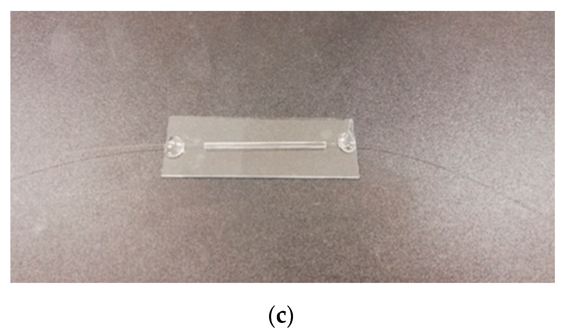
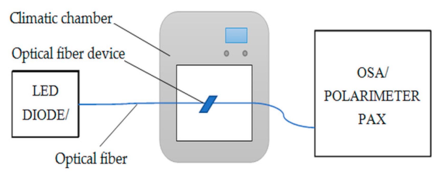
2.2. Technology
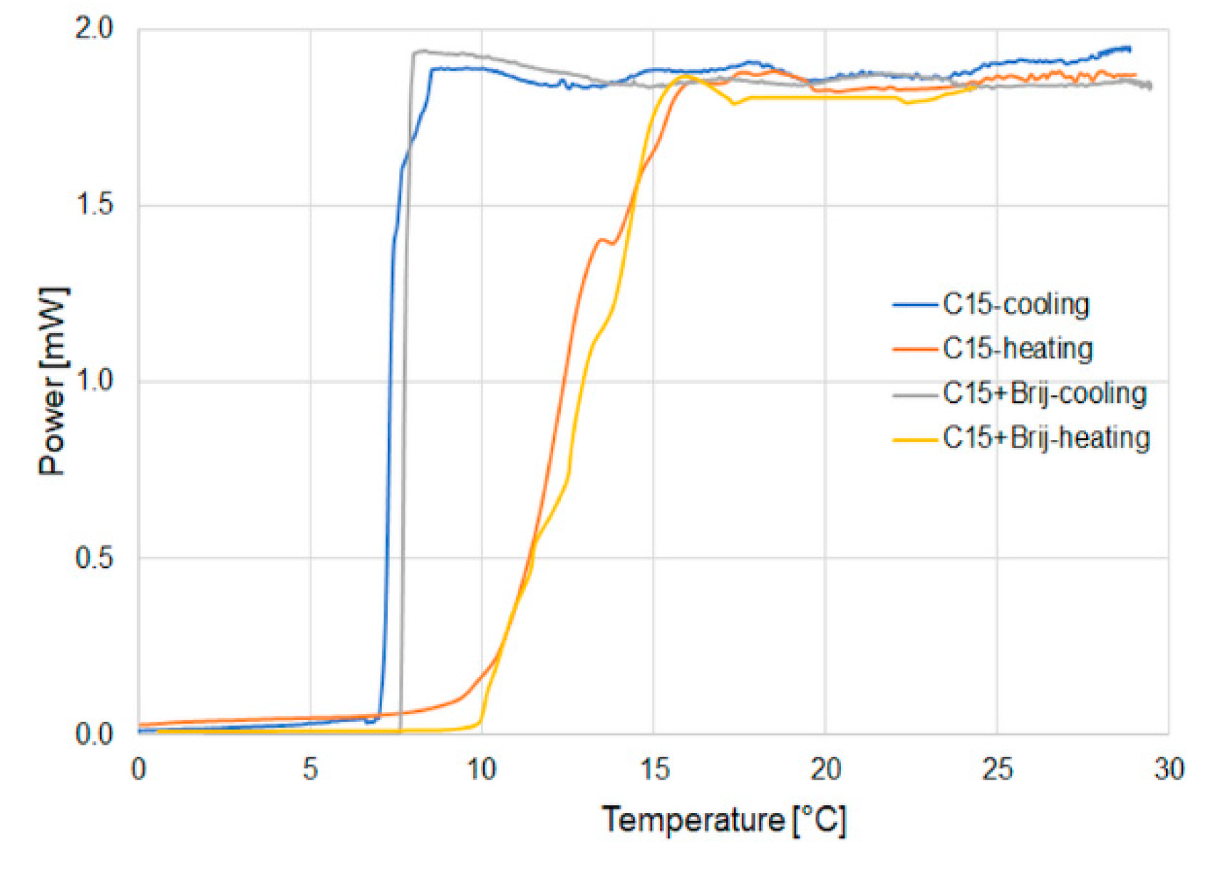
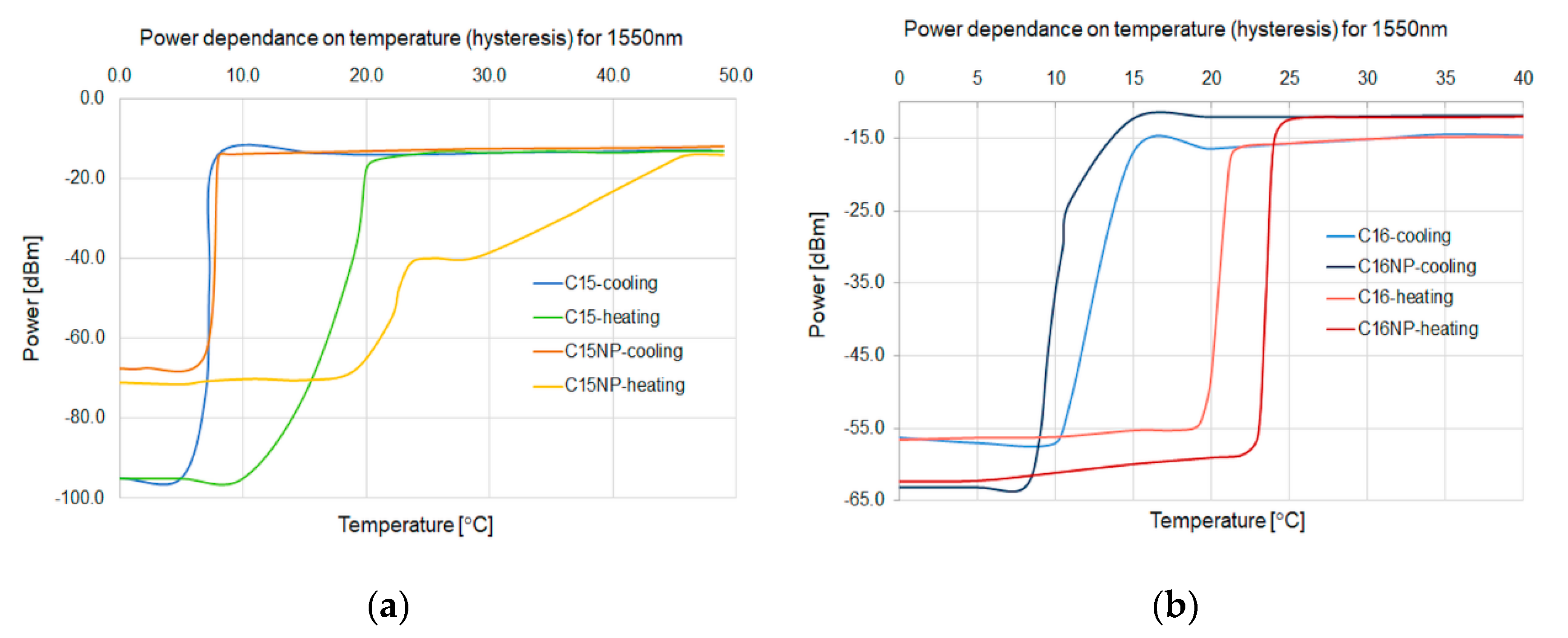
3. Results and Discussion
4. Conclusions
Author Contributions
Funding
Acknowledgments
Conflicts of Interest
References
- Katsunari, O. Wave Theory of Optical Waveguides. In Fundamentals of Optical Waveguides, 2nd ed.; Academic Press: London, UK, 2006; Volume 3, pp. 32–47. [Google Scholar]
- Born, M.; Wolf, E. Principles of Optics; Cambridge University Press: Cambridge, UK, 2003. [Google Scholar]
- Tsao, C. Optical Fiber Waveguide Analysis; Oxford University Press: London, UK, 1992. [Google Scholar]
- Russell, P.J. Photonic crystal fibers. Science 2003, 299, 358–362. [Google Scholar] [CrossRef] [PubMed]
- Paschotta, R. Field Guide to Optical Fiber Technology; SPIE Press: Bellingham, WA, USA, 2010. [Google Scholar]
- Rajan, G. Optical Fiber Sensors: Advanced Techniques and Applications. In Optical Fiber Sensors: Advanced Techniques and Applications; CRC Press: London, UK, 2015; pp. 413–425. [Google Scholar]
- Tian, Y.; Wang, W.; Wu, N.; Zou, X.; Wang, X. Tapered Optical Fiber Sensor for Label-Free Detection of Biomolecules. Sensors 2011, 11, 3780–3790. [Google Scholar] [CrossRef] [PubMed]
- Villatoro, J.; Monzon-Hernandez, D.; Mejıa, E. Fabrication and modeling of uniform-waist single-mode tapered optical fiber sensors. Appl. Opt. 2003, 42, 2278–2283. [Google Scholar] [CrossRef] [PubMed]
- Paul, P.H.; Kychakoff, G. Fiber-optic evanescent field absorption sensor. Appl. Phys. Lett. 1987, 51, 12–14. [Google Scholar] [CrossRef]
- Moar, P.N. Fabrication, modeling, and direct evanescent field measurement of tapered optical fiber sensors. J. Appl. Phys. 1999, 85, 3395–3398. [Google Scholar] [CrossRef]
- Stasiewicz, K.; Moś, J. Influence of a thin metal layer on a beam propagation in a biconical optical fibre taper. Opto-Electron. Rev. 2016, 24, 196–208. [Google Scholar] [CrossRef]
- Kaminow, I. Optical Fiber Telecommunication; Academic Press: Cambridge, MA, USA, 2008. [Google Scholar]
- Lee, B.H.; Kim, J.H.; Park, K.S.; Eom, J.B.; Kim, M.J.; Rho, B.S.; Choi, H.Y. Interferometric Fiber Optic Sensor. Sensors 2012, 12, 2467–2480. [Google Scholar] [CrossRef]
- Fang, Z. Fundamentals of Optical Fiber Sensors; Wiley: Hoboken, NJ, USA, 2012. [Google Scholar]
- Talapin, D.V.; Lee, J.S.; Kovalenko, M.V.; Shevchenko, E.V. Prospects of Colloidal Nanocrystals for Electronic and Optoelectronic Applications. Chem. Rev. 2010, 110, 389–458. [Google Scholar] [CrossRef]
- Matras-Postolek, K.; Bogdal, D. Polymer Nanocomposites for Electro-Optics: Perspectives on Processing Technologies, Material Characterization, and Future Application. Adv. Polym. Sci. 2010, 230, 221–282. [Google Scholar]
- Matras-Postolek, K.; Sovinska, S.; Żaba, A.; Yang, P. Microwave-assisted heating versus conventional heating in solvothermal and non-solvothermal synthesis of photocatalytic active ZnSe·0.5N2H4 and ZnSe:Mn·0.5N2H4 anisotropic colloidal quasi-two-dimensional hybrid nanoplates. Chem. Eng. Process. 2017, 122, 346–356. [Google Scholar] [CrossRef]
- Matras-Postołek, K.; Sovinska, S.; Węgrzynowicz, A. Synthesis and characterization of ZnSe and ZnSe:Mn nanosheets and microflowers with high photoactive properties by microwave-assisted method. Chem. Eng. Process. 2019, 135, 204–216. [Google Scholar] [CrossRef]
- Liu, Y.; Yang, P.; Li, J.; Matras-Postolek, K.; Yue, Y.; Huang, B. Formation of SiO2@SnO2 core–shell nanofibers and their gas sensing properties. RSC Adv. 2016, 6, 13371–13376. [Google Scholar] [CrossRef]
- Bredola, M.; Matras, K.; Szatkowski, A.; Sanetra, J.; Prodi-Schwab, A. P3HT/ZnS: A new hybrid bulk heterojunction photovoltaic system with very high open circuit voltage. Sol. Energy Mater. Sol. Cells 2009, 93, 662–666. [Google Scholar] [CrossRef]
- Matras-Postołek, K.; Żaba, A.; Nowak, E.M.; Dąbczyński, P.; Rysz, J.; Sanetra, J. Formation and characterization of one-dimensional ZnS nanowires for ZnS/P3HT hybrid polymer solar cells with improved efficiency. Appl. Surf. Sci. 2018, 451, 180–190. [Google Scholar] [CrossRef]
- Matras, K.; Bredol, M.; Sakhnov, O.; Stumpe, J.; Bogdal, D.; Szatkowski, A. Composites from luminescent nanosized ZnS and optical polimer. Mol. Cryst. Liq. Cryst. 2008, 485, 776–779. [Google Scholar] [CrossRef]
- Martínez-Castañóna, G.A.; Martínez-Mendoza, J.R.; Ruiz, F.; González-Hernández, J. Synthesis and optical characterization of ZnS, ZnS:Mn and (ZnS:Mn)_CdS core-shell nanoparticles. Inorg. Chem. Commun. 2007, 5, 531–534. [Google Scholar]
- Sharma, R.; Bisen, D.P. Thermoluminescence of mercaptoethanol-capped ZnS:Mn nanoparticles. Luminescence 2015, 30, 175–181. [Google Scholar] [CrossRef]
- Tong, L.; Sumetsky, M.I. Subwavelength and Nanometer Diameter Optical Fibers; Springer: Berlin, Germany, 2011; pp. 1–22. [Google Scholar]
- Moayyed, H.; Teixeira Leite, I.; Coelho, L.; Santos, J.; Viegas, D. Analysis of Phase Interrogated SPR Fiber Optic Sensors with Biometallic Layers. IEEE Sens. J. 2014, 14, 3662–3668. [Google Scholar] [CrossRef]
- Prodi-Schwab, A.; Adam, D.; Lüthge, T.; Bredol, M.; Matras, K.; Szatkowski, A. Lumineszente nanoskalige Partikel mit hydrophober Oberflächenausstattung, Verfahren zu ihrer Herstellung sowie ihre Verwendung. Germany Patent No. WO2009133138A1, 5 November 2009. [Google Scholar]
- Bumb, A.; Sarkar, S.K.; Neuman, K.C.; Brechbiel, M. Method of Preparing Silica-Coated Nanodiamonds. U.S. Patent No. US 2015/0190843 A1, 9 July 2015. [Google Scholar]
- Sabri, N.; Aljunid, S.A.; Salim, M.S.; Ahmad, R.B.; Kamaruddin, R. Toward Optical Sensors: Review and Applications. J. Phys. Conf. Ser. 2013, 423, 2064–2072. [Google Scholar] [CrossRef]
- Chen, L.; Chan, C.; Ni, K.; Hu, P.; Li, K.; Wong, W.; Leong, K. Label-free fiber-optic interferometric immunosensors based on waist-enlarged fusion taper. Sensor Actuat. B-Chem. 2013, 178, 176–184. [Google Scholar] [CrossRef]
- Arregui, F.J.; Matías, I.R.; López-Amo, M. Optical fiber strain gauge based on a tapered single-mode fiber. Sensor Actuat. A 2000, 79, 90–96. [Google Scholar] [CrossRef]
- Kieu, K.Q.; Mansuripur, M. Biconical fiber taper sensors. IEEE Photonics Technol. Lett. 2006, 18, 2239–2241. [Google Scholar] [CrossRef]
- Latifi, H.; Zibaii, M.I.; Hosseini, S.M.; Jorge, P. Nonadiabatic tapered optical fiber for biosensor applications. Photonic Sens. 2012, 2, 340–356. [Google Scholar] [CrossRef]
- Stasiewicz, K.A.; Musiał, J.E. Threshold temperature optical fibre sensors. Opt. Fiber Technol. 2016, 32, 111–118. [Google Scholar] [CrossRef]
- Vélez, C.; de Zárate, J.M.O.; Khayet, M. Thermal properties of n-pentadecane, n-heptadecane and n-nonadecane in the solid/liquid phase change region. Int. J. Therm. Sci. 2015, 94, 139–146. [Google Scholar] [CrossRef]
- Vélez, C.; Khayet, M.; de Zárate, J.M.O. Temperature-dependent thermal properties of solid/liquid phase change even-numbered n-alkanes: N-Hexadecane, n-octadecane and n-eicosane. Appl. Energ. 2015, 143, 383–394. [Google Scholar] [CrossRef]
- Oćwieja, M.; Matras-Postołek, K.; Maciejewska-Prończuka, J.; Morga, M.; Adamczyk, Z.; Sovinska, S.; Żaba, A.; Gajewska, M.; Król, T.; Cupiał, K.; et al. Formation and stability of manganese-doped ZnS quantum dot monolayers determined by QCM-D and streaming potential measurements. J. Colloid Interf. Sci. 2017, 503, 186–197. [Google Scholar] [CrossRef]
- Murugadoss, G.; Rajamannan, B.; Ramasamy, V. Synthesis, characterization and optical properties of water-soluble ZnS:Mn2+ nanoparticles. J. Lumin. 2010, 130, 2032–2039. [Google Scholar] [CrossRef]
- Ma, X.; Song, J.; Yu, Z. The light emission properties of ZnS:Mn nanoparticles. Thin Solid Films 2011, 519, 5043–5045. [Google Scholar] [CrossRef]
- Popovetskiy, P.S. Synthesis and Characterization of Silver Nanoparticles in Reverse Micelles of Nonionic Surfactants and in Their Mixed Micelles with AOT. Colloid J. 2020, 82, 144–151. [Google Scholar] [CrossRef]
- Marc, P.; Przybysz, N.; Molska, A.; Jaroszewicz, L.R. Photonic Crystal Fiber Transducers for an Optical Fiber Multilevel Temperature Threshold Sensor. J. Lightwave Technol. 2017, 36, 898–903. [Google Scholar] [CrossRef]
- Freund, M.; Csikos, R.; Keszthelyi, S.; Mozes, G.Y. Paraffin Products: Properties Technologies, Applications; Elsevier Scientific Publishing Company: New York, NY, USA, 1982; pp. 90–123. [Google Scholar]


| Parameter [Units] | Core | Cladding | Mode Field |
|---|---|---|---|
| Diameter [µm] | 8.2 | 125 | 10.98 |
| Refractive index [a.u.] | 1.4548 | 1.443 | -- |
| Alkane | Formula | Molecular Mass | Melting Point | Boiling Point | Flash Point | Density | Refractive Index | Refractive Index at 20.4 °C |
|---|---|---|---|---|---|---|---|---|
| n-Pentadecane | CH3(CH2)13CH3 | 212.42 | 9–10 °C | 269–270 °C | 132 °C (269 °F) | 0.769 | 1.4320 | 1.4317 |
| n-Hexadecane | CH3(CH2)14CH3 | 226.45 | 18 °C | 287 °C | 135 °C (275 °F) | 0.773 | 1.4345 | 1.4344 |
| Formula | Molecular Mass | Melting Point | Solubility |
|---|---|---|---|
| C58H118O24 | 1199.57 | ~56–60 °C | At 20 °C in methanol, chloroform and ethanol |
| C15 | C15 with Brij | C15 with Brij and Nanoparticles | C16 | C16 with Brij | C16 with Brij and Nanoparticles |
|---|---|---|---|---|---|
| 1.4317 | 1.4319 | 1.4319 | 1.4344 | 1.4346 | 1.4346 |
Publisher’s Note: MDPI stays neutral with regard to jurisdictional claims in published maps and institutional affiliations. |
© 2020 by the authors. Licensee MDPI, Basel, Switzerland. This article is an open access article distributed under the terms and conditions of the Creative Commons Attribution (CC BY) license (http://creativecommons.org/licenses/by/4.0/).
Share and Cite
Stasiewicz, K.A.; Jakubowska, I.; Korec, J.; Matras-Postołek, K. Modification of Higher Alkanes by Nanoparticles to Control Light Propagation in Tapered Fibers. Micromachines 2020, 11, 1006. https://doi.org/10.3390/mi11111006
Stasiewicz KA, Jakubowska I, Korec J, Matras-Postołek K. Modification of Higher Alkanes by Nanoparticles to Control Light Propagation in Tapered Fibers. Micromachines. 2020; 11(11):1006. https://doi.org/10.3390/mi11111006
Chicago/Turabian StyleStasiewicz, Karol A., Iwona Jakubowska, Joanna Korec, and Katarzyna Matras-Postołek. 2020. "Modification of Higher Alkanes by Nanoparticles to Control Light Propagation in Tapered Fibers" Micromachines 11, no. 11: 1006. https://doi.org/10.3390/mi11111006
APA StyleStasiewicz, K. A., Jakubowska, I., Korec, J., & Matras-Postołek, K. (2020). Modification of Higher Alkanes by Nanoparticles to Control Light Propagation in Tapered Fibers. Micromachines, 11(11), 1006. https://doi.org/10.3390/mi11111006