Article

Arctic Sea Ice Thickness Estimation from CryoSat-2 Satellite Data Using Machine Learning-Based Lead Detection

1
School of Urban and Environmental Engineering, Ulsan National Institute of Science and Technology, Ulsan 44919, Korea
2
Space Imaging R&D Lab, LIG Nex1 Co., Ltd., Yongin 16911, Korea
3
Division of Polar Ocean Environment, Korea Polar Research Institute, Incheon 21990, Korea
4
Department of Environmental Resources Engineering, State University of New York, College of Environmental Science and Forestry, Syracuse, NY 13210, USA
1
University College London, London, UK
*
Author to whom correspondence should be addressed.
Remote Sens. 2016, 8(9), 698; https://doi.org/10.3390/rs8090698
Submission received: 30 April 2016 / Revised: 14 August 2016 / Accepted: 19 August 2016 / Published: 24 August 2016
(This article belongs to the Special Issue Sea Ice Remote Sensing and Analysis)

Abstract

:
Satellite altimeters have been used to monitor Arctic sea ice thickness since the early 2000s. In order to estimate sea ice thickness from satellite altimeter data, leads (i.e., cracks between ice floes) should first be identified for the calculation of sea ice freeboard. In this study, we proposed novel approaches for lead detection using two machine learning algorithms: decision trees and random forest. CryoSat-2 satellite data collected in March and April of 2011–2014 over the Arctic region were used to extract waveform parameters that show the characteristics of leads, ice floes and ocean, including stack standard deviation, stack skewness, stack kurtosis, pulse peakiness and backscatter sigma-0. The parameters were used to identify leads in the machine learning models. Results show that the proposed approaches, with overall accuracy >90%, produced much better performance than existing lead detection methods based on simple thresholding approaches. Sea ice thickness estimated based on the machine learning-detected leads was compared to the averaged Airborne Electromagnetic (AEM)-bird data collected over two days during the CryoSat Validation experiment (CryoVex) field campaign in April 2011. This comparison showed that the proposed machine learning methods had better performance (up to r = 0.83 and Root Mean Square Error (RMSE) = 0.29 m) compared to thickness estimation based on existing lead detection methods (RMSE = 0.86–0.93 m). Sea ice thickness based on the machine learning approaches showed a consistent decline from 2011–2013 and rebounded in 2014.

Graphical Abstract

1. Introduction

Sea ice impacts the Earth’s radiation balance because thermal feedback between the Sun and the Earth is highly sensitive to sea ice reflectivity. Thus, Arctic sea ice is considered an important factor in understanding the global climate change process [1]. The reflectivity of sea ice strongly depends on the spatial distribution and extent of the ice [2,3], which have rapidly changed due to global warming over the past two decades [4,5]. Boe et al. [6] used various climate model simulations to predict that the Arctic Ocean would probably be ice-free by the end of the 21st century. Furthermore, several studies have shown that the decline of sea ice is occurring faster than model predictions [7,8]. Thus, there is an increasing need for accurate monitoring of sea ice concentration and thickness to better understand polar and global climate systems and processes.
Sea ice thickness has been measured with various methods. While direct field measurements of sea ice thickness using a submarine upward looking sonar [9,10] or an electromagnetic system (e.g., Airborne Electromagnetic (AEM)-31) [11,12,13] can provide accurate ice thickness information, such techniques can only be applied to local areas within a very limited time frame. Observation of sea ice thickness over vast areas has utilized various space-borne radar and laser altimeter sensors [14,15,16,17,18,19,20]. Laxon et al. [14] retrieved sea ice thickness using European Remote Sensing Satellite-1 (ERS-1) and ERS-2 satellite data based on radar altimetry. Kwok et al. [15] also estimated sea ice thickness using Ice, Cloud and land Elevation Satellite (ICESat) data based on laser altimetry. Unfortunately, the operation of ICESat stopped in 2009 due to the failure of its main instrument. Since the launch of CryoSat-2 in 2010, researchers have developed various methods to use the radar altimetry observations to estimate sea ice thickness from CryoSat-2 data [16,17,18,19].
Sea ice thickness can be estimated from sea ice freeboard based on isostasy [21]. Derivation of sea ice freeboard is an important procedure for estimating the ice thickness by laser or radar altimeter measurements. In particular, identification of leads (i.e., fractures between sea ice floes) is crucial to estimate the freeboard. The height of leads extracted by such measurements enables the calculation of the Local Sea Surface Height (LSSH), and then, freeboard can be estimated using LSSH, actual sea surface height and the surface elevation of the ice extracted by altimetric measurements. Kwok et al. [15] detected leads through direct comparison between the surface elevation profiles extracted by ICESat data and near-coincident Synthetic Aperture Radar (SAR) images. Zwally et al. [22] assumed that the lowest 2% values of the surface elevation profiles from ICESat would correspond to leads. In addition to these relatively simple methods, Farrell et al. [23] proposed a threshold-based method to distinguish leads from ice floes using various parameters extracted from ICESat level 1b data, such as gain, reflectivity, radiance and waveform characteristics. In the case of CryoSat-2, Pulse Peakiness (PP) and Stack Standard Deviation (SSD) parameters are frequently used for lead detection. For example, Ricker et al. [19] used various waveform parameters, such as PP, SSD, stack kurtosis and sea ice concentration, to distinguish leads from ice floes. Although these lead detection methods have been developed in several studies, the determination of ice thickness from CryoSat-2 still suffers from a lack of precise lead discrimination [24]. Simple thresholding methods might not perfectly distinguish leads from ice floes because parameters, such as PP, SSD, stack skewness, stack kurtosis and backscatter sigma-0 (Section 2.1) typically contain aliasing between leads and ice floes, which can result in large errors and uncertainties in sea ice thickness estimates. Therefore, advanced techniques to optimize such thresholds and minimize the associated errors are needed. This study proposes decision trees and random forest machine learning approaches to identify leads and ice floes from CryoSat-2 and Moderate Resolution Imaging Spectroradiometer (MODIS) in order to estimate sea ice thickness.

2. Observational Datasets

Freeboard height and ice thickness for March and April in 2011–2014 were calculated from CryoSat-2 data based on machine learning-based lead detection approaches. MODIS and sea ice type data were used as ancillary data when estimating sea ice thickness. The estimated ice thickness was validated using CryoSat Validation experiment (CryoVex) field campaign data (i.e., airborne electromagnetics data) over northwestern Greenland acquired in April 2011.

2.1. CryoSat-2

CryoSat-2 was launched in April 2010 and carries the space-borne Synthetic Aperture Interferometric Radar Altimeter (SIRAL) developed by the European Space Agency (ESA) [25]. SIRAL has a center frequency of 13.575 GHz (Ku-band) and a bandwidth of 320 MHz. It has three operation modes: Low Resolution Mode (LRM), Synthetic Aperture Radar (SAR) and SAR Interferometry (SIN). ESA explains that data collected in SAR and SIN modes are optimized to estimate sea ice thickness because the sensor in the operation modes can measure sea ice characteristics with high spatial resolution comparable to the size of leads [26]. In the CryoSat-2 waveform data, the power of the received microwave signal is recorded in 128 range bins in SAR mode and 512 range bins in SIN mode. The interval of each range bin is almost 1.563 ns (~0.234 m). Detailed specifications of CryoSat-2 are presented in Table 1.
CryoSat-2 (Baseline B) and CryoSat-2 Level 1B (L1B) waveform data were used to estimate surface elevation (ftp://science-pds.cryosat.esa.int). Five parameters (i.e., SSD, stack skewness, stack kurtosis, PP and backscatter sigma-0) were used to distinguish leads from ice floes and ocean, as they can represent surface characteristics, such as surface roughness and dielectric property. SSD was available from L1B data; stack skewness and stack kurtosis were available from Level 2I (L2I) data, which are provided by ESA. SSD is the variation of the stacked power distribution with an incidence angle [26]. Stack skewness and stack kurtosis measure the asymmetry and peakedness of the range stacked power distribution, respectively [25]. PP is commonly used to identify leads and ice floes [16,18,19,27]. The equations to calculate SSD, stack skewness and kurtosis, as well as PP are summarized in Table 2.
The radar backscatter sigma-0 (i.e., backscatter coefficient) from Level 2 (L2) data, documenting the observed surface, is a function of dielectric properties, the radar frequency, incidence angle, the target surface roughness, geometric shape and volume scattering [25]. The SAR L1b waveforms can be converted into watts using power scaling parameters that are available in the L1b product. The radar equation is solved using transmit power, range and instrument gain and bias correction to retrieve backscatter sigma-0. A bias correction value is then applied to remove any residual bias [30]. Since these parameters are sensitive to change in surface condition, they can be used to discriminate leads from ice floes.

2.2. MODIS

MODIS onboard the Terra and Aqua satellites, which were launched in 1999 and 2002, respectively, has 36 spectral bands from 0.4–14.4   μ m and plays a vital role in observing the Earth’s environments, such as the land, lower atmosphere and oceans. MODIS images are an ideal way to separate leads and ice floes because of the albedo difference between the two. MOD02QKM, one of the MODIS L1B products, is a calibrated and geolocated dataset with two bands (0.645   μ m and 0.858   μ m) at a 250-m ground sample distance. In this study, training data of leads, ice and ocean for the machine learning models were extracted from MOD02QKM images through visual interpretation based on reflectance differences.

2.3. Sea Ice Type

The European Organization for the Exploitation of Meteorological Satellites (EUMETSAT) Ocean & Sea Ice Satellite Application Facility (OSI SAF) provides sea ice type data (http://osisaf.met.no/p/ice/) with 10-km resolution. The sea ice type includes First-Year Ice (FYI) and Multi-Year Ice (MYI) based on differences in ice surface roughness. The sea ice type was used as an input variable to calculate sea ice thickness from ice freeboard.

2.4. Airborne Electromagnetics Data

The CryoVex airborne and field campaign was conducted to validate the measurements of CryoSat-2. As a part of the campaign, sea ice thickness was measured with an Airborne Electromagnetic (AEM)-bird sensor onboard the Alfred-Wegener Institutes (AWI) Polar-5 aircraft. AEM uses electric conductivity differences between sea water and ice to measure sea ice thickness with an accuracy of ± 0.1 m over level ice [13,31]. From 14–17 April 2011, AEM measured four tracks of ice thickness around the Lincoln Sea. Considering the length of the tracks and sample size, two of the data tracks were used to validate the sea ice thickness estimated from CryoSat-2 in this study.

3. Sea Ice Thickness Estimation and Machine Learning Algorithms for Lead Detection

3.1. Sea Ice Thickness Estimation

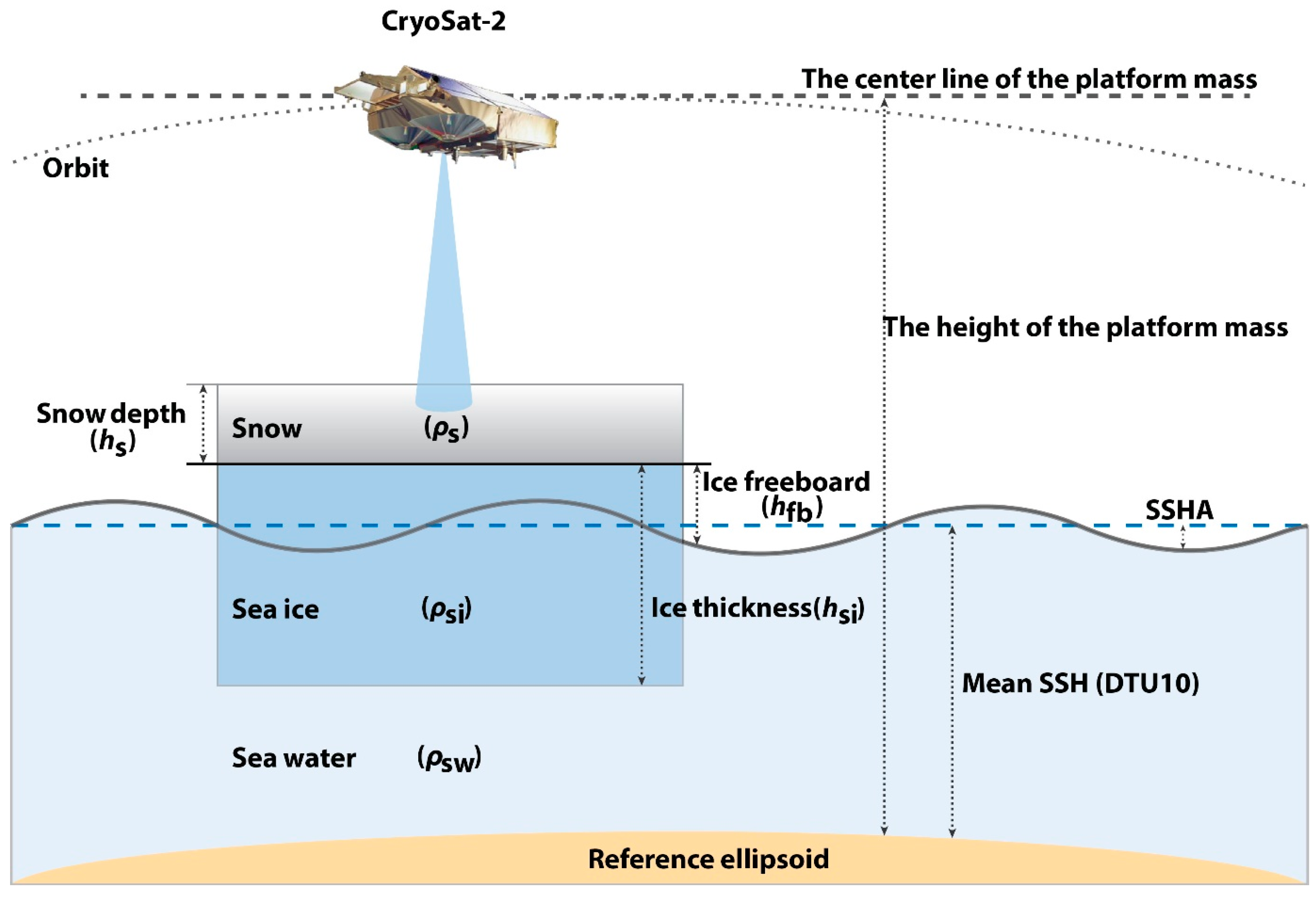
Estimation of the snow-covered Arctic sea ice thickness from CryoSat-2 measurements is based on the assumption of hydrostatic equilibrium [18] (Figure 1). If the sea ice freeboard ( h f b ) is accurately determined from altimeter measurements, the freeboard can be directly converted into sea ice thickness by Equation (1).
h s i = ρ s w   ρ s w ρ s i h f b + ρ s   ρ s w ρ s i h s
where ρ s w , ρ s i and ρ s are the density of sea water, sea ice and snow, respectively, and h s is the snow depth. Although the density parameters and snow depth should be observed concurrently with the altimeter measurements to best estimate the ice thickness, this is challenging due to the extreme weather conditions of the Arctic Ocean. Thus, studies have used typical values based on field measurements or numerical simulation. For example, Giles et al. [32] and Wadhams [10] used the density of sea water, sea ice and snow as 1023.8 ± 3, 915.1 ± 5 and 319.5 ± 3 kg/m3, respectively, from field observations. In this study, 916.7 kg/m3 and 882 kg/m3 were used as the density of FYI and MYI, respectively, according to Alexandrov et al. [33]. Snow depth simulated by the Warren 99 (hereafter W99) climatology model of Warren et al. [34] has been widely applied. However, the original W99 data only capture the seasonal variability of snow depth. Kurtz and Farrell [35] thus applied a modification to the snow depth data to reflect the significant decline in MYI over the last few years. Kurtz and Farrell [35] suggested reducing the snow depth over FYI by 50%. In this study, FYI and MYI were discriminated by the ice type products derived by EUMETSAT OSI SAF, and we used the typical density and snow depth values derived by Kurtz and Farrell [35].
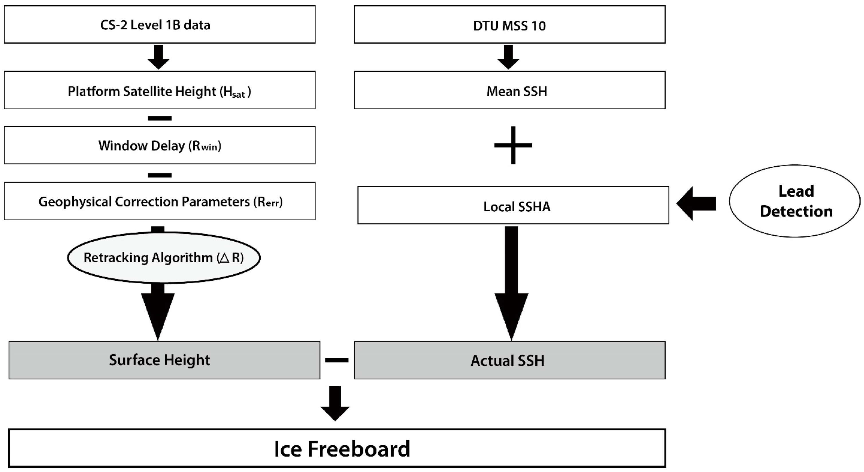
As mentioned above, it is important to determine the sea ice freeboard from CryoSat-2 data in order to successfully estimate the ice thickness. Figure 2 shows the procedure to determine the sea ice freeboard from CryoSat-2 L1B data. Initially, the surface height of the sea ice (i.e., the distance between the sea ice surface and the WGS84 ellipsoid) is estimated by Equation (2).
η s e a   i c e = H s a t R w i n R e r r Δ R
where H s a t is the height of the satellite platform mass above the WGS84 ellipsoid. R w i n is the window delay field, which means the distance between the mid-point of the range bin (i.e., 64th range bin in SAR mode and 256th range bin in SIN mode) of the waveform data and the satellite platform. R e r r is a range correction term associated with the phase range due to geophysical properties, such as atmospheric effects. These variables are given in CryoSat-2 L1B data; detailed descriptions and processing methods of the variables are well explained in [25]. Δ R is another correction term derived by various retracking methods [36,37,38,39]. The aim of these terms is to determine the range offset between the mid-point of the range bin and a realistic range point of the leading edge of sea ice. The retracking method used in this study is the Threshold First Maximum Retracker Algorithm (TFMRA) [16,18,19].
Davis [37] introduced the threshold retracking concept, which is useful for measuring the surface elevations of ice sheets or sea ice from radar altimeter data [14,19]. The retracking method determines the range point of the leading edge between the threshold level and the range point of the first maximum power peak. The threshold level ( ρ l ) is determined by:
ρ l =   P n + α ( P m a x P n )   h e r e ,     P n = 1 5 i = n ¯ n ¯ + 4 P i
where P n is the thermal noise of the CryoSat-2 system. α is the threshold value, the percentage of the maximum waveform amplitude above the thermal noise. P m a x is the first maximum power of the waveform. n ¯ is the range bin of the first unaliased waveform. P i is the power at the i -th range bin of the waveform. Finally, the retracking point ( n r ) as the leading edge is estimated using the following equation.
  n r = ( n ^ 1 ) + ρ l P n ^ 1 P n ^ P n ^ 1
where n ^ is the first range point exceeding the threshold level. It is essential to detect the first peak in the range bin. Here, Rose [16] indicated that the maximum power peak in the range bin may not be the first peak due to time delay effects of complicating factors, such as multiple scattering (i.e., in the surface) and volume scattering. Thus, the true range point (i.e., local maxima in the waveform) is detected by the peak detection algorithm, which identifies the range point using derivatives of the waveform signal [19,40]. Lastly, Δ R , the retracking correction, is calculated using Equation (5).
Δ R = C 2 m ( n r   n t r )
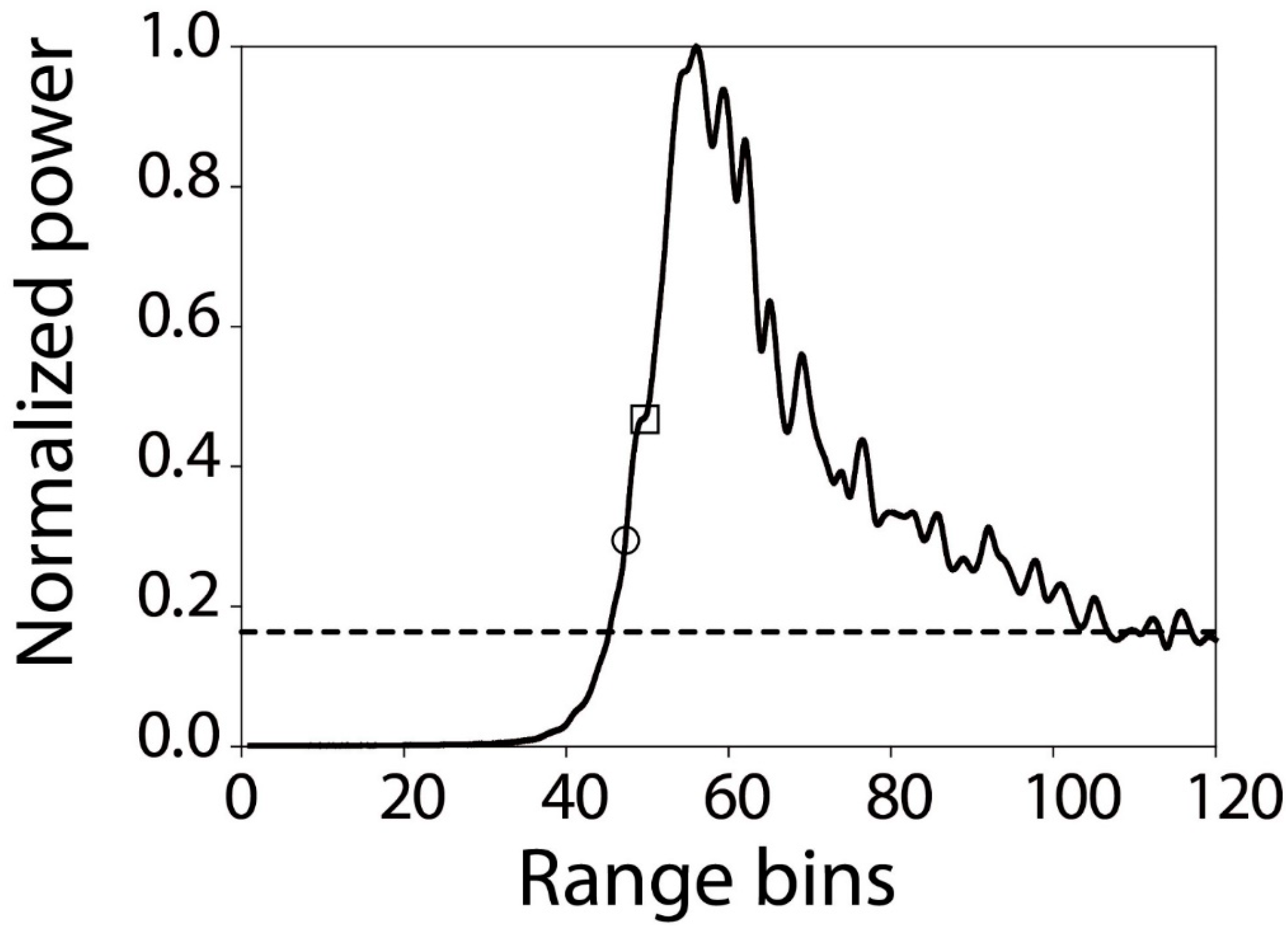
where n r is the retracking point and n t r is an on-board retracking point. C 2 m is a factor to convert from range bins to meters, which is 23.24 cm/bin for CryoSat-2. Figure 3 shows an example of the peak detection algorithm. This figure illustrates that the range point of the first maximum power (the open square) was found prior to the maximum power peak, and the retracking point (the open circle) was determined between the range point of the first maximum power and the threshold level (the dotted line). While various threshold values   ( α ) have been used in the literature, several studies have found that thresholds of 40% and 50% give the best result for determining the leading edge of the ice floe [16,40]. A threshold of 40% was used in the retracking method in this study as it was frequently used in the literature [16,19].
The next step removes the distance between the actual sea surface and the WGS84 ellipsoid from the surface height (ηsea_ice) in order to estimate the sea ice freeboard. In general, the actual Sea Surface Height (SSH) is estimated from the sum of the mean SSH and local Sea Surface Height Anomaly (SSHA). Mean SSH data were obtained from the Technical University of Denmark 10 (DTU10) product [41]; local SSHA data were derived from the proposed lead detection method (Section 3.2) that extracts leads from CryoSat-2 data. The SSHA observations were discontinuous because leads were detected at irregular intervals, thus linear interpolation and low-pass filtering were applied to make spatially-continuous SSHA. The local SSHA was used to remove the surface height from the mean SSH at the leads. Although many studies have tried to develop effective lead detection methods, it is still very difficult to accurately identify leads due to limited reference data, the irregular shape and size of leads and the characteristics leads share with ice or ocean. To overcome these challenges and correctly identify leads, this study proposed a novel lead detection method explained in Section 3.2.
A correction to the sea ice thickness estimates from freeboard should be applied to account for the penetration of microwave radiation on snow and lower propagation speed in the snow pack. First of all, while typical microwave pulses do not penetrate the snow surface when the snow layer is wet during the melting season, it is well known that a Ku-band microwave penetrates the air/snow interface of dry and cold snow during the freezing season [42,43,44]. This complexity makes it difficult to determine the optimum penetration depth to correct the sea ice freeboard. Nevertheless, Laxon et al. [18] believed that microwaves fully penetrate the snow layer. Since the speed of microwave is typically lower in the snow pack [45], it should also be corrected. However, given the uncertainty in these corrections, we did not apply the correction terms in order to enable consistent comparison with Laxon et al. [18] and Ricker et al. [19], who did not apply these corrections.

3.2. Machine Learning Algorithms for Lead Detection

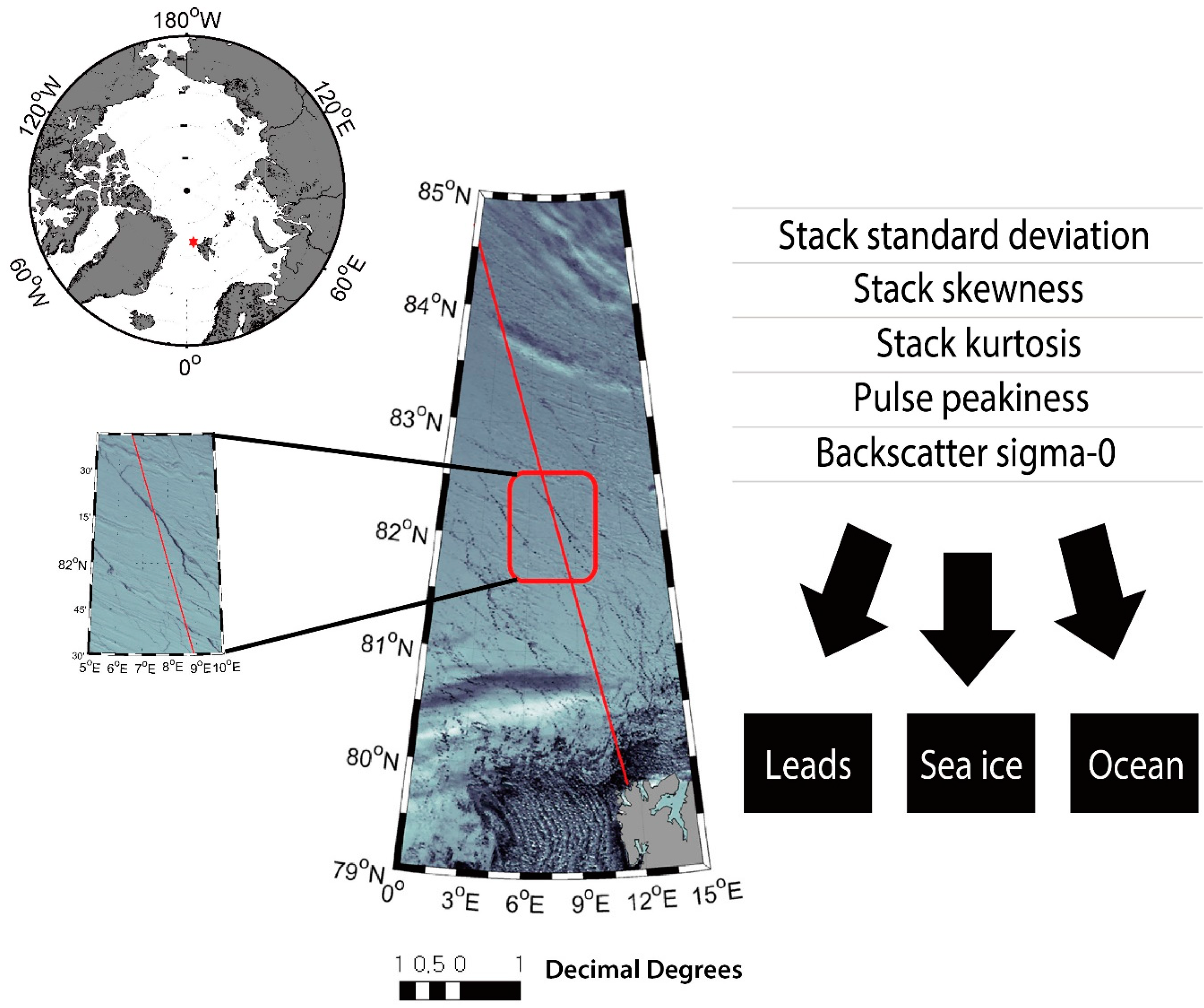
In order to detect leads using machine learning approaches, reference samples were extracted using MODIS data. All 5-min MOD02QKM images above latitude 65°N in March and April 2011–2014 were downloaded. Cloud-free images were selected through visual interpretation. A total of 48 cloud-free March and April images were selected from MOD02QKM between 2011 and 2014 to clearly identify sea ice, leads and ocean based on visual interpretation of the images (Figure 4). However, visual interpretation with MODIS is not always reliable because the leads in the MODIS images could refreeze, and new thin ice is formed. CryoSat-2 paths were geolocated over the MODIS images to extract five parameters (i.e., SSD, stack skewness, stack kurtosis, PP and backscatter sigma-0) for each class (i.e., lead, sea ice and ocean). The time difference between CryoSat-2 paths and MODIS images was set to within 30 min (12 min on average) to minimize sampling errors as sea ice sometimes moves fast. Since there were more leads found in the Arctic in April than March, the number of samples for April was larger than that for March. It should be noted that we could not extract samples all over the Arctic Region because spatiotemporal coincidence between CryoSat-2 and MODIS was limited during the given time period. Lead reference samples were not collected when the size of leads was smaller than 250 m considering the movement velocity of sea ice.
Since the characteristics of the sea ice surface have monthly and annual variations, three schemes were examined to develop machine learning models in this study. The first scheme was Classification of Monthly data (CM), which used the reference samples by month regardless of year and developed the machine learning models for both months (i.e., March and April). The second was Classification of Annual data (CA), which divided the samples by year and developed the models separately for each year (i.e., 2011, 2012, 2013 and 2014). Individual Classifications (IC) used all reference data to develop the machine learning models to consider the tradeoff between transferability and accuracy.
In order to detect leads, we used two rule-based machine learning approaches: decision trees and random forest. Decision trees are one of the most widely-used machine learning algorithms for inductive inference [46,47,48]. To implement decision trees, See 5.0 was used. See 5.0 recursively splits training data into subdivisions based on a set of attributes defined at each node in a tree [49]. An attribute is selected at each node and two branches that descend from that node use a value of the attribute as a threshold. Selecting an attribute (i.e., STD, stack skewness, stack kurtosis, PP or backscatter sigma-0 in this study) at each node is crucial for successful classification. In general, statistical properties, such as information gain or the Gini index, are used to choose an appropriate attribute in decision trees. See 5.0 uses information gain to select which candidate attribute is used at each node. See 5.0 has been widely used for various remote sensing applications, including land cover/land use classification [50,51,52], climate region delineation [53], vegetation species mapping [54,55], ice mapping [56] and change detection [57,58]. Using a See 5.0 decision tree has some advantages. First, it provides a non-parametric classification, and thus, it does not require any assumptions in terms of the distribution of training data. See 5.0 can also handle non-linear relationships between classes and features, even with missing values. In addition, See 5.0 transforms a decision tree into a series of production rulesets, which makes it easier and more straightforward for human interpretation of the results.
Random forest uses an ensemble approach that combines a boosting sampling strategy and Classification And Regression Trees (CART) [59] to improve the weaknesses of a single CART such as overfitting and sensitivity to training data configuration. CART uses a Gini index to measure impurity from training samples, while See 5.0 uses the concept of entropy. The Gini index is defined as shown in Equation (6)
Gini index ( S ) = 1 i = 1 c p i 2
where c is the number of classes and p i is the proportion of S belonging to class i. The Gini gain is used to identify the most appropriate attribute at each node. Since it is similar to the information gain, it is defined by replacing the entropy with the Gini index in the Equation (6). However, a single CART is often unstable and tends to overfit training data. Bagging can overcome such weaknesses by creating n independent trees and help minimize errors that can be caused from unstable classifiers [60]. Random forest produces numerous independent trees through two bagging-based randomization processes: (1) using a random subset of training data for each tree; and (2) using a random subset of input variables at each node of a tree. Breiman [58] pointed out that it is not necessary to use a separate dataset for model validation, as random forest uses out-of-bag data (i.e., training data that are not used) for internal cross-validation. A majority voting strategy is used to combine the results from multiple classifiers to determine the final class for a given sample. In addition, random forest provides the relative importance of a variable using out-of-bag data when the variable is permuted. Because of these strengths, random forest has proven robust in various remote sensing applications [61,62,63,64,65,66,67,68].

4. Results and Discussion

4.1. Typical Waveform over Leads, Ice Floes and Ocean

Radar signals of each of the three target features have different characteristics because of the impact of several factors, especially surface roughness, on the signals. In particular, flat surfaces produce strong signals, and rough surfaces produce weak signals. The shape of the typical waveform of ice floes is similar to that of ocean (Figure 5a,b). The sea ice waveform has large variation as it contains both diffuse (e.g., from ice floes and ridges) and specular (e.g., from lead and new ice) signals. In particular, since the surface of MYI is rougher than that of FYI, more diffuse reflection occurs on MYI. Leads have a typical specular reflection and symmetric waveform because they are relatively flat and there is little surface wave in leads (Figure 5c).

4.2. Characteristics of Five Parameters Based on CryoSat-2 Waveform

Figure 6 depicts the box plots of the five parameters (i.e., SSD, stack skewness, stack kurtosis, PP and backscatter sigma-0) by feature (i.e., leads, sea ice and ocean) using the reference samples (refer to Table 3). Among the three target features, ocean showed the narrowest distribution for all parameters, except SSD. This is because the ocean surface is relatively homogeneous. Since the state of the sea ice surface varies significantly, all parameters resulted in a wide distribution in the sea ice plots. Waveform over ocean generally has higher backscattered signal intensity than that over sea ice because of the higher diffuse reflection of ocean. However, the backscatter sigma-0 value of ocean was lower than that of sea ice (Figure 6). This might be because the ocean samples were mostly collected around the Svalbard islands, where strong winds frequently cause high waves, which may reduce the backscattered intensity. Leads showed large variation for all parameters because the size and shape of leads were diverse with different neighboring environments, such as sea ice melting states, combined with the samples being collected in March and April across multiple years, which undoubtedly increased the variation of the parameter values. The range stacked power of single look echoes from leads are similarly high because leads are relatively flat with little waves, which makes SSD of leads low with a narrow distribution in Figure 6. On the other hand, SSDs for sea ice and ocean have a broad distribution due to the surface roughness and waves. The median values of each parameter seem to distinguish lead, sea ice and ocean. However, the distribution of the parameter values of sea ice and leads partly overlapped, possibly due to off-nadir observations of CryoSat-2. This implies that simple thresholding approaches are not suitable to clearly identify leads from sea ice.

4.3. Comparison of Lead Detection Performance

Both See 5.0 and random forest produced similar classification results for the three features. Table 4 summarizes the overall accuracy by model and scheme through 10-fold cross-validation. All of the cases produced very high overall accuracy (>90%). The most common misclassification for both approaches was between leads and sea ice, possibly due to sampling around the boundaries between them. Since CM and CA resulted in varied accuracy patterns and did not produce significantly higher accuracy than IC, we focused the following discussion on IC. Using IC can reduce temporal variability by including all samples in the subsequent analyses, including sea ice freeboard and thickness estimation.
Table 5 presents relative variable importance for lead classification by model when using IC. While stack skewness and sigma-0 were used at every node in See 5.0, SSD was not used at all. For the random forest analysis, sigma-0 was identified as the predominant contributing variable, followed by stack kurtosis, PP and stack skewness. Similar to See 5.0, SSD was the least contributing variable to lead detection in random forest. Stack skewness was useful because it was able to distinguish ocean from leads and sea ice with very low error. Interestingly, backscatter sigma-0 was considered a critical parameter for lead detection in both See 5.0 and random forest, but it has not been used in previous studies for lead detection. Backscatter sigma-0 represents not only surface roughness, but also dielectric properties, radar frequency, incidence angle and geometric shape, while the other parameters are mainly sensitive to surface roughness [39]. Table 6 summarizes threshold-based rules produced using See 5.0 by IC. Previous studies have used SSD, for example, Laxon et al. [18] and Ricker et al. [19] used SSD <4 as one of the conditions to detect leads. However, SSD was not primarily used in the threshold-based rules in this study. It should be noted that the rules were an integration of multiple factors, which implies that the simple thresholding approaches might over- or under-estimate leads resulting in uncertainty in sea ice thickness estimation.
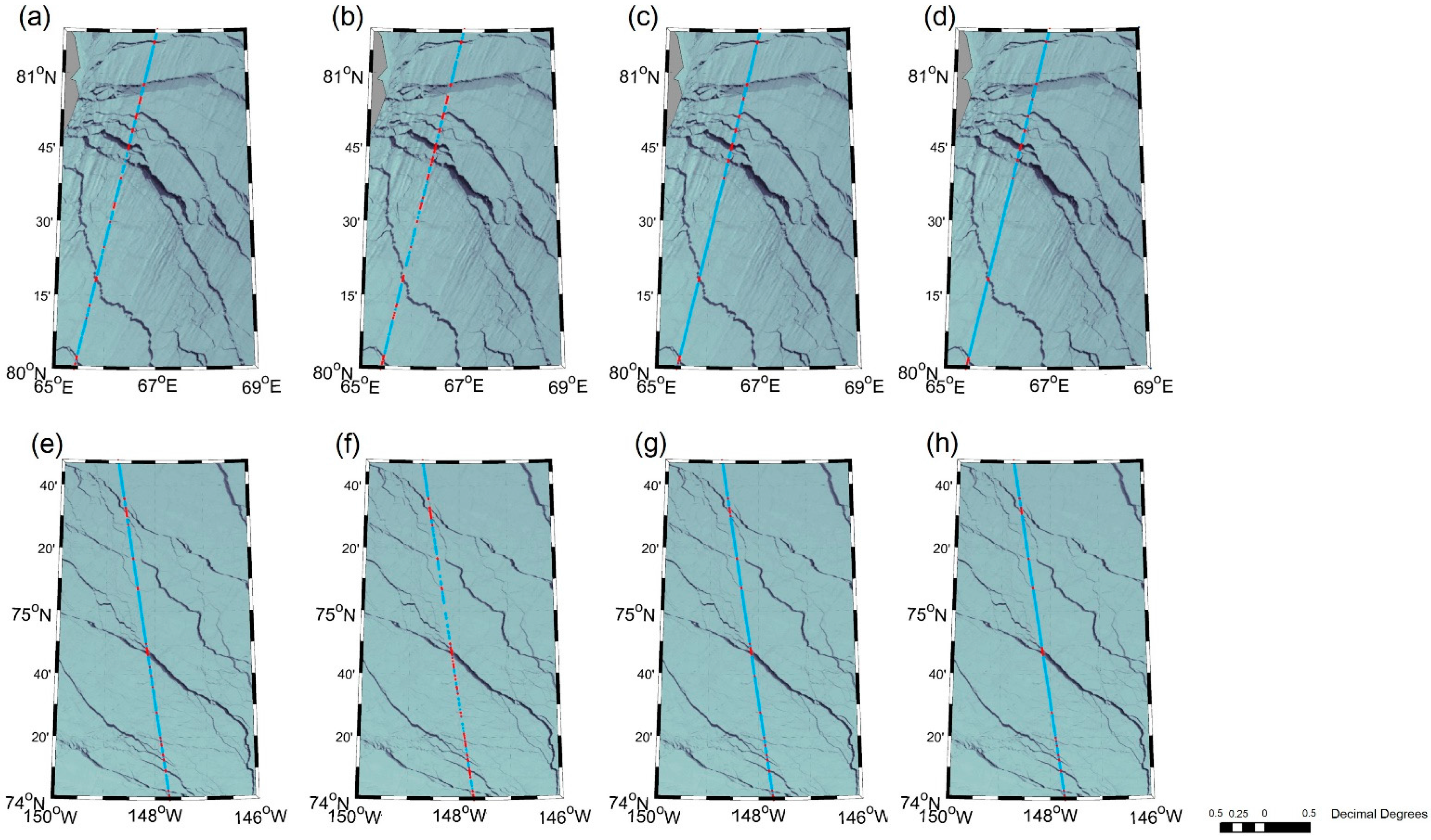
Figure 7 shows two examples of identifying leads using four different lead detection methods. A simple thresholding approach based on PP and SSD (i.e., PP > 0.25 and SSD < 4 for leads and PP < 0.45 and SSD > 4 for ice floes) used in Rose [16] was adopted to identify leads (Figure 7a,e). The simple thresholding method resulted in somewhat over-identification of leads; some leads were mistakenly found on the ice. Laxon et al. [18] also used a similar thresholding approach based on PP [69] and SSD (leads: PP > 18 and SSD < 4; ice floes: PP < 9 and SSD > 4), which also resulted in overestimation of leads on the ice (Figure 7b,f). Although PP and SSD are considered useful parameters for lead detection, simple thresholding based on just two parameters appears insufficient for effectively distinguishing leads from ice. Since surface height on leads is considered as LSSH, if leads are identified on the ice, then LSSH would be overestimated, which would result in an increased bias towards smaller freeboard and thinner sea ice estimates. On the other hand, the two machine learning approaches applied—See 5.0 decision trees and random forest—resulted in improved lead detection and less overestimation of leads compared with the existing approaches (Figure 7c,g,d,h, respectively). Different lead detection approaches were quantitatively assessed and compared (Table 7, Table 8, Table 9 and Table 10) using error matrices. Since the approaches by Rose [16] and Laxon et al. [18] considered ice floes and leads only, i.e., excluding ocean, the accuracy assessment was conducted without ocean samples for consistent comparison between the proposed approaches and the existing literature. The machine learning approaches to lead detection resulted in higher overall accuracy and Kappa coefficients than the approaches used by Rose [16] and Laxon et al. [18]. Both See 5.0 and random forest produced high producer’s accuracy for leads and sea ice. However, the user’s accuracy for leads, as well as overall accuracy and kappa coefficient of random forest were slightly higher than those of See 5.0. Random forest uses an ensemble approach based on numerous independent trees through randomization, which can avoid problems associated with sampling biases. On the other hand, See 5.0 uses only a single tree, but provides more straightforward rules to understand the results at the cost of possible overfitting and sampling biases. Based on the lead detection results in this study, both See 5.0 and random forest can be used to identify leads with minimal difference in the performance. However, in order to analyze the physical meaning among the parameters for lead detection, See 5.0 would be better, as it provides rulesets in simple forms, compared to the ensemble results of random forest. While all four lead detection methods have high producer’s accuracy for both leads and sea ice, the existing approaches (i.e., Rose [16] and Laxon et al. [18]) produced much lower user’s accuracy for leads than the proposed methods, implying the overestimation of leads.
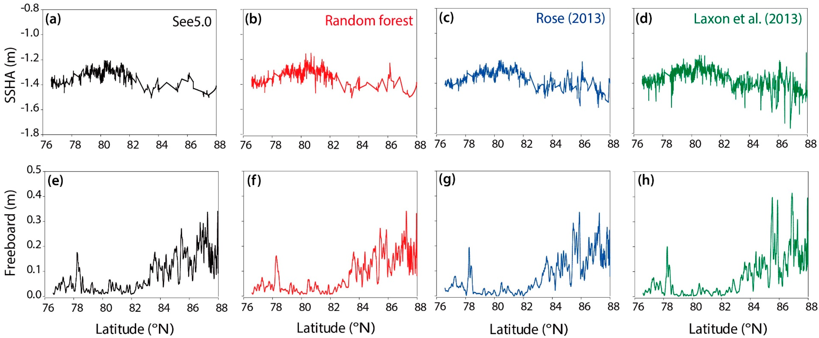
Figure 8 shows the comparison of the SSHA and freeboard from the different lead detection methods. SSHA is a subtraction of LSSH from the mean SSH, representing the relative vertical location of leads. The proposed machine learning-based lead detection methods (Figure 8a,b) detected fewer leads than the existing methods (Figure 8c,d) with few leads above the latitude of 87°N, where leads are rarely found in April. Almost all of the leads detected by the proposed See 5.0 and random forest approaches were also detected by the approaches from Laxon et al. [18] and Rose [16]. SSHA was linearly interpolated and smoothed using a 3 × 3 (pixel) moving average filter. The freeboard, a derivation of surface height from the sum of SSHA and mean SSH, was smoothed by a 30 × 30 (pixel) moving average filter to remove signal noise. While the overall shape of the freeboard lines with latitudes looks similar, the average freeboards by approach—See 5.0, random forest, Rose [16] and Laxon et al. [18]—were 0.095 m, 0.092 m, 0.089 m and 0.090 m, respectively. The average freeboards of Rose [16] and Laxon et al. [18] were relatively underestimated compared to the freeboards by See 5.0 and random forest because of their over-identification of leads on the ice, especially over higher latitudes (>85°N; Figure 8c,d). Laxon et al. [18] found lower SSHA (Figure 8h) between 76°–80°N that appeared to be ocean. However, since the proposed machine learning-based lead detection approaches discriminate ocean from sea ice and leads, ocean was excluded in the SSHA.

4.4. Spatial Distribution of Arctic Sea Ice Freeboard and Thickness

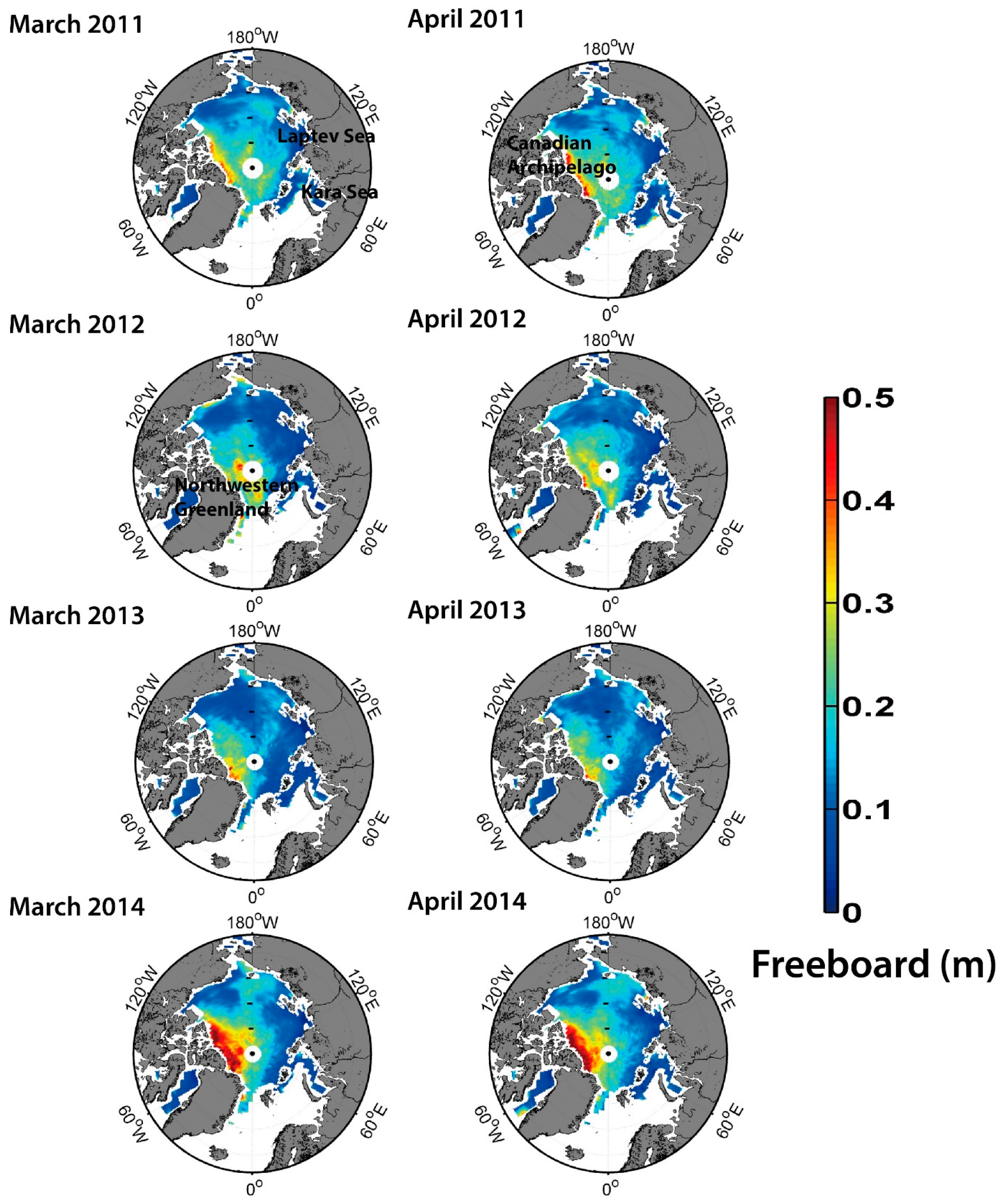
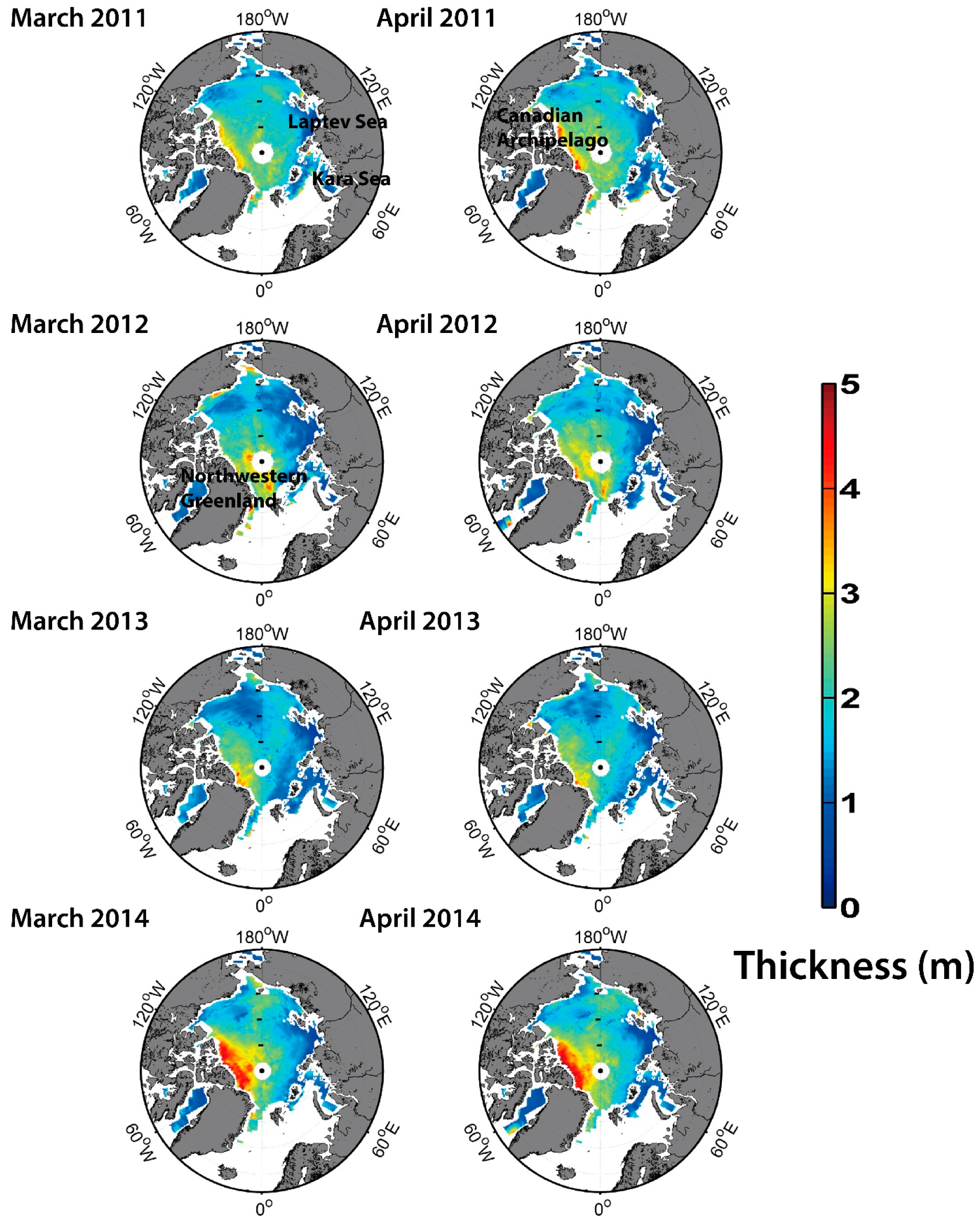
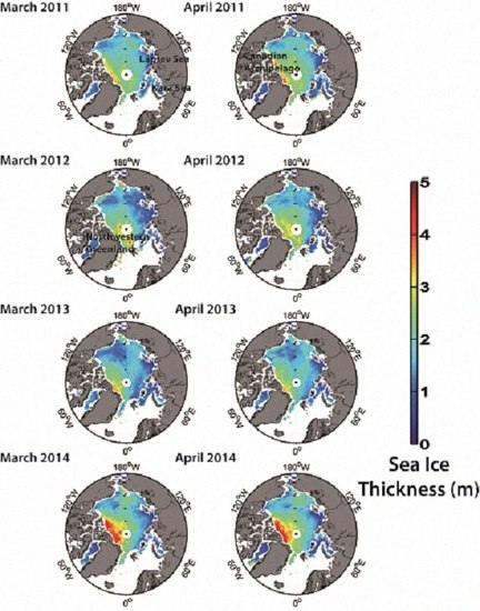
Figure 9 and Figure 10 present the IC ice freeboard and thickness maps, respectively, for March and April from 2011–2014 using a polar stereographic projection with a 25 × 25 km2 grid. A typical MYI zone near the Canadian Archipelago and northwestern Greenland has relatively thick freeboard and thickness, except for 2012. The retrieval of freeboard and thickness in these regions appears to show relatively poor LSSHA due to the very limited leads in the regions. On the other hand, sea ice freeboard and thickness around the Kara Sea and Laptev Sea were consistently stable and low for all cases during March and April from 2011–2014. Interestingly, unlike other years, sea ice thickness was relatively high in the central Arctic in 2012, while it was generally low in the typical MYI zone. The annual variability of sea ice thickness was high on the MYI zones, compared to the FYI zones. The amount of sea ice freeboard and thickness apparently diminished from 2011–2013.
Laxon et al. [18] determined Arctic sea ice thickness from February–March 2012 using CryoSat-2 data. Although it was averaged for two months, the overall distribution of sea ice thickness over MYI zones was similar to the results of this study. Sea ice freeboard and thickness maps for March 2013 from this study were slightly different from the results in Ricker et al. [19]. This is possibly because the two studies used different smoothing approaches to waveform data, lead detection methods and gridding approaches to CryoSat-2 track data. Farrell et al. [23] showed two-month averaged sea ice freeboard maps from 2003–2008 using ICESat data. However, sea ice freeboard from ICESat will be different from the sea ice freeboard determined in this study because the height of the sea ice freeboard derived by laser altimetry (i.e., from ICESat) includes snow depth on the sea ice. Farrell et al. [23] observed a slightly thicker sea ice freeboard between 2003 and 2008 (up to 0.75 m) than the 2011–2014 period in the present study. The major differences were found in the Canadian Archipelago, Northern Greenland and the central Arctic, where the freeboard was observed as being high in Farrell et al. [23], while it decreased from 2011–2013 in this study.

4.5. Comparison with AEM-Bird Data

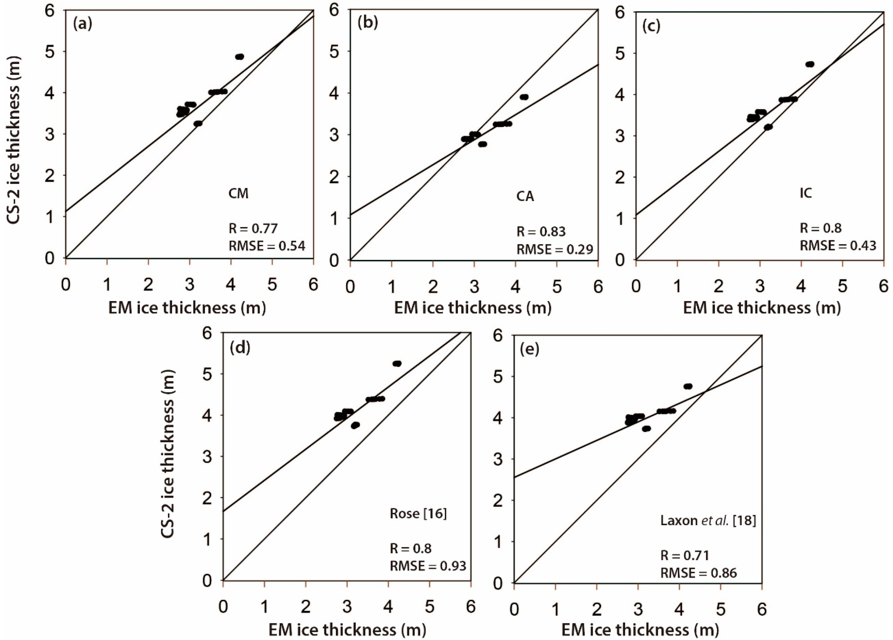
The monthly ice thickness that was averaged by grid using the novel machine learning-based lead detection approaches was compared to the averaged AEM-bird data collected 15 and 17 April 2011 during the CryoVex campaign, as well as the thickness derived by the lead detection methods from Rose [16] and Laxon et al. [18]. This comparison considered the three schemes and two lead detection methods (Figure 11). The sea ice thickness determined using See 5.0 with CA produced the best validation performance on both days with r ~ 0.83 and root mean square error (RMSE) ~0.29 m (Figure 11c).
While Rose [16] and Laxon et al. [18] produced similar performance, the sea ice thickness from See 5.0 generally showed better performance than that derived using the existing methods. However, there are several uncertainty factors for sea ice thickness estimation using CryoSat-2 measurements [19], including: (1) the error of range measurements from CryoSat-2; (2) the uncertainty of detection of leads, resulting in over- or under-estimation of SSHA; (3) the uncertainty of mean scattering horizon in the snow cover; and (4) the uncertainty of snow depth and the density of snow, ice and sea water. Zygmuntowska et al. [70] estimated the uncertainty of Arctic sea ice thickness and volume in terms of sea ice density and snow depth by using the Monte Carlo approach. They revealed that using snow loading (i.e., W99) produced higher uncertainty with respect to the estimation of sea ice thickness than using mean density. In the present study, we used the densities from Alexandrov et al. [33] that do not have year-to-year variability. In order to more accurately estimate sea ice thickness, such changes should be carefully considered, which requires further examination. Ricker et al. [19] analyzed random and systematic uncertainties of Arctic sea ice thickness from CryoSat-2 using the partial derivative of Equation (1) based on the assumption of hydrostatic equilibrium. They showed that random uncertainty affects the estimation of sea ice thickness less than systematic uncertainty caused by the selection of a retracker threshold and the unknown penetration level of the signals on snow. To remove systematic uncertainty caused by the choice of a retracker threshold, Kurtz et al. [17] used a waveform fitting approach to retrieve sea ice freeboard. Any of the above-mentioned factors could result in uncertainty in this study. The lead detection models proposed in this study produced higher accuracy than the existing approaches for lead detection, which implies a possible reduction of the uncertainty caused by the second factor.
In order to examine the influence of snow penetration on the thickness estimation, we conducted a simple sensitivity analysis on snow penetration by testing different penetration ratios with the assumption that radar signals penetrate into the snow depth with the same rate over the entire Arctic region. The results showed that higher accuracy (i.e., lower RMSE) was achieved with increasing penetration depth ratios. Nevertheless, it is difficult to quantify how many centimeters of snow the Ku-band penetrates simply because the snow penetration depth highly depends on the spatiotemporal distribution of snow and whether it is dry or wet. In order to further enhance the sea ice freeboard and thickness produced in this study, snow penetration depth should be considered.

5. Conclusions

In this study, a novel machine learning-based lead detection approach was proposed to quantify Arctic sea ice freeboard and thickness from CryoSat-2 data. The estimated sea ice thickness was validated with AEM-bird data. Accurate lead detection is crucial in estimating LSSH, which is essential to retrieve the freeboard and thickness [16,23]. The results showed that the proposed lead detection approach successfully estimated the sea ice thickness, compared to the existing methods. The overall accuracies by the proposed lead detection methods—decision trees (See 5.0) and random forest—were 95.4% and 96.2%, respectively, which were higher than those produced using the existing methods.
A total of five parameters were used to detect leads, including SSD, stack skewness, PP, stack kurtosis and backscatter sigma-0. Among the parameters, backscatter sigma-0, which prior methods had not considered, played a significant role in determining the threshold-based rules to distinguish leads from ice floes. The lead detection models developed by year or month (i.e., CM and CA) did not produce better performance than the combined model that used all samples for March and April from 2011–2014. This suggests that sea ice thickness in other months such as May or June could be retrieved when additional reference samples from the months were combined with the existing data. That way, a standard lead detection model can be proposed, which can be applied for any year and month. The results also showed that Arctic sea ice freeboard and thickness consistently decreased from 2011–2013, especially in the Canadian Archipelago region, but rebounded in 2014. Future research includes developing a machine learning-based lead detection model that can be applied to any year and month and modeling snow depth penetration using CryoSat-2 data.

Acknowledgments

This research was a part of the project titled ‘Korea-Polar Ocean in Rapid Transition (KOPRI, PM13020)’, funded by the Ministry of Oceans and Fisheries, Korea. This research was also supported by the SaTellite remote sensing on set Antarctic ocean Research (STAR) project (KOPRI, PE15040), funded by the Korea Polar Research Institute, South Korea.

Author Contributions

Sanggyun Lee led the manuscript writing and contributed to the data analysis and research design. Jungho Im supervised this study, contributed to the research design and manuscript writing and serves as the corresponding author. Jinwoo Kim, Miae Kim and Minso Shin contributed to data processing and analysis and the discussion of the results. Hyon-cheol Kim and Lindi Quackenbush contributed to the discussion of results and the manuscript writing.

Conflicts of Interest

The authors declare no conflict of interest.

References

  1. Screen, J.A.; Simmonds, I. The central role of diminishing sea ice in recent arctic temperature amplification. Nature 2010, 464, 1334–1337. [Google Scholar] [CrossRef] [PubMed] [Green Version]
  2. Laine, V. Arctic sea ice regional albedo variability and trends, 1982–1998. J. Geophys. Res. Oceans 2004, 109, C06027. [Google Scholar] [CrossRef]
  3. Lindsay, R.W. Arctic sea-ice albedo derived from RGPS-based ice-thickness estimates. Ann. Glaciol. 2001, 33, 225–229. [Google Scholar] [CrossRef]
  4. Parkinson, C.L.; Cavalieri, D.J. Arctic sea ice variability and trends, 1979–2006. J. Geophys. Res. Oceans 2008, 113, C07003. [Google Scholar] [CrossRef]
  5. Kang, D.; Im, J.; Lee, M.; Quackenbush, L.J. The MODIS ice surface temperature product as an indicator of sea ice minimum over the Arctic Ocean. Remote Sens. Environ. 2014, 152, 99–108. [Google Scholar] [CrossRef]
  6. Boe, J.; Hall, A.; Qu, X. September sea-ice cover in the arctic ocean projected to vanish by 2100. Nat. Geosci. 2009, 2, 341–343. [Google Scholar] [CrossRef]
  7. Stroeve, J.; Holland, M.M.; Meier, W.; Scambos, T.; Serreze, M. Arctic sea ice decline: Faster than forecast. Geophys. Res. Lett. 2007, 34, L09501. [Google Scholar] [CrossRef]
  8. Wang, M.; Overland, J.E. A sea ice free summer arctic within 30 years: An update from CMIP5 models. Geophys. Res. Lett. 2012, 39, L18501. [Google Scholar] [CrossRef]
  9. Rothrock, D.A.; Yu, Y.; Maykut, G.A. Thinning of the arctic sea-ice cover. Geophys. Res. Lett. 1999, 26, 3469–3472. [Google Scholar] [CrossRef]
  10. Wadhams, P. Ice thickness in the arctic ocean: The statistical reliability of experimental data. J. Geophys. Res. Oceans 1997, 102, 27951–27959. [Google Scholar] [CrossRef]
  11. Eicken, H.; Tucker, W.B.; Perovich, D.K. Indirect measurements of the mass balance of summer arctic sea ice with an electromagnetic induction technique. Ann. Glaciol. 2001, 33, 194–200. [Google Scholar] [CrossRef]
  12. Haas, C.; Hendricks, S.; Doble, M. Comparison of the sea-ice thickness distribution in the Lincoln Sea and adjacent Arctic Ocean in 2004 and 2005. Ann. Glaciol. 2006, 44, 247–252. [Google Scholar] [CrossRef]
  13. Haas, C.; Lobach, J.; Hendricks, S.; Rabenstein, L.; Pfaffling, A. Helicopter-borne measurements of sea ice thickness, using a small and lightweight, digital EM system. J. Appl. Geophys. 2009, 67, 234–241. [Google Scholar] [CrossRef] [Green Version]
  14. Laxon, S.; Peacock, N.; Smith, D. High interannual variability of sea ice thickness in the arctic region. Nature 2003, 425, 947–950. [Google Scholar] [CrossRef] [PubMed]
  15. Kwok, R.; Cunningham, G.F.; Zwally, H.J.; Yi, D. Ice, cloud, and land elevation satellite (ICESat) over arctic sea ice: Retrieval of freeboard. J. Geophys. Res. Oceans 2007, 112, C12013. [Google Scholar] [CrossRef]
  16. Rose, S. Measurements of Sea Ice by Satellite and Airborne Altimetry. Ph.D. Thesis, Technical University of Denmark, National Space Institute, Lyngby, Denmark, 2013. [Google Scholar]
  17. Kurtz, N.T.; Galin, N.; Studinger, M. An improved CryoSat-2 sea ice freeboard retrieval algorithm through the use of waveform fitting. Cryosphere 2014, 8, 1217–1237. [Google Scholar] [CrossRef] [Green Version]
  18. Laxon, S.W.; Giles, K.A.; Ridout, A.L.; Wingham, D.J.; Willatt, R.; Cullen, R.; Kwok, R.; Schweiger, A.; Zhang, J.; Haas, C.; et al. CryoSat-2 estimates of arctic sea ice thickness and volume. Geophys. Res. Lett. 2013, 40, 732–737. [Google Scholar] [CrossRef]
  19. Ricker, R.; Hendricks, S.; Helm, V.; Skourup, H.; Davidson, M. Sensitivity of CryoSat-2 arctic sea-ice freeboard and thickness on radar-waveform interpretation. Cryosphere 2014, 8, 1607–1622. [Google Scholar] [CrossRef] [Green Version]
  20. Liu, C.; Chao, J.; Gu, W.; Xu, Y.; Xie, F. Estimation of sea ice thickness in the Bohai Sea using a combination of VIS/NIR and SAR images. GISci. Remote Sens. 2015, 52, 115–130. [Google Scholar] [CrossRef]
  21. Forsström, S.; Gerland, S.; Pedersen, C.A. Thickness and density of snow-covered sea ice and hydrostatic equilibrium assumption from in situ measurements in fram strait, the barents sea and the svalbard coast. Ann. Glaciol. 2011, 52, 261–270. [Google Scholar] [CrossRef]
  22. Zwally, H.J.; Yi, D.; Kwok, R.; Zhao, Y. Icesat measurements of sea ice freeboard and estimates of sea ice thickness in the weddell sea. J. Geophys. Res. Oceans 2008, 113, C02S15. [Google Scholar] [CrossRef]
  23. Farrell, S.L.; Laxon, S.W.; McAdoo, D.C.; Yi, D.; Zwally, H.J. Five years of arctic sea ice freeboard measurements from the ice, cloud and land elevation satellite. J. Geophys. Res. Oceans 2009, 114, C04008. [Google Scholar] [CrossRef]
  24. Onana, V.; Kurtz, N.T.; Farrell, S.L.; Koenig, L.S.; Studinger, M.; Harbeck, J.P. A sea-ice lead detection algorithm for use with high-resolution airborne visible imagery. IEEE Trans. Geosci. Remote Sens. 2013, 51, 38–56. [Google Scholar] [CrossRef]
  25. Wingham, D.J.; Francis, C.R.; Baker, S.; Bouzinac, C.; Brockley, D.; Cullen, R.; de Chateau-Thierry, P.; Laxon, S.W.; Mallow, U.; Mavrocordatos, C.; et al. CryoSat: A mission to determine the fluctuations in earth’s land and marine ice fields. Adv. Space Res. 2006, 37, 841–871. [Google Scholar] [CrossRef]
  26. European Space Agency (ESA); University College London (UCL). CryoSat Product Handbook; ESRIN-ESA and Mullard Space Science Laboratory—University College London: London, UK, 2013. [Google Scholar]
  27. Peacock, N.R.; Laxon, S.W. Sea surface height determination in the arctic ocean from ERS altimetry. J. Geophys. Res. Oceans 2004, 109, C07001. [Google Scholar] [CrossRef]
  28. European Space Agency (ESA). Beam Behavior Parameters in CryoSat Level1b Products; ESA: Paris, France, 2014. [Google Scholar]
  29. Armitage, T.W.K.; Davidson, M.W.J. Using the interferometric capabilities of the ESA CryoSat-2 mission to improve the accuracy of sea ice freeboard retrievals. IEEE Trans. Geosci. Remote Sens. 2014, 52, 529–536. [Google Scholar] [CrossRef]
  30. Salvatore, D. Guidelines for Reverting Waveform Power to Sigma Nought for CryoSat-2 in SAR Mode; European Space Agency: Paris, France, 2014. [Google Scholar]
  31. Haas, C.; Hendricks, S.; Eicken, H.; Herber, A. Synoptic airborne thickness surveys reveal state of arctic sea ice cover. Geophys. Res. Lett. 2010, 37, L09501. [Google Scholar] [CrossRef]
  32. Giles, K.A.; Laxon, S.W.; Ridout, A.L. Circumpolar thinning of Arctic sea ice following the 2007 record ice extent minimum. Geophys. Res. Lett. 2007, 35. [Google Scholar] [CrossRef]
  33. Alexandrov, V.; Sandven, S.; Wahlin, J.; Johannessen, O.M. The relation between sea ice thickness and freeboard in the Arctic. Cryosphere 2010, 4, 373–380. [Google Scholar] [CrossRef] [Green Version]
  34. Warren, S.G.; Rigor, I.G.; Untersteiner, N.; Radionov, V.F.; Bryazgin, N.N.; Aleksandrov, Y.I.; Colony, R. Snow depth on Arctic sea ice. J. Clim. 1999, 12, 1814–1829. [Google Scholar] [CrossRef]
  35. Kurtz, N.T.; Farrell, S.L. Large-scale surveys of snow depth on Arctic sea ice from Operation IceBridge. Geophys. Res. Lett. 2011, 38, L20505. [Google Scholar] [CrossRef]
  36. Brown, G.S. The average impulse response of a rough surface and its applications. IEEE Trans. Antennas Propag. 1977, 25, 67–74. [Google Scholar] [CrossRef]
  37. Davis, C.H. A robust threshold retracking algorithm for measuring ice-sheet surface elevation change from satellite radar altimeters. IEEE Trans. Geosci. Remote Sens. 1997, 35, 974–979. [Google Scholar] [CrossRef]
  38. Martin, T.V.; Zwally, H.J.; Brenner, A.C.; Bindschadler, R.A. Analysis and retracking of continental ice sheet radar altimeter waveforms. J. Geophys. Res. Oceans 1983, 88, 1608–1616. [Google Scholar] [CrossRef]
  39. Wingham, D.; Rapley, C.; Griffiths, H. New techniques in satellite altimeter tracking systems. In Proceedings of the 1986 International Geoscience and Remote Sensing Symposium (IGARSS’86) on Remote Sensing: Today’s Solutions for Tomorrow’s Information Needs, Zürich, Switzerland, 8–11 September 1986.
  40. Helm, V.; Humbert, A.; Miller, H. Elevation and elevation change of Greenland and Antarctica derived from CryoSat-2. Cryosphere 2014, 8, 1539–1559. [Google Scholar] [CrossRef] [Green Version]
  41. Andersen, O.B.; Knudsen, P. Dnsc08 mean sea surface and mean dynamic topography models. J. Geophys. Res. Oceans 2009, 114. [Google Scholar] [CrossRef]
  42. Hallikainen, M.T.; Jolma, P.A. Comparison of algorithms for retrieval of snow water equivalent from Nimbus-7 SMMR data in Finland. IEEE Trans. Geosci. Remote Sens. 1992, 30, 124–131. [Google Scholar] [CrossRef]
  43. Beaven, S.G.; Lockhart, G.L.; Gogineni, S.P.; Hossetnmostafa, A.R.; Jezek, K.; Gow, A.J.; Perovich, D.K.; Fung, A.K.; Tjuatja, S. Laboratory measurements of radar backscatter from bare and snow-covered saline ice sheets. Int. J. Remote Sens. 1995, 16, 851–876. [Google Scholar] [CrossRef]
  44. Connor, L.N.; Farrell, S.L.; McAdoo, D.C.; Krabill, W.B.; Manizade, S. Validating icesat over thick sea ice in the Northern Canada Basin. IEEE Trans. Geosci. Remote Sens. 2013, 51, 2188–2200. [Google Scholar] [CrossRef]
  45. Matzler, C.; Wegmuller, U. Dielectric properties of freshwater ice at microwave frequencies. J. Phys. D Appl. Phys. 1987, 20, 1623. [Google Scholar] [CrossRef]
  46. Im, J.; Jensen, J.R. A change detection model based on neighborhood correlation image analysis and decision tree classification. Remote Sens. Environ. 2005, 99, 326–340. [Google Scholar] [CrossRef]
  47. Jensen, J.R. Introductory Digital Image Processing: A Remote Sensing Perspective, 4th ed.; Prentice Hall: New York, NY, USA, 2014. [Google Scholar]
  48. Gleason, C.J.; Im, J. Forest biomass estimation from airborne LiDAR data using machine learning approaches. Remote Sens. Environ. 2012, 125, 80–91. [Google Scholar] [CrossRef]
  49. Quinlan, J.R. Data mining tools See 5 and C5.0. St. Ives, NSW, Australia: Rule-Quest Research. Available online: http://www.rulequest.com/see5-info.html (accessed on 25 February 2013).
  50. Im, J.; Lu, Z.; Rhee, J.; Quackenbush, L. Impervious surface quantification using a synthesis of artificial immune networks and decision/regression trees from multi-sensor data. Remote Sens. Environ. 2012, 117, 102–113. [Google Scholar] [CrossRef]
  51. Im, J.; Jensen, J.R.; Hodgson, M.E. Object-based land cover classification using high-posting-density lidar data. GISci. Remote Sens. 2008, 45, 209–228. [Google Scholar] [CrossRef]
  52. Lu, Z.; Im, J.; Rhee, J.; Hodgson, M. Building type classification using spatial and landscape attributes derived from lidar remote sensing data. Landsc. Urban Plan. 2014, 130, 134–148. [Google Scholar] [CrossRef]
  53. Rhee, J.; Im, J.; Carbone, G.J.; Jensen, J.R. Delineation of climate regions using in-situ and remotely-sensed data for the Carolinas. Remote Sens. Environ. 2008, 112, 3099–3111. [Google Scholar] [CrossRef]
  54. Li, M.; Im, J.; Beier, C. Machine learning approaches for forest classification and change analysis using multi-temporal Landsat TM images over huntington wildlife forest. GISci. Remote Sens. 2013, 50, 361–384. [Google Scholar]
  55. Im, J.; Jensen, J.; Jensen, R.; Gladden, J.; Waugh, J.; Serrato, M. Vegetation cover analysis of hazardous waste sites in Utah and Arizona using hyperspectral remote sensing. Remote Sens. 2012, 4, 327–353. [Google Scholar] [CrossRef]
  56. Kim, M.; Im, J.; Han, H.; Kim, J.; Lee, S.; Shin, M.; Kim, H.-C. Landfast sea ice monitoring using multisensor fusion in the Antarctic. GISci. Remote Sens. 2015, 52, 239–256. [Google Scholar] [CrossRef]
  57. Torbick, N.; Corbiere, M. Mapping urban sprawl and impervious surfaces in the northeast United States for the past four decades. GISci. Remote Sens. 2015, 52, 746–764. [Google Scholar] [CrossRef]
  58. Jensen, J.; Im, J. Remote sensing change detection in urban environments. In Geo-Spatial Technologies in UrbanEnvironments, 2nd ed.; Springer: Berlin, Germany, 2007; pp. 7–31. [Google Scholar]
  59. Breiman, L. Random forests. Mach. Learn. 2001, 45, 5–32. [Google Scholar] [CrossRef]
  60. Chan, J.C.W.; Paelinckx, D. Evaluation of Random Forest and Adaboost tree-based ensemble classification and spectral band selection for ecotope mapping using airborne hyperspectral imagery. Remote Sens. Environ. 2008, 112, 2999–3011. [Google Scholar] [CrossRef]
  61. Kim, Y.H.; Im, J.; Ha, H.K.; Choi, J.-K.; Ha, S. Machine learning approaches to coastal water quality monitoring using GOCI satellite data. GISci. Remote Sens. 2014, 51, 158–174. [Google Scholar] [CrossRef]
  62. Long, J.A.; Lawrence, R.L.; Greenwood, M.C.; Marshall, L.; Miller, P.R. Object-oriented crop classification using multitemporal ETM+ SLC-off imagery and random forest. GISci. Remote Sens. 2013, 50, 418–436. [Google Scholar]
  63. Maxwell, A.E.; Strager, M.P.; Warner, T.A.; Zégre, N.P.; Yuill, C.B. Comparison of NAIP orthophotography and RapidEye satellite imagery for mapping of mining and mine reclamation. GISci. Remote Sens. 2014, 51, 301–320. [Google Scholar] [CrossRef]
  64. Rhee, J.; Park, S.; Lu, Z. Relationship between land cover patterns and surface temperature in urban areas. GISci. Remote Sens. 2014, 51, 521–536. [Google Scholar] [CrossRef]
  65. Ghimire, B.; Rogan, J.; Galiano, V.R.; Panday, P.; Neeti, N. An evaluation of bagging, boosting, and random forests for land-cover classification in Cape Cod, Massachusetts, USA. GISci. Remote Sens. 2012, 49, 623–643. [Google Scholar] [CrossRef]
  66. Im, J.; Jensen, J.; Coleman, M.; Nelson, E. Hyperspectral remote sensing analysis of short rotation woody crops grown with controlled nutrient and irrigation treatments. Geocarto Int. 2009, 24, 293–312. [Google Scholar] [CrossRef]
  67. Han, H.; Lee, S.; Im, J.; Kim, M.; Lee, M.; Ahn, M.; Chung, S. Detection of convective initiation using Meteorological Imager onboard Communication, Ocean, and Meteorological Satellite based on machine learning approaches. Remote Sens. 2015, 7, 9184–9204. [Google Scholar] [CrossRef]
  68. Park, S.; Im, J.; Jang, E.; Rhee, J. Drought assessment and monitoring through blending of multi-sensor indices using machine learning approaches for different climate regions. Agric. For. Meteorol. 2016, 216, 157–169. [Google Scholar] [CrossRef]
  69. Ridout, A.; University College London, London, UK. Personal communication, 2015.
  70. Zygmuntowska, M.; Rampal, P.; Ivanova, N.; Smedsrud, L.H. Uncertatinty in Arctic sea ice thickness and volume: New estimates and implicatoins for trends. Cryosphere 2014, 8, 705–720. [Google Scholar] [CrossRef]
Figure 1. Schematic diagram of the freeboard and thickness processing from CryoSat-2. SSHA, Sea Surface Height Anomaly.
Remotesensing 08 00698 g001
Figure 2. The sea ice freeboard processing procedure using CryoSat-2 data.
Remotesensing 08 00698 g002
Figure 3. A typical waveform of sea ice from CryoSat-2 data. The dotted line denotes the threshold level estimated by the threshold retracking method ( α   = 40%). The open square indicates the range point of the first maximum power peak determined by the peak detection algorithm. The open circle indicates the range point of the leading edge.
Remotesensing 08 00698 g003
Figure 4. Overlay of a CryoSat-2 path on a MODIS image collected on 6 April 2011. The CryoSat-2 path (red line) was geolocated on the MODIS image in the north of Svalbard. The time difference between the two was six minutes. Based on visual interpretation, five parameters were extracted for target features (i.e., leads, sea ice and ocean).
Remotesensing 08 00698 g004
Figure 5. Typical normalized echo power waveform of CryoSat-2 SAR mode data over: (a) sea ice; (b) ocean; and (c) leads.
Remotesensing 08 00698 g005
Figure 6. Box plots of five parameters (i.e., SSD, stack skewness, stack kurtosis, PP and backscatter sigma-0) over leads, sea ice and ocean using the March and April samples from 2011–2014. The vertical height of the boxes indicates the interquartile range of the samples. While a parallel line inside the boxes means a median value of the samples for each parameter, the dots represent the outliers.
Remotesensing 08 00698 g006
Figure 7. Examples of lead detection results around east Franz Josef Land on 11 April 2014 (ad) and Beaufort Sea on 11 April 2011(eh) using four methods: (a,e) Rose [16]; (b,f) Laxon et al. [18]; (c,g) See 5.0 in the present study and (d,h) random forest in the present study. Red and blue dots represent leads and sea ice, respectively.
Remotesensing 08 00698 g007
Figure 8. SSHA and freeboard extracted by each method using CryoSat-2 data from UTC 03:47–03:57, 9 April 2012 based on IC: (ad) are the interpolated and smoothed SSHA; (eh) the smoothed freeboard.
Remotesensing 08 00698 g008
Figure 9. Arctic sea ice freeboard from CryoSat-2 for March and April between 2011 and 2014 based on the IC scheme. Non-sea ice areas were masked out using the EUMETSAT OSI SAF sea ice type data.
Remotesensing 08 00698 g009
Figure 10. Arctic sea ice thickness from CryoSat-2 for March and April between 2011 and 2014 based on the IC scheme. Non-sea ice areas were masked out using the EUMETSAT Ocean & Sea Ice Satellite Application Facility (OSI SAF) sea ice type data.
Remotesensing 08 00698 g010
Figure 11. (ae) Scatterplots between the CryoSat-2-derived sea ice thickness and the averaged AEM-bird ice thickness for validation.
Remotesensing 08 00698 g011
Table 1. The specifications of CryoSat-2 (Synthetic Aperture Interferometric Radar Altimeter (SIRAL). LRM, Low Resolution Mode; SIN, SAR Interferometry.
CryoSat-2
Center frequency13.575 GHz
Bandwidth320 MHz
Pulse Repetition Frequency (PRF)1.97 kHz (LRM)/18.181 kHz (SAR and SIN)
Pulse duration44.8 ms
Samples in echo128 (LRM and SAR)/512 (SIN)
Antenna footprint0.29 km
Range bin sample0.4684 (LRM)/0.2342 m (SAR and SIN)
Table 2. The equations to retrieve Stack Standard Deviation (SSD), stack skewness and kurtosis, as well as Pulse Peakiness (PP) [26,28].
ParameterEquation
SSD 1 2 i = 1 N S P 2 ( i ) i = 1 N S P 2 ( i ) i = 1 N S P 4 ( i )
Stack skewness 1 N i = 1 N ( S P ( i ) μ ) 3 [ 1 N 1 i = 1 N ( S P ( i ) μ ) 2 ] 2 / 3 , μ = 1 N i = 1 N S P ( i )
Stack kurtosis 1 N i = 1 N ( S P ( i ) μ ) 4 [ 1 N 1 i = 1 N ( S P ( i ) μ ) 2 ] 3 3 , μ = 1 N i = 1 N S P ( i )
Pulse peakiness k   P m a x i = 1 n p i n = 128 (SAR) and 512 (SIN)
where SP stands for integrated stacked power that is not obtainable in the L1b data. The integrated stacked power is the summation of each single look echo power. p m a x is the maximum power of the waveform from L1b data, and p i is the power of i-th range bin. k is a multiplying factor based on the assumption that the waveform is almost centered in the range bins. A k value of 1 was used in this study following [29].
Table 3. Reference data used in the machine learning models by scheme and target feature. CM, Classification of Monthly data; CA, Classification of Annual data; IC, Individual Classification.
SchemeTarget Feature (Number of Observations)
LeadsSea IceOcean
CM (March)331660724
CM (April)64112841220
CA (2011)179357357
CA (2012)458919919
CA (2013)209419420
CA (2014)126249248
IC97219441944
Table 4. Accuracy assessment results of See 5.0 and random forest by scheme through 10-fold cross-validation. The overall accuracy in percentage averaged for 10 folds is provided.
SchemeSee 5.0Random Forest
CA (March)99.5099.43
CA (April)93.4790.40
CM (2011)92.4994.80
CM (2012)94.8796.96
CM (2013)95.0795.48
CM (2014)94.4091.60
IC94.2094.05
Table 5. Relative variable importance (i.e., contribution) to lead detection using See 5.0 and random forest by IC.
SSDStack SkewnessStack KurtosisPPSigma-0
See 5.0 Usage (%)01002140100
Random forest mean accuracy decrease (%) 19.9720.4436.7520.5097.72
Table 6. An example of threshold-based rules produced by See 5.0 using IC to classify leads, sea ice and ocean.
SSDSkewnessKurtosisPPSigma-0
Lead >0.73>17.53 >27.8
≤25.6>0.73≤17.53 >27.8
Sea ice ≤0.73 ≤14.89
≤0.73 >0.04314.89 < Sigma-0 < 16.48
>0.73 ≤27.8
≤25.6>0.73≤17.53 27.8 < Sigma-0 < 31.47
Ocean ≤0.73 ≤0.043>14.89
0.73 > 0.043 > 14.89
> 25.6 > 0.73 17.53 > 27.8
Table 7. The error matrix based on the See 5.0-based lead detection results for IC.
Reference Classified asLeadSea IceSumUser’s Accuracy (%)
Lead3654187.8
Sea ice619219896.7
Sum42197239
Producer’s accuracy (%)85.797.5
Overall accuracy (%)95.4
Kappa coefficient (%)84
Table 8. The error matrix based on the random forest-based lead detection results for IC.
Reference Classified asLeadSea IceSumUser’s Accuracy (%)
Lead3623894.7
Sea ice619520197.0
Sum42197239
Producer’s accuracy (%)85.798.9
Overall accuracy (%)96.2
Kappa coefficient (%)86.4
Table 9. The error matrix based on the lead detection results by the approach of Rose [16].
Reference Classified asLeadSea IceSumUser’s Accuracy (%)
Lead36286456.2
Sea ice616917596.7
Sum42197239
Producer’s accuracy (%)85.785.8
Overall accuracy (%)85.7
Kappa coefficient (%)59.3
Table 10. The error matrix based on the lead detection results by the approach of Laxon et al. [18].
Reference Classified asLeadSea iceSumUser’s Accuracy (%)
Lead41458647.7
Sea ice115215299.3
Sum42197239
Producer’s accuracy (%)97.677.2
Overall accuracy (%)80.7
Kappa coefficient (%)53