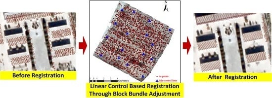
A Linear Feature-Based Approach for the Registration of Unmanned Aerial Vehicle Remotely-Sensed Images and Airborne LiDAR Data
Abstract
:1. Introduction
2. Methodology

2.1. Extraction of 3D Line Segments from LiDAR Data
2.1.1. Extraction of Building Roof Points
2.1.2. Extraction of 3D Line Segments from Building Roof Points
2.2. Extraction of Conjugate 2D Line Segments and Tie Points from UAVRS Images
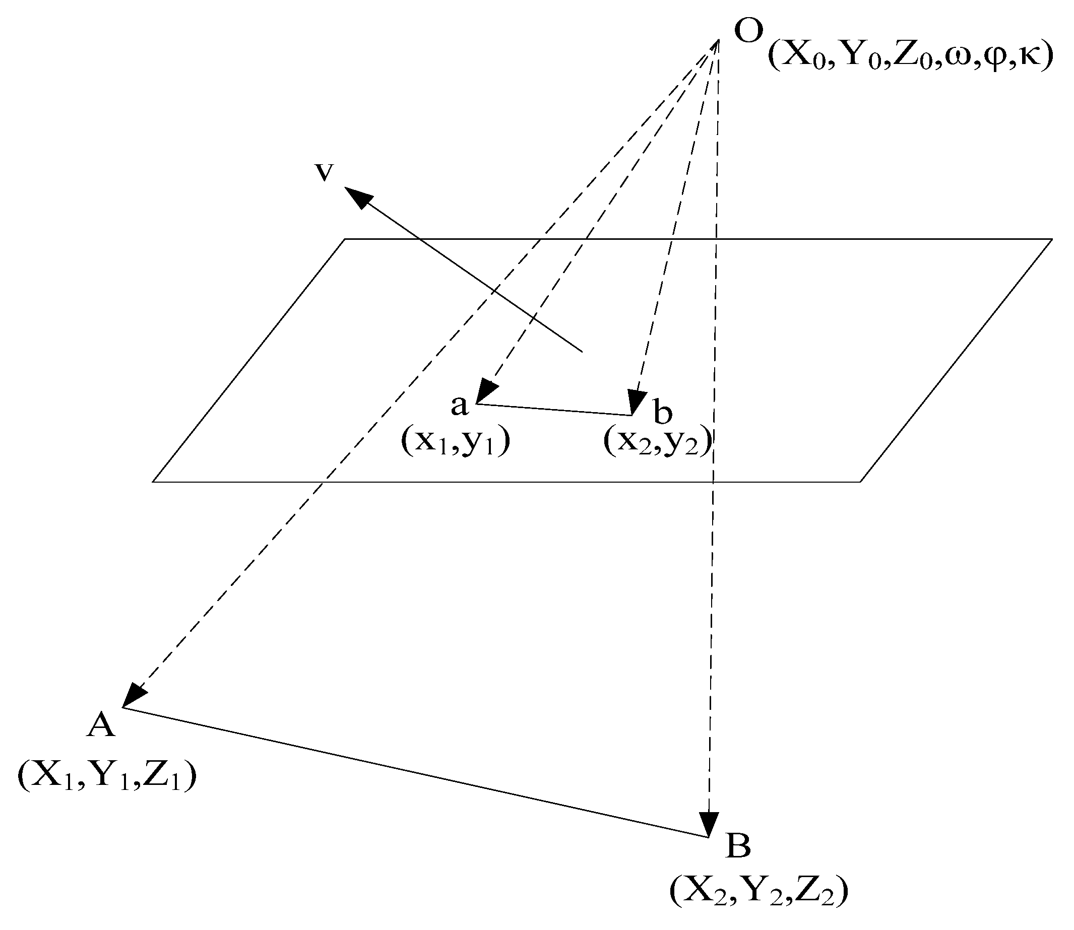
2.3. Coplanarity Constraint of the Linear Control Features
2.4. Block Bundle Adjustment
3. Study Area and Data Used

| Item | Value |
|---|---|
| Length (m) | 1.8 |
| Wingspan (m) | 2.6 |
| Payload (kg) | 4 |
| Take-off-weight (kg) | 14 |
| Endurance (h) | 1.8 |
| Flying height (m) | 300–6000 |
| Flying speed (km/h) | 80–120 |
| Power | Fuel |
| Flight mode | Manual, semi-autonomous, and autonomous |
| Launch | Catapult, runway |
| Landing | Sliding, parachute |
4. Experiments and Result Analysis
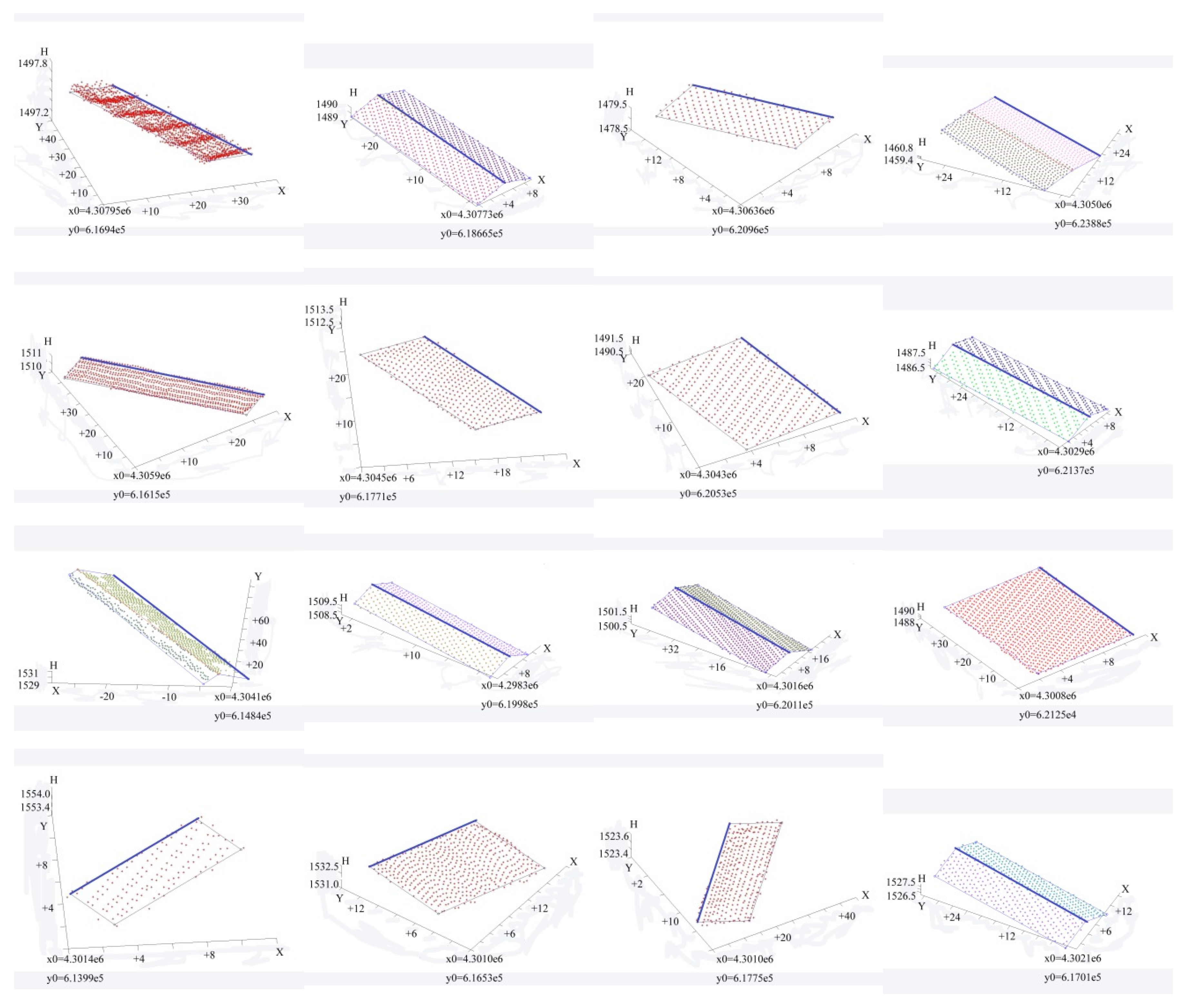
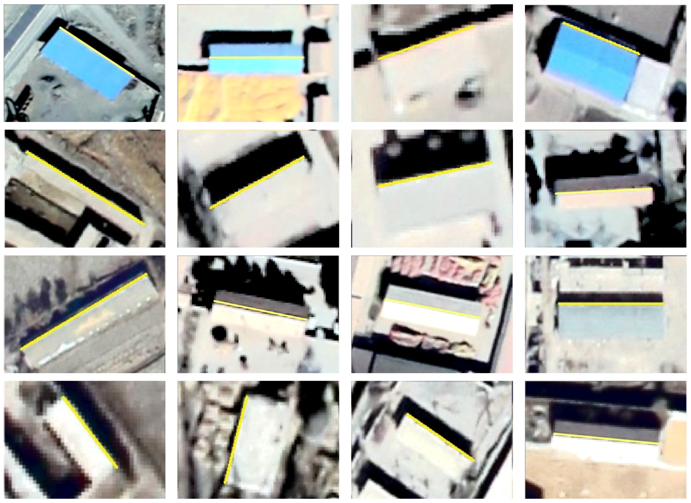
4.1. Linear Control Features and Tie Point Extraction Results
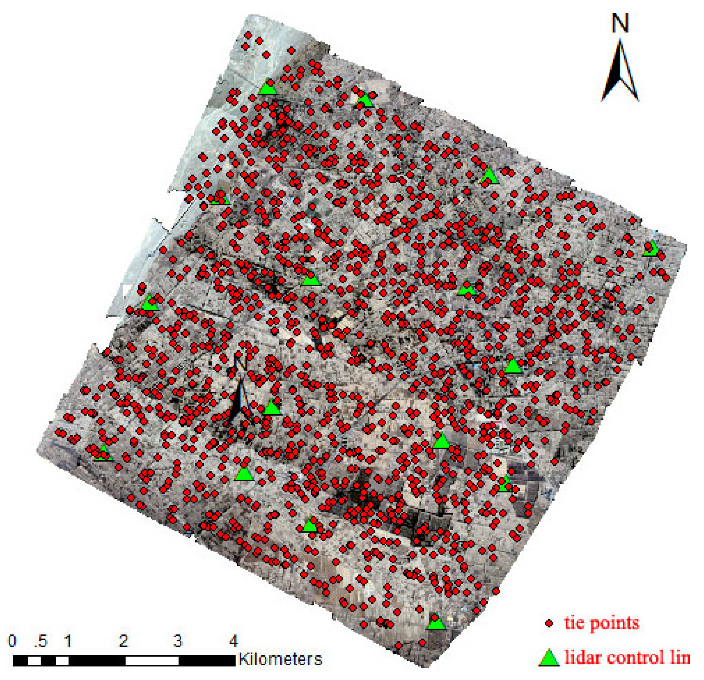
4.2. Registration Result
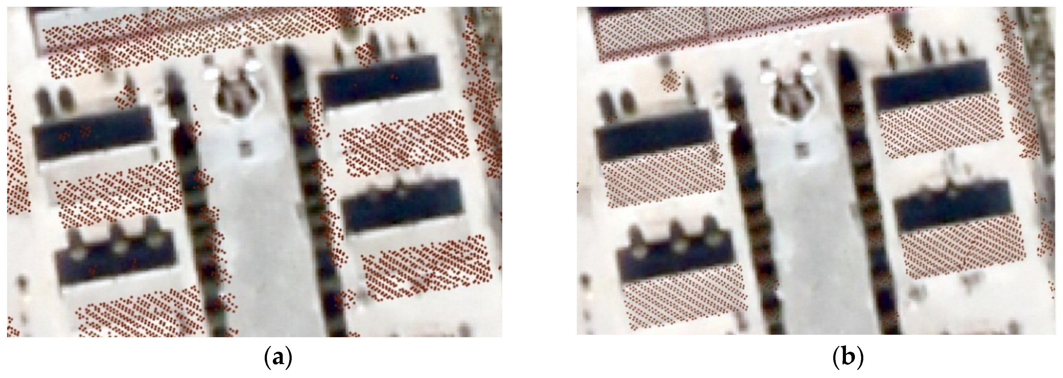
| Direct Georeferencing | Free Network Adjustment | Registration Based on Intensity Image (16 Control Points) | Registration Based on Intensity Image (32 Control Points) | Registration Based on Linear Features (16 Control Lines) | |
|---|---|---|---|---|---|
| Maximum | 602.10 | 58.75 | 6.09 | 6.09 | 1.90 |
| Average | 235.52 | 26.12 | 1.76 | 1.42 | 0.92 |
4.3. Comparison with Intensity Image Based Registration and Accuracy Evaluation
| Maximum Absolute Error | Root-Mean-Square Error | |||||
|---|---|---|---|---|---|---|
| X | Y | Z | X | Y | Z | |
| Direct georeferencing | 211.65 | 88.63 | 386.82 | 84.57 | 44.50 | 169.27 |
| Free network adjustment | 13.88 | 12.58 | 60.91 | 7.06 | 5.09 | 26.11 |
| Registration based on LiDAR intensity image (16 control points) | 1.38 | 1.64 | 4.59 | 0.67 | 0.61 | 1.98 |
| Registration based on LiDAR intensity image (32 control points) | 1.13 | 1.34 | 3.28 | 0.59 | 0.55 | 1.49 |
| Registration based on linear features (16 control lines) | 0.67 | 0.76 | 1.89 | 0.40 | 0.41 | 1.27 |
5. Conclusions
Acknowledgments
Author Contributions
Conflicts of Interest
References
- Eisenbeiss, H. UAV Photogrammetry; Institute of Geodesy and Photogrammetry, ETH Zurich: Zurich, Switzerland, 2009. [Google Scholar]
- Nagai, M.; Chen, T.; Shibasaki, R.; Kumagai, H.; Ahmed, A. UAV-borne 3-D mapping system by multisensor integration. IEEE Trans. Geosci. Remote Sens. 2009, 47, 701–708. [Google Scholar] [CrossRef]
- Berni, J.; Zarco-Tejada, P.J.; Suárez, L.; Fereres, E. Thermal and narrowband multispectral remote sensing for vegetation monitoring from an unmanned aerial vehicle. IEEE Trans. Geosci. Remote Sens. 2009, 47, 722–738. [Google Scholar] [CrossRef]
- Restas, A. Forest fire management supporting by UAV based air reconnaissance results of Szendro Fire Department, Hungary. In Proceedings of the International Symposium on Environment Identities and Mediterranean Area, Corte-Ajaccio, France, 10–13 July 2006; Volume 10, pp. 73–77.
- Wilkinson, B.E. The Design of Georeferencing Techniques for Unmanned Autonomous Aerial Vehicle Video for Use with Wildlife Inventory Surveys: A Case Study of the National Bison Range, Montana; University of Florida: Gainesville, FL, USA, 2007. [Google Scholar]
- Li, N.; Huang, X.; Zhang, F.; Wang, L. Registration of aerial imagery and LiDAR data in desert areas using the centroids of bushes as control information. Photogramm. Eng. Remote. Sens. 2013, 79, 743–752. [Google Scholar] [CrossRef]
- Cramer, M. Direct Geocoding-is Aerial Triangulation Obsolete? Fritsch, D., Spiller, R., Eds.; Wichmann Verlag: Heidelberg, Germany, 1999; pp. 59–70. [Google Scholar]
- Perry, J.H.; Mohamed, A.; El-Rahman, A.H.; Bowman, W.S.; Kaddoura, Y.O.; Watts, A.C. Precision directly georeferenced unmanned aerial remote sensing system: Performance evaluation. In Proceedings of the Institute of Navigation National Technical Meeting, San Diego, CA, USA, 28–30 January 2008; pp. 680–688.
- Ackermann, F. Airborne laser scanning—Present status and future expectations. ISPRS J. Photogramm. Remote Sens. 1999, 54, 64–67. [Google Scholar] [CrossRef]
- Wehr, A.; Lohr, U. Airborne laser scanning—An introduction and overview. ISPRS J. Photogramm. Remote Sens. 1999, 54, 68–82. [Google Scholar] [CrossRef]
- Baltsavias, E.P. A comparison between photogrammetry and laser scanning. ISPRS J. Photogramm. Remote Sens. 1999, 54, 83–94. [Google Scholar] [CrossRef]
- Ma, R. Building Model Reconstruction from LiDAR Data and Aerial Photographs. Ph.D. Thesis, The Ohio State University, Columbus, OH, USA, 2005. [Google Scholar]
- Liu, X.; Zhang, Z.; Peterson, J.; Chandra, S. LiDAR-derived high quality ground control information and DEM for image orthorectification. GeoInformatica 2007, 11, 37–53. [Google Scholar] [CrossRef]
- James, T.D.; Murray, T.; Barrand, N.E.; Barr, S.L. Extracting photogrammetric ground control from LiDAR DEMs for change detection. Photogramm. Rec. 2006, 21, 312–328. [Google Scholar] [CrossRef]
- Barrand, N.E.; Murray, T.; James, T.D.; Barr, S.L.; Mills, J.P. Optimizing photogrammetric DEMs for glacier volume change assessment using laser-scanning derived ground-control points. J. Glaciol. 2009, 55, 106–116. [Google Scholar] [CrossRef]
- Rottensteiner, F.; Jansa, J. Automatic extraction of building from LiDAR data and aerial images. Proc. Intern. ISPRS 2002, 34, 295–301. [Google Scholar]
- Cui, L.L.; Tang, P.; Zhao, Z.M. Study on object-oriented classification method by integrating various features. Remote Sens. 2006, 10, 104–110. [Google Scholar]
- Syed, S.; Dare, P.; Jones, S. Automatic classification of land cover features with high resolution imagery and LiDAR data: An object oriented approach. In Proceedings of the SSC 2005 Spatial Intelligence, Innovation and Praxis: The National Biennial Conference of the Spatial Sciences Institute, Melbourne, Australia, 14–16 September 2005.
- Park, J.Y.; Shrestha, R.L.; Carter, W.E.; Tuell, G.H. Land-cover classification using combined ALSM (LiDAR) and color digital photography. In Proceedings of the ASPRS Conference, St. Louis, MO, USA, 23–27 April 2001; pp. 23–27.
- Mastin, A.; Kepner, J.; Fisher, J. Automatic registration of LiDAR and optical images of urban scenes. Comput. Vis. Pattern Recognit. 2009. [Google Scholar] [CrossRef]
- Brenner, C. Building reconstruction from images and laser scanning. Int. J. Appl. Earth Obs. 2005, 6, 187–198. [Google Scholar] [CrossRef]
- Zhang, F.; Huang, X.F.; Li, D.R. A review of registration of laser scanner data and optical image. Bull. Surv. Mapp. 2008, 2, 004. [Google Scholar]
- Parmehr, E.G.; Fraser, C.S.; Zhang, C.; Leach, J. Automatic registration of optical imagery with 3D LiDAR data using statistical similarity. ISPRS J. Photogramm. Remote Sens. 2014, 88, 28–40. [Google Scholar] [CrossRef]
- Parmehr, E.G.; Zhang, C.; Fraser, C.S. Automatic registration of multi-source data using mutual information. ISPRS Ann. Photogramm. Remote Sens. Spat. Inf. Sci. 2012, 7, 301–308. [Google Scholar] [CrossRef]
- Zhao, W.; Nister, D.; Hsu, S. Alignment of continuous video onto 3D point clouds. IEEE Trans. Pattern Anal. Mach. Intell. 2005, 27, 1305–1318. [Google Scholar] [CrossRef] [PubMed]
- Rusinkiewicz, S.; Levoy, M. Efficient variants of the ICP algorithm. In Proceedings of the Third International Conference on 3-D Digital Imaging and Modeling, Quebec, QC, Canada, 28 May–1 June 2001; pp. 145–152.
- Habib, A.; Ghanma, M.; Morgan, M.; Al-Ruzouq, R. Photogrammetric and LiDAR data registration using linear features. Photogramm. Eng. Remote Sens. 2005, 71, 699–707. [Google Scholar] [CrossRef]
- Habib, A.F.; Shin, S.; Kim, C.; al-Durgham, M. Integration of photogrammetric and LiDAR data in a multi-primitive triangulation environment. In Innovations in 3D Geo Information Systems; Springer: Berlin, Germany; Heidelberg, Germany, 2006; pp. 29–45. [Google Scholar]
- Wong, A.; Orchard, J. Efficient FFT-accelerated approach to invariant optical–LiDAR registration. IEEE Trans. Geosci. Remote Sens. 2008, 46, 3917–3925. [Google Scholar] [CrossRef]
- Rönnholm, P.; Haggrén, H. Registration of laser scanning point clouds and aerial images using either artificial or natural tie features. ISPRS Ann. Photogramm. Remote Sens. Spatial Inf. Sci. 2012, 1–3, 63–68. [Google Scholar]
- Kwak, T.S.; Kim, Y.; Yu, K.Y.; Lee, B.K. Registration of aerial imagery and aerial LiDAR data using centroids of plane roof surfaces as control information. KSCE J. Civ. Eng. 2006, 10, 365–370. [Google Scholar] [CrossRef]
- Moravec, H.P. Rover visual obstacle avoidance. In Proceedings of the 7th International Joint Conference on Artificial Intelligence, Vancouver, BC, Canada, 24–28 August 1981; pp. 785–790.
- Förstner, W.; Gülch, E. A fast operator for detection and precise location of distinct points, corners and centres of circular features. In Proceedings of Intercommission Conference on Fast Processing of Photogrammetric Data, Interlaken, Switzerland, 2–4 June 1987; pp. 281–305.
- Smith, S.M.; Brady, J.M. SUSAN—A new approach to low level image processing. Int. J. Comput. Vis. 1997, 23, 45–78. [Google Scholar] [CrossRef]
- Harris, C.; Stephens, M. A combined corner and edge detector. In Proceedings of the 4th Alvey Vision Conference, Manchester, UK, 31 August–2 September 1988; pp. 147–151.
- Lowe, D.G. Object recognition from local scale-invariant features. In Proceedings of the IEEE International Conference on Computer Vision, Kerkyra, Greece, 20–27 September 1999; pp. 1150–1157.
- Canny, J. A computational approach to edge detection. IEEE Trans. Pattern Anal. Mach. Intell. 1986, 6, 679–698. [Google Scholar] [CrossRef]
- Kanopoulos, N.; Vasanthavada, N.; Baker, R.L. Design of an image edge detection filter using the Sobel operator. IEEE J. Solid State Circuits 1988, 23, 358–367. [Google Scholar] [CrossRef]
- Marr, D.; Hildreth, E. Theory of edge detection. Proc. R. Soc. Lond. Ser. B. Biol. Sci. 1980, 207, 187–217. [Google Scholar] [CrossRef]
- Habib, A.F.; Morgan, M.; Lee, Y.R. Bundle adjustment with self-calibration using straight lines. Photogramm. Rec. 2002, 17, 635–650. [Google Scholar] [CrossRef]
- Marcato, J.J.; Tommaselli, A. Exterior orientation of CBERS-2B imagery using multi-feature control and orbital data. ISPRS J. Photogramm. Remote Sens. 2013, 79, 219–225. [Google Scholar] [CrossRef]
- Tong, X.; Li, X.; Xu, X.; Xie, H.; Feng, T.; Sun, T.; Jin, Y.; Liu, X. A two-phase classification of urban vegetation using airborne LiDAR data and aerial photography. IEEE J. Sel. Topics Appl. Earth Obs. Remote Sens. 2014, 7, 4153–4166. [Google Scholar] [CrossRef]
- Axelsson, P. Processing of laser scanner data—Algorithms and applications. ISPRS J. Photogramm. Remote Sens. 1999, 54, 138–147. [Google Scholar]
- Axelsson, P. DEM generation from laser scanner data using adaptive TIN models. Int. Arch. Photogramm. Remote Sens. 2000, 33, 111–118. [Google Scholar]
- Forlani, G.; Nardinocchi, C. Building detection and roof extraction in laser scanning data. Int. Arch. Photogramm. Remote Sens. 2001, 34, 319–328. [Google Scholar]
- Borrmann, D.; Elseberg, J.; Lingemann, K.; Nuchter, A. The 3D hough transform for plane detection in point clouds: A Review and a new accumulator design. 3D Res. 2011, 2, 1–13. [Google Scholar] [CrossRef]
- Tarsha-Kurdi, F.; Landes, T.; Grussenmeyer, P. Hough-transform and extended RANSAC algorithms for automatic detection of 3d building roof planes from lidar data. Int. Arch. Photogramm. Remote Sens. Spat. Inf. Syst. 2007, 36, 407–412. [Google Scholar]
- Duda, R.O.; Hart, P.E. Use of the Hough transformation to detect lines and curves in pictures. Commun. ACM 1972, 15, 11–15. [Google Scholar] [CrossRef]
- Song, J.; Lyu, M.R. A Hough transform based line recognition method utilizing both parameter space and image space. Pattern Recognit. 2005, 38, 539–552. [Google Scholar] [CrossRef]
- Gruen, A. Adaptive least squares correlation: A powerful image matching technique. South Afr. J. Photogramm. Remote Sens. Cartogr. 1985, 14, 175–187. [Google Scholar]
- Tong, X.; Liu, X.; Chen, P.; Liu, S.; Luan, K.; Li, L.; Liu, S.; Liu, X.; Xie, H.; Jin, Y.; et al. Integration of UAV-based photogrammetry and terrestrial laser scanning for the three-dimensional mapping and monitoring of open-pit mine areas. Remote Sens. 2015, 7, 6635–6662. [Google Scholar] [CrossRef]
- Li, X.; Cheng, G.D.; Liu, S.M.; Xiao, Q.; Ma, M.; Jin, R.; Che, T.; Liu, Q.; Wang, W.; Qi, Y.; et al. Heihe Watershed Allied Telemetry Experimental Research (HiWATER): Scientific objectives and experimental design. Bull. Am. Meteorol. Soc. 2013, 94, 1145–1160. [Google Scholar] [CrossRef]
- Xiao, Q.; Wen, J.G. Hiwater: Airborne LiDAR Raw Data in the Middle Reaches of the Heihe River Basin; Institute of Remote Sensing and Digital Earth, Chinese Academy of Sciences: Beijing, China, 2014. [Google Scholar]
© 2016 by the authors; licensee MDPI, Basel, Switzerland. This article is an open access article distributed under the terms and conditions of the Creative Commons by Attribution (CC-BY) license (http://creativecommons.org/licenses/by/4.0/).
Share and Cite
Liu, S.; Tong, X.; Chen, J.; Liu, X.; Sun, W.; Xie, H.; Chen, P.; Jin, Y.; Ye, Z. A Linear Feature-Based Approach for the Registration of Unmanned Aerial Vehicle Remotely-Sensed Images and Airborne LiDAR Data. Remote Sens. 2016, 8, 82. https://doi.org/10.3390/rs8020082
Liu S, Tong X, Chen J, Liu X, Sun W, Xie H, Chen P, Jin Y, Ye Z. A Linear Feature-Based Approach for the Registration of Unmanned Aerial Vehicle Remotely-Sensed Images and Airborne LiDAR Data. Remote Sensing. 2016; 8(2):82. https://doi.org/10.3390/rs8020082
Chicago/Turabian StyleLiu, Shijie, Xiaohua Tong, Jie Chen, Xiangfeng Liu, Wenzheng Sun, Huan Xie, Peng Chen, Yanmin Jin, and Zhen Ye. 2016. "A Linear Feature-Based Approach for the Registration of Unmanned Aerial Vehicle Remotely-Sensed Images and Airborne LiDAR Data" Remote Sensing 8, no. 2: 82. https://doi.org/10.3390/rs8020082
APA StyleLiu, S., Tong, X., Chen, J., Liu, X., Sun, W., Xie, H., Chen, P., Jin, Y., & Ye, Z. (2016). A Linear Feature-Based Approach for the Registration of Unmanned Aerial Vehicle Remotely-Sensed Images and Airborne LiDAR Data. Remote Sensing, 8(2), 82. https://doi.org/10.3390/rs8020082


