Scanning, Multibeam, Single Photon Lidars for Rapid, Large Scale, High Resolution, Topographic and Bathymetric Mapping
Abstract
:1. Introduction
2. SPL Instrument Overview and Heritage
2.1. NASA “Microaltimeter”
2.2. Second Generation SPL (“Leafcutter”)
2.3. NASA Mini-ATM
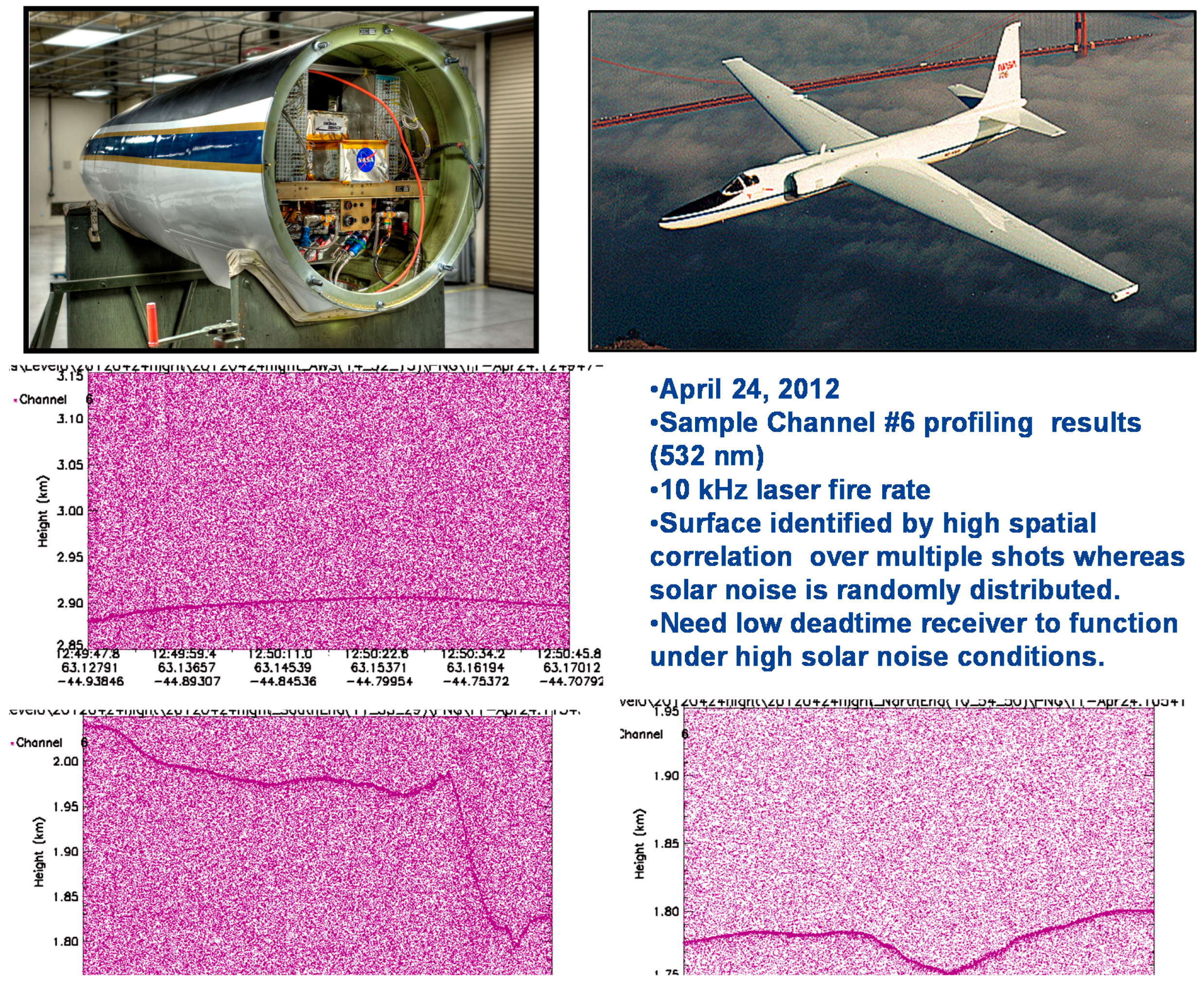
2.4. High Resolution Quantum Lidar System (HRQLS 1 and 2)
2.5. High Altitude Lidar (HAL)
2.6. NASA’s Multiple Altimeter Beam Experimental Lidar (MABEL)
2.7. Summary Table of Sigma Scanning Lidar Properties
3. Data Editing
4. Sample HRQLS-1 Data
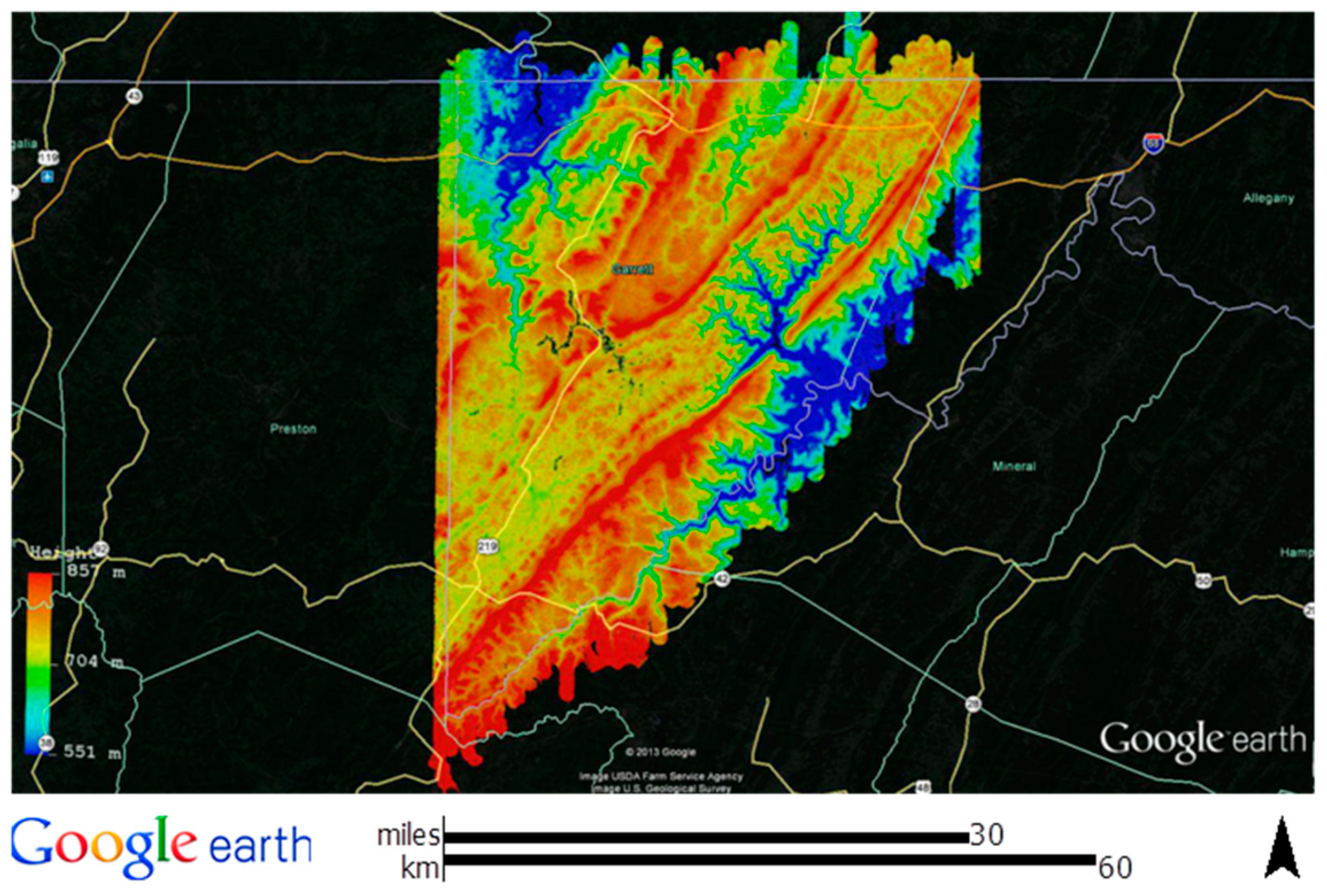
4.1. Garrett County, MD
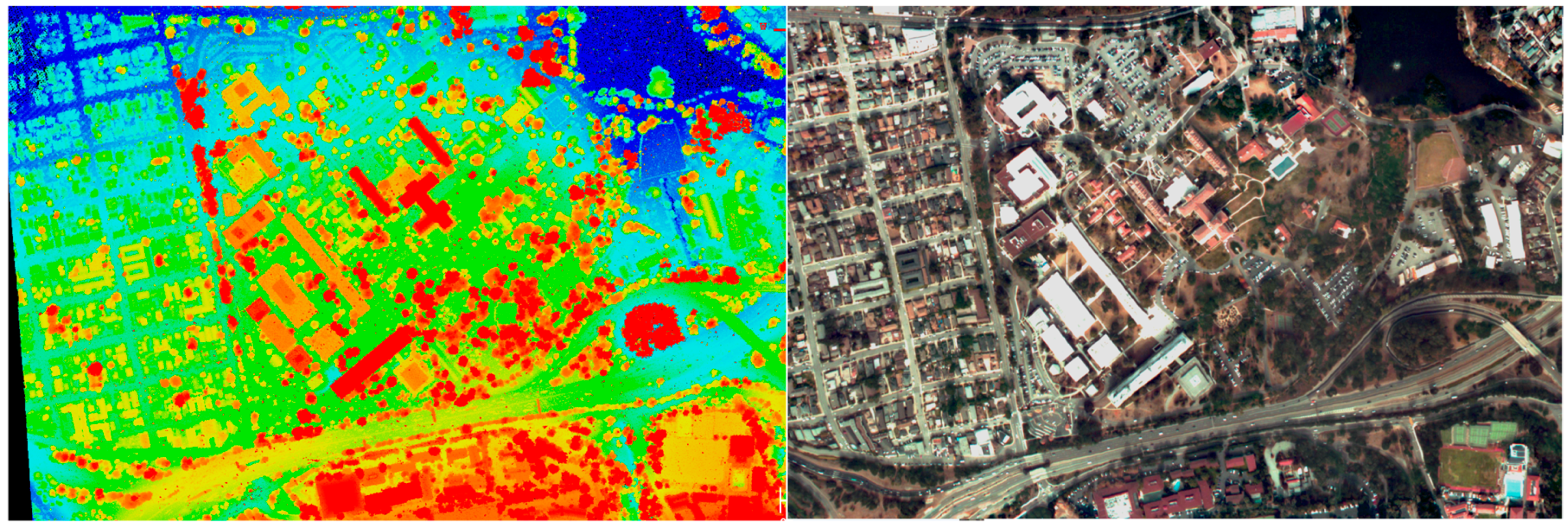
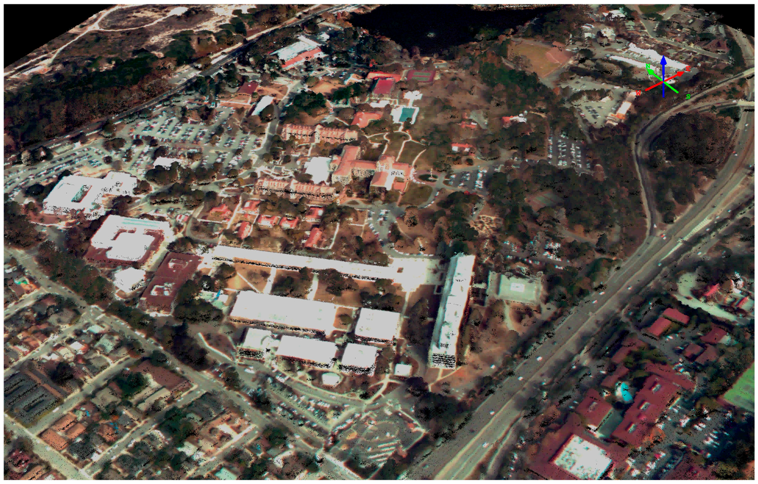
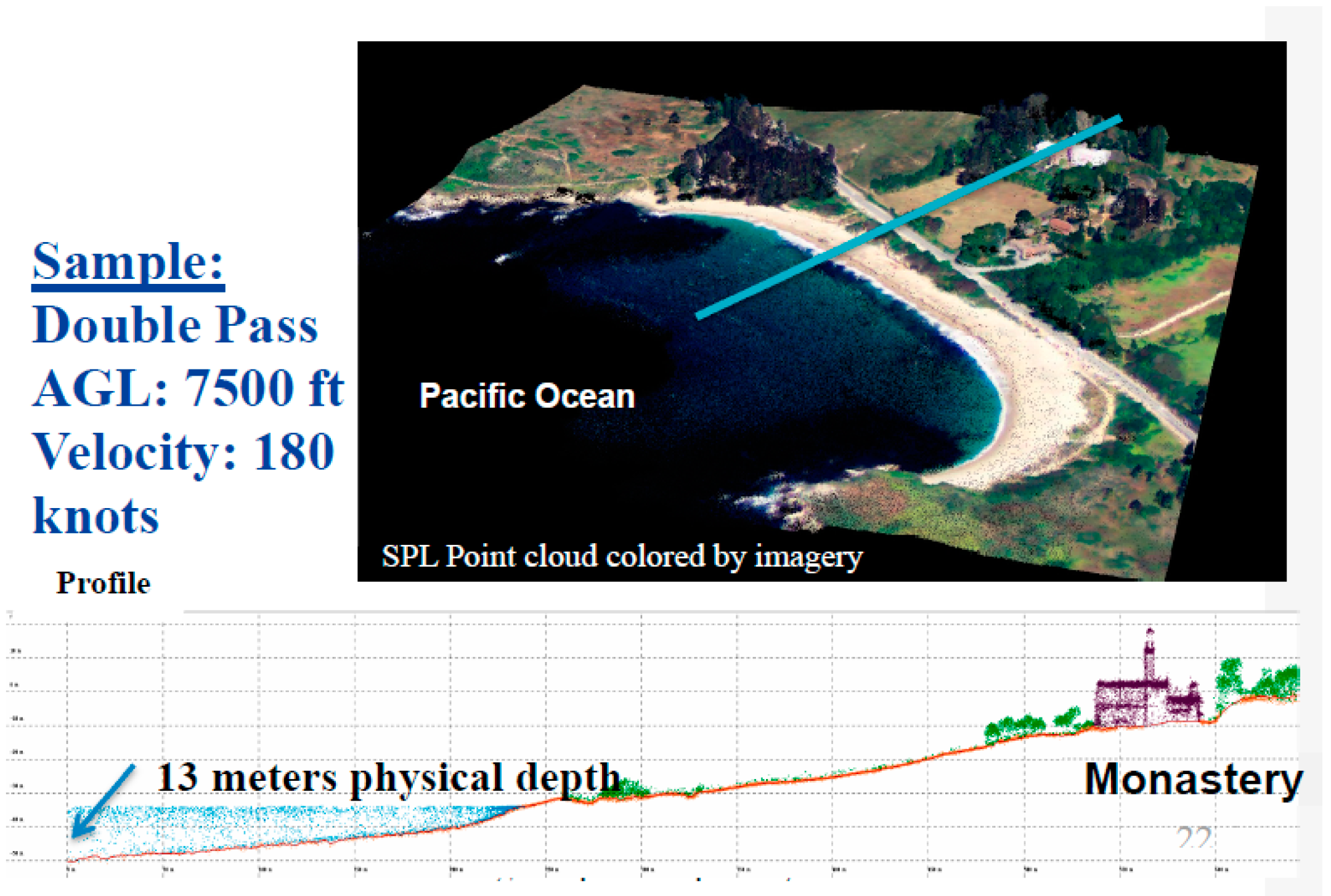
4.2. Monterey/Pt. Lobos, California
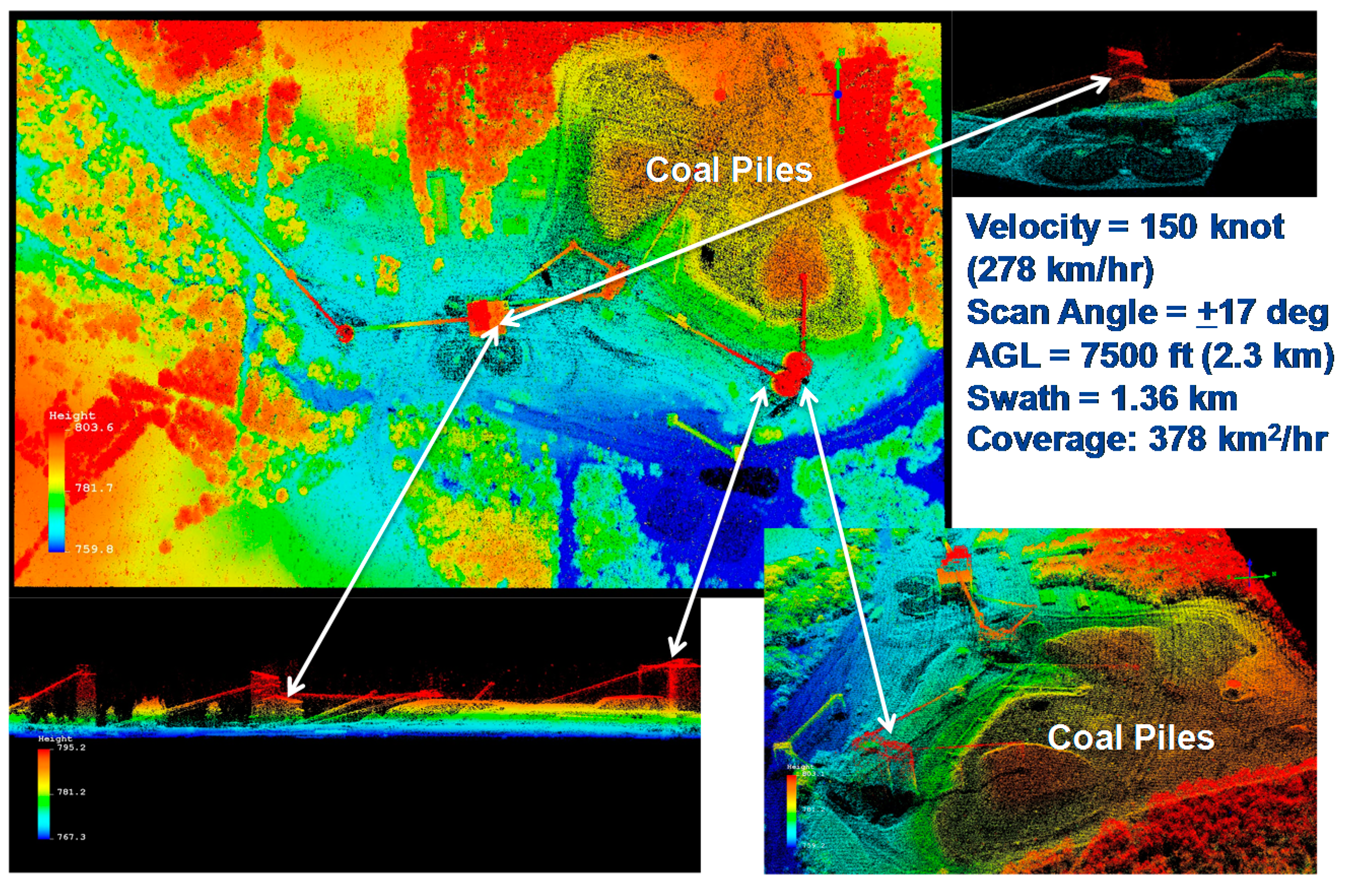
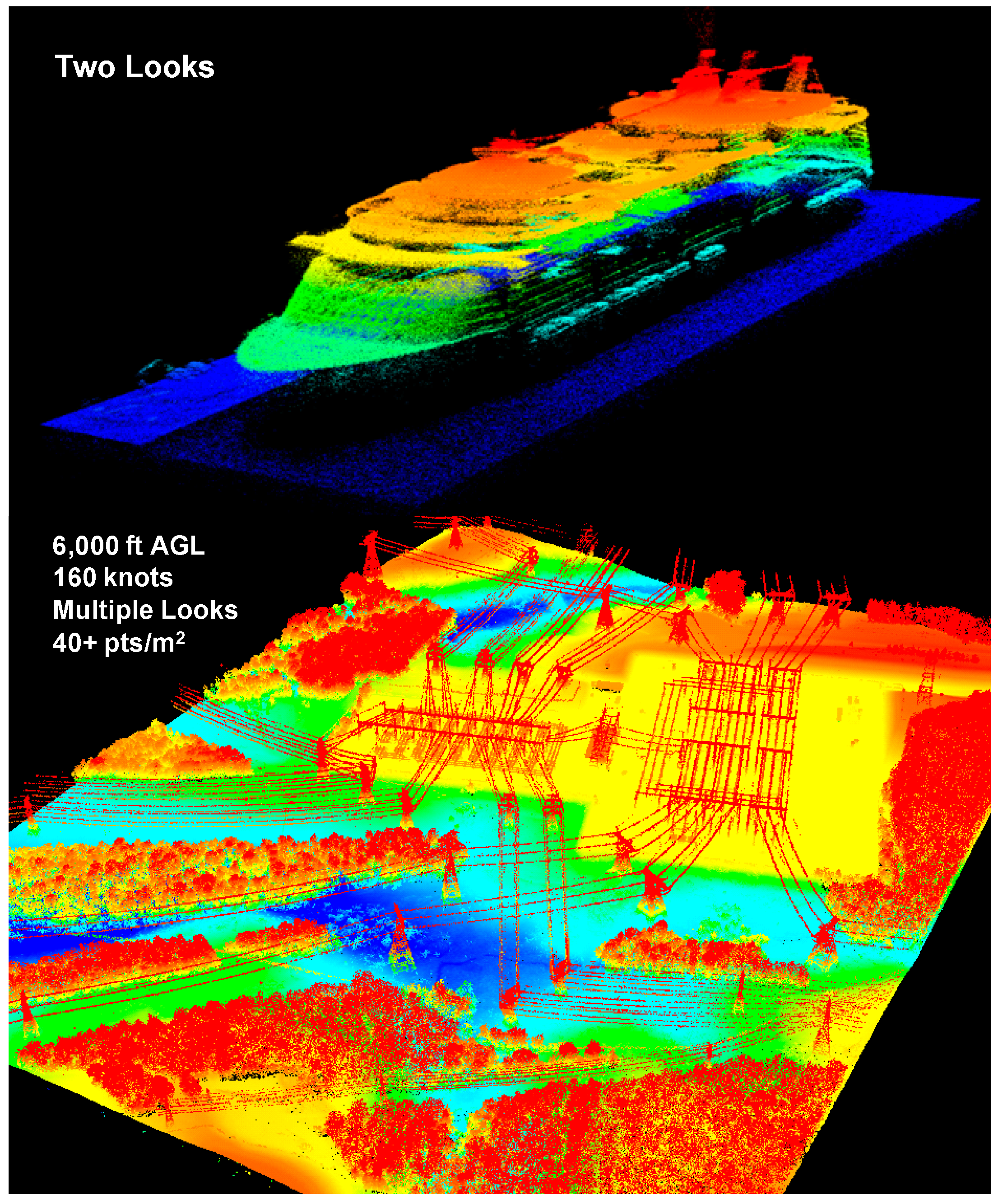
4.3. High Density Images
5. Single Photon Lidar (SPL) vs. Geiger Mode (GM) Lidar
5.1. Key Differences between SPL and GM Lidars
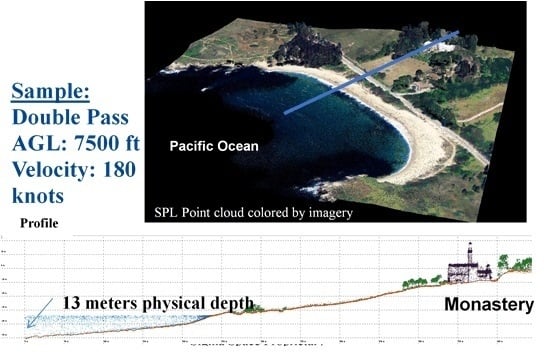
- Laser Wavelength: Current GM systems utilize the fundamental Nd:YAG wavelength at 1064 nm in the Near InfraRed (NIR) whereas Sigma SPLs use the frequency doubled green wavelength of Nd:YAG at 532 nm. The 1064 nm wavelength is sometimes touted as having several natural advantages including: (1) a factor of 3 lower solar background; (2) generally higher reflectances from natural surfaces such as soil/dry vegetation (25% vs. 15%) and green vegetation (65% vs. 10%); (3) slightly better atmospheric transmission; and (4) no frequency conversion losses in laser power which are typically on the order of 40% to 50% [2,15]. The 532 nm wavelength benefits from: (1) the availability of relatively mature and inexpensive, high efficiency array detectors and narrowband spectral filters; (2) detector dark count contributions to background noise are typically much lower in the visible spectrum; and (3) good transmission in water columns which allows solid land topography and bathymetry to be performed by a single instrument at a single wavelength as in Figure 13.
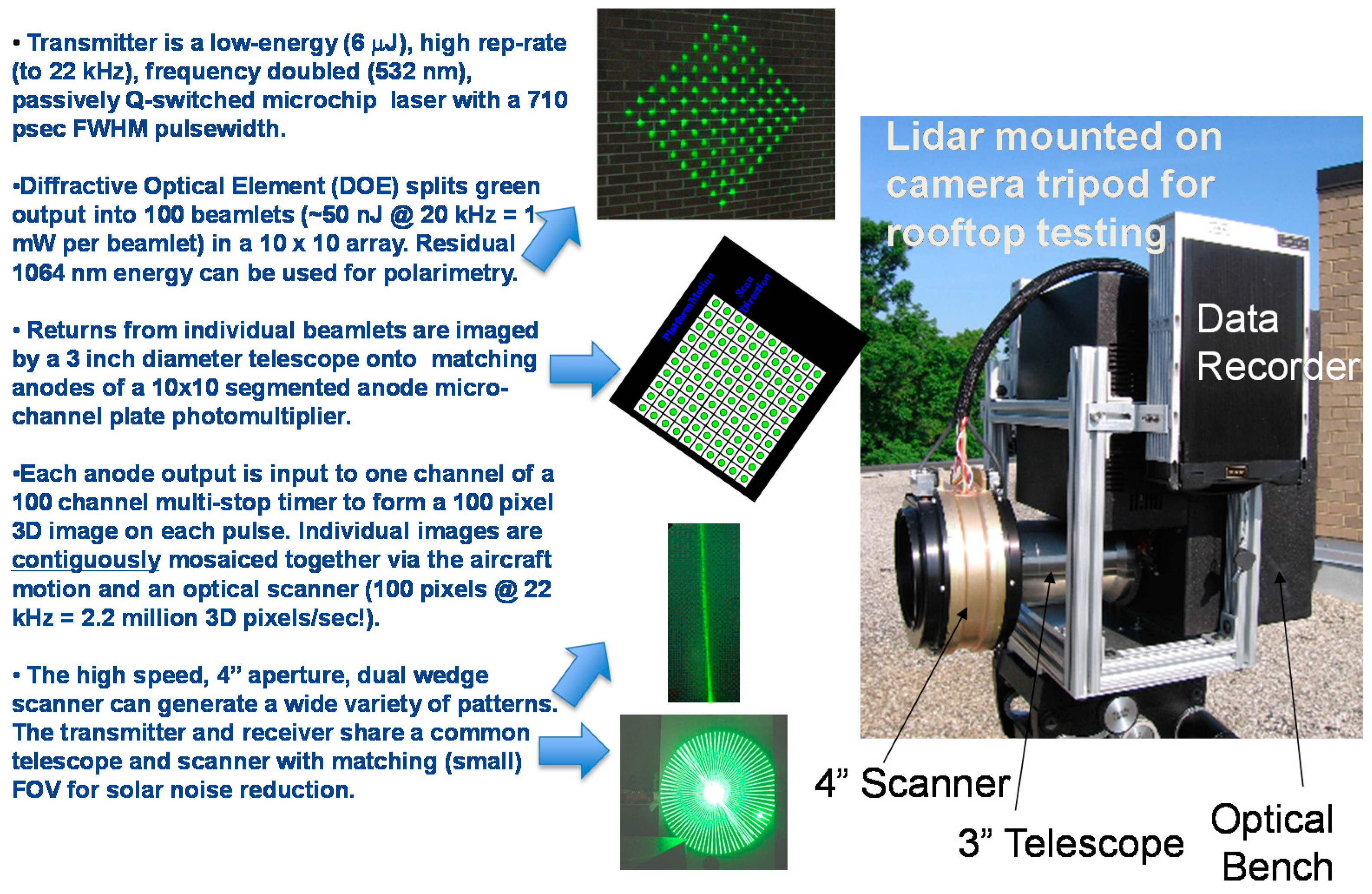
- Detector Array Size: Sigma SPLs use relatively inexpensive and compact COTS segmented anode microchannel plate photomultipliers which are currently available in 10 × 10 formats or 100 pixels per laser pulse. The Harris GM systems, on the other hand, currently utilize relatively expensive InP/InGaAsP SPAD 128 × 32 arrays/cameras containing 4096 pixels with on-chip readout rates in excess of 100 kHz [16]. In SPL systems, each pixel/anode essentially has a zero recovery time since each 1.6 mm × 1.6 mm pixel contains tens of thousands of microchannels, and therefore a single photon entering the photocathode activates a very small percentage of the available microchannels in the immediate vicinity of the photon strike. Thus, photons entering at slightly different spatial locations within the pixel experience the same amplification unless the microchannels become saturated, which generally has not been the case in field operations to date. In effect, a single SPL detector pixel behaves much like highly pixelated Geiger Mode array with the exception that all of the microchannel outputs are tied to a common anode and input to a common multistop timing channel capable of recording all of the photon events within the range gate and the pixel FOV. This limits the ground horizontal resolution to the FOV of the pixel which was 15 cm for Leafcutter and 50 cm square for the moderate to high altitude lidars. The current Sigma SPL receiver design typically accepts ten surface and/or noise events per pixel per pulse, but this is not a hard limitation. In effect, each SPL pixel acts as if it was a large array of individual GM SPADs covering the same FOV but tied to a common anode so that the timing of all photon events occurring within a given beamlet and pulse can be measured by a single, fast recovery, timing channel.
- Receiver Recovery Times: As just discussed, the SPL pixel recovery time of 1.6 nanoseconds (sometimes referred to as “deadtime” or “blanking loss” [15]) is limited not by the detector but by the timing receiver, whereas current GMAPD recovery times are typically in the range of 50 to 1600 nanoseconds depending on whether the Single Photon Avalanche Diodes (SPADs) making up the array are actively or passively quenched. This implies that SPLs can detect, within the same pixel, objects which are separated by only 0.24 m in range. In contrast, detected surfaces must be separated by 7.5 m or 240 m to be seen by an actively or passively quenched GMAPD respectively. Furthermore, each GMAPD in the array, as currently implemented in the Harris system, has only one measurement opportunity per imaging cycle although Harris claims that future asynchronous readout integrated circuits (ROICs) will enable multiple Time of Flight (TOF) measurements per APD per cycle [15]. While this would greatly enhance GM lidar performance, the detection rates within the small FOV of a given APD will still be limited by the longer quenching times.
5.2. Mapping Unobstructed Solid Surfaces in the Presence of Solar Noise
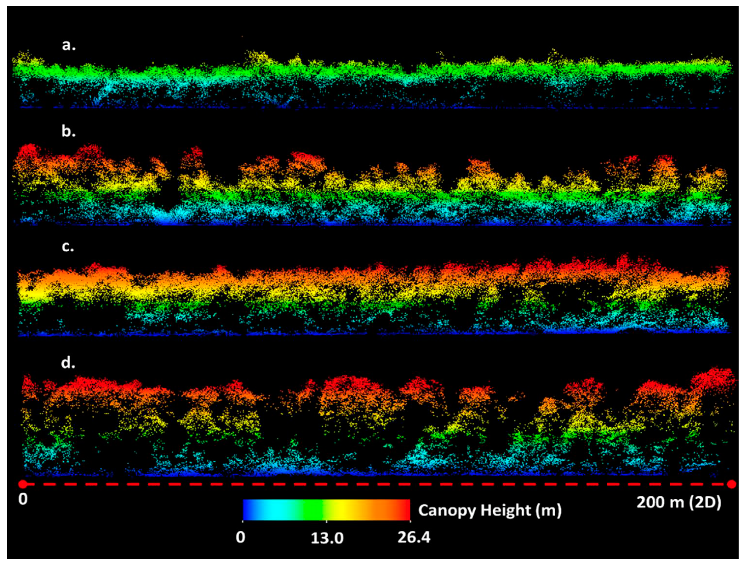
5.3. Viewing the Surface through Semi-Porous Obscurants Such as Tree Canopies
5.4. Brief Summary of the Theoretical Results
6. Summary
Acknowledgments
Conflicts of Interest
References
- Degnan, J.; McGarry, J.; Zagwodzki, T.; Dabney, P.; Geiger, J.; Chabot, R.; Steggerda, C.; Marzouk, J.; Chu, A. Design and performance of an airborne multikilohertz, photon-counting microlaser altimeter. Int. Arch. Photogramm. Remote Sens. 2001, XXXIV-3/W4, 9–16. [Google Scholar]
- Degnan, J. Photon-Counting Multikilohertz Microlaser Altimeters for Airborne and Spaceborne Topographic Measurements. J. Geodyn. 2002, 4, 503–549. [Google Scholar] [CrossRef]
- Harding, D. Pulsed Laser Altimeter Ranging Techniques and Implications for Terrain Mapping. In Topographic Laser Ranging and Scanning: Principles and Processing; Shan, J., Toth, C.K., Eds.; CRC Press: Boca Raton, FL, USA, 2009. [Google Scholar]
- Degnan, J.; Wells, D.; Machan, R.; Leventhal, E. Second Generation 3D Imaging Lidars based on Photon-Counting. In Proceedings of SPIE Optics East, Boston, MA, USA, 12 September 2007.
- Carter, W.; Shrestha, R.; Slatton, K. Photon counting airborne laser swath mapping (PC-ALSM). In Gravity, Geoid, and Space Missions; Jekeli, C., Bastos, L., Fernandez, J., Eds.; Springer: Berlin/Heidelberg, Germany, 2004; pp. 214–217. [Google Scholar]
- Cossio, T.; Slatton, C.; Carter, W.; Shrestha, K.; Harding, D. Predicting topographic and bathymetric measurement performance for low-SNR airborne lidar. IEEE Trans. Geosci. Remote Sens. 2009, 47, 2298–2315. [Google Scholar] [CrossRef]
- Degnan, J.J. A Conceptual Design for a Spaceborne 3D Imaging Lidar. E&I Electrotechnik und Informationstechnik (Austria) 2002, 4, 99–106. [Google Scholar]
- Gluckman, J. Design of the processing chain for a high-altitude, airborne, single photon lidar mapping instrument. Proc. SPIE 2016. [Google Scholar] [CrossRef]
- Abdalati, W.; Zwally, H.; Bindschadler, R.; Csatho, B.; Farrell, S.; Fricker, H.; Harding, D.; Kwok, R.; Lefsky, M.; Markus, T.; et al. The ICESat-2 laser altimetry mission. Proc. IEEE 2010, 98, 735–751. [Google Scholar] [CrossRef]
- McGill, M.; Markus, T.; Scott, V.S.; Neumann, T. The Multiple Altimeter Beam Experimental Lidar (MABEL): An Airborne Simulator for the ICESat-2 Mission. J. Atmos. Ocean. Technol. 2013, 30, 345–352. [Google Scholar] [CrossRef]
- Swatantran, A.; Tang, H.; Barrett, T.; DeCola, P.; Dubayah, R. Rapid, High-Resolution Forest Structure and Terrain Mapping over Large Areas using Single Photon Lidar. Sci. Rep. 2016. [Google Scholar] [CrossRef] [PubMed]
- Vaidyanathan, M.; Blask, S.; Higgins, T.; Clifton, W.; Davidsohn, D.; Carson, R.; Reynolds, V.; Pfannenstiel, J.; Cannata, R.; Marino, R.; et al. JIGSAW Phase III: A miniaturized airborne 3-D imaging laser radar with photon-counting sensitivity for foliage penetration. Proc. SPIE 2007. [Google Scholar] [CrossRef]
- Knowlton, R. Airborne Ladar Imaging Testbed; Tech Notes; MIT Lincoln Laboratory: Lexington, MA, USA, 2011; Available online: http://www.princetonlightwave.com/products/geiger-mode-cameras/ (accessed on 17 November 2016).
- Gray, G. High Altitude Lidar Operations Experiment (HALOE)—Part 1, System Design and Operation. In Proceedings of the Military Sensing Symposium, Active Electro-Optic Systems, Paper AH03, San Diego, CA, USA, 12–14 September 2011.
- Clifton, W.; Steele, B.; Nelson, G.; Truscott, A.; Itzler, M.; Entwhistle, M. Medium altitude airborne Geiger-mode mapping Lidar system. Proc. SPIE 2015, 9465, 946506. [Google Scholar] [CrossRef]
- Falcon IR Camera. Available online: http://www.princetonlightwave.com/products/geiger-mode-cameras/ (accessed on 17 November 2016).
- Harris Corporation. Available online: http://www.apsg.info/resources/Documents/Presentations/APSG34/IntelliEarth_Presentation_APSG34_Oct_2015.pdf (accessed on 14 November 2016).
- Higgins, S. Single Photon and Geiger Mode vs. Linear Mode Lidar. SPAR 3D. 2016. Available online: http://www.spar3d.com/news/lidar/single-photon-and-geiger-mode-vs-linear-mode-lidar/ (accessed on 14 November 2016).
- Li, Q.; Degnan, J.; Barrett, T.; Shan, J. First Evaluation on Single Photon-Sensitive Lidar Data. Photogramm. Eng. Remote Sens. 2016, 82, 455–463. [Google Scholar] [CrossRef]
- Abdullah, Q. A Star is Born: The State of New Lidar Technologies. Photogramm. Eng. Remote Sens. 2016, 82, 307–312. [Google Scholar] [CrossRef]
- Higgins, S. Single Photon Lidar Proven for Forest Mapping. SPAR 3D. 2016. Available online: http://www.spar3d.com/news/lidar/single-photon-lidar-proven-forest-mapping/ (accessed on 14 November 2016).
- Field, C. Sigma Space Corporation, Lanham, MD, USA. Private communication, 2014. [Google Scholar]
- Machan, R. Sigma Space Corporation, Lanham, MD, USA. Private communication, 2016. [Google Scholar]
- Degnan, J. Rapid, Globally Contiguous, High Resolution 3D Topographic Mapping of Planetary Moons Using a Scanning, Photon-Counting Lidar. International Workshop on Instrumentation for Planetary Missions, GSFC. 2012. Available online: http://www.lpi.usra.edu/meetings/ipm2012/pdf/1086.pdf (accessed on 14 November 2016).



| Low Altitude SPLs | Medium Altitude SPLs | High Altitude SPLs | |||
|---|---|---|---|---|---|
| Instrument Name | USAF “Leafcutter” | NASA Mini-ATM | HRQLS-1 | HRQLS-2 | HAL |
| Prototype Completion Dates | 2007 | 2010 | 2013 | 2016 | 2012 |
| Units/Customers | 2/USAF & Univ. of Texas | 1/NASA | 1/Sigma | 6/Sigma | 3/DoD |
| Primary Application | Military Prototype & Antarctic Cryosphere | Greenland Cryosphere | Civilian Surveying and mapping, Biomass Measurement, Bathymetry, Military Surveillance | Military Surveillance | |
| Design Platform | Aerostar Mini-UAV | Viking 300 UAV | King Air | King Air | Various |
| # beams/pixels, Np | 100/100 | 100/25 | 100/100 | 100/100 | |
| Wavelength | 532 nm | 532 nm | 532 nm | ||
| Laser Repetition Rate, fqs | 22 kHz | 25 kHz | 60 kHz | 32 kHz | |
| Laser Pulse Width (FWHM) | 0.7 ns | 0.7 ns | 0.5 ns | 0.1 ns | |
| Laser Output Power | 0.14 W | 1.7 W | 5 W | 15 W | |
| Maximum Measurements/s | 2,200,000 | 550,000 | 2,500,000 | 6,000,000 | 3,200,000 |
| Multiple Return Capability | Yes | Yes | Yes | ||
| Pixel Recovery Time | 1.6 ns | 1.6 ns | 1.6 ns | ||
| RMS Range Precision | 5 cm | 5.7 cm | 4.8 cm | 3.6 cm | |
| Telescope Diameter | 7.5 cm | 7.5 cm | 14 cm | 14 cm | |
| # Scanner Wedges | 2 | DOE | 2 | 1 Wedge or DOE | 1 Wedge |
| Scan Width (FOV) | Variable 0° to 28° | Fixed 90° cone | Variable 0° to 40° | 20°, 30°, 40° or 60° | Fixed 18° |
| Nominal A/C Velocity, vg | 161 km/h | 104 km/h | 370 km/h | 370 km/h | |
| Design AGL | 1 km | 2.5 km | 2.3 km | 3.4 km | 7.6 km |
| Nominal AGL Range, h | 1.0 to 2.5 km | 0.55 to 3 km | 2 to 3 km | 3 to 5.5 km | 6 to 11 km |
| Swath, S | 0.0015 to 1.247 km | 1.1 to 6 km | 0.005 to 2.184 km | 1.058 to 6.351 km | 1.901 to 3.484 km |
| Areal Coverage, Svl | 0.242 to 201 km2/h | 114 to 624 km2/h | 2 to 808 km2/h | 391 to 2350 km2/h | 703 to 1289 km2/h |
| Mean Measurement Attempts per m2 per pass, Dm | 39 to 32,795/m2 | 3 to 17/m2 | 11 to 4865/m2 | 9 to 55/m2 | 9 to 16/m2 |
| # of Modules | 2 | 1 | 1 (rack-mounted) | 1 (rack mounted) 1 (pod mounted) | |
| Instrument Volume/Dimensions | 0.071 m3 | 0.027 m3 Quasi-cube (0.3 m) | 0.26 m3 48 × 64 × 84 cm3 | 0.139 m3 82.5 × 48.25 × 35 cm3 | 0.52 m3 49 × 64 × 163 cm3 |
| Weight | 33 kg | 13 kg | 57 kg | 68 kg (sensor head) 22 kg (e-rack) | 113 kg (est.) |
| Prime Power (28VDC) | 266 W | ~168 W | 555 W | 700 W | <900 W (est) |
| Status | 2 Delivered | 1 Delivered | 1 Operational | 2 Operational, 4 in fab | 2 Delivered, 1 in fab |
© 2016 by the author; licensee MDPI, Basel, Switzerland. This article is an open access article distributed under the terms and conditions of the Creative Commons Attribution (CC-BY) license (http://creativecommons.org/licenses/by/4.0/).
Share and Cite
Degnan, J.J. Scanning, Multibeam, Single Photon Lidars for Rapid, Large Scale, High Resolution, Topographic and Bathymetric Mapping. Remote Sens. 2016, 8, 958. https://doi.org/10.3390/rs8110958
Degnan JJ. Scanning, Multibeam, Single Photon Lidars for Rapid, Large Scale, High Resolution, Topographic and Bathymetric Mapping. Remote Sensing. 2016; 8(11):958. https://doi.org/10.3390/rs8110958
Chicago/Turabian StyleDegnan, John J. 2016. "Scanning, Multibeam, Single Photon Lidars for Rapid, Large Scale, High Resolution, Topographic and Bathymetric Mapping" Remote Sensing 8, no. 11: 958. https://doi.org/10.3390/rs8110958
APA StyleDegnan, J. J. (2016). Scanning, Multibeam, Single Photon Lidars for Rapid, Large Scale, High Resolution, Topographic and Bathymetric Mapping. Remote Sensing, 8(11), 958. https://doi.org/10.3390/rs8110958


