Article

The Effect of Topography on Target Decomposition of Polarimetric SAR Data

Department of Geoinformation Engineering, Sejong University, 209 Neungdong-ro, Gwangjin-gu, Seoul 143-747, Korea
Remote Sens. 2015, 7(5), 4997-5011; https://doi.org/10.3390/rs70504997
Submission received: 4 March 2015 / Revised: 10 April 2015 / Accepted: 15 April 2015 / Published: 23 April 2015

Abstract

:
Polarimetric target decomposition enables the interpretation of radar images more easily, mostly based on physical assumptions, i.e., fitting physically-based scattering models to the polarimetric SAR observations. However, the model-fitting result cannot be always successful. Particularly, the performance of model-fitting in sloping forests is still an open question. In this study, the effect of ground topography on the model-fitting-based polarimetric decomposition techniques is investigated. The estimation accuracy of each scattering component in the decomposition results are evaluated based on the simulated target matrix by using the incoherent vegetation scattering model that accounts for the tilted scattering surface beneath the forest canopy. Experimental results show that the surface and the double-bounce scattering components can be significantly misestimated due to the topographic slope, even when the volume scattering power is successfully estimated.

Graphical Abstract

1. Introduction

In the field of remote sensing, utilization of microwave frequency with synthetic aperture radar (SAR) has many operational advantages in monitoring the Earth’s surface with its high-resolution, day and night imaging capability. In particular, there is a rapidly increasing interest in the application of radar polarimetry due to increasing availability of space-borne polarimetric SAR (POLSAR) systems. Fully polarimetric SAR data provide a possibility to separate scattering contributions of different natures, which can be associated with certain elementary scattering mechanisms. This specific polarimetric data processing, named the polarimetric target decomposition, enables interpretation of radar images more easily and, thus, has been an active topic for about two decades. This is mostly based on eigenvalue-eigenvector analysis [1,2,3] or on physical assumptions, i.e., fitting physically-based scattering models to the polarimetric SAR observations [4,5,6,7].
Eigenvalue-eigenvector-based decomposition is a rigorous mathematical technique leading to an understanding of averaged scattering mechanisms without symmetry constraints. However, it is not physically based, and the interpretation of the results is not easy, especially for multiple or volume scattering problems in vegetation.
On the other hand, the physical model-fitting approach, which is the main focus of this study, is based on the physics of radar scattering and has the advantage in that it can provide useful information for distinguishing between different surface cover types. However, there have been open issues, such as overestimation of the volume scattering component and negative power problems, in the model-fitting-based decomposition techniques. Particularly, the performance of model-fitting cannot be always successful, especially in non-orthogonally-oriented man-made structures with respect to the line of sight and sloping mountainous forests. There have been several efforts to extend model-fitting approaches for discriminating a wide class of man-made structures [8,9,10]. On the other hand, the performance of model-fitting in sloping forests is still an open question.
In mountainous forests, local topographic variations can lead to changes in the microwave scattering mechanisms [11,12,13]. Particularly, it has been reported that, among the radar backscattered signals, direct ground and vegetation-ground interactions can be significantly affected by the presence of topography [13]. Consequently, the validity of the scattering models used in the target decomposition and relating slope-induced errors in the output of target decomposition techniques should be carefully evaluated in sloping forest areas.
It is not easy to address this issue, however, with SAR observations, since the SAR system measures the total backscattered signal, which is a mixture of waves scattered from elementary vegetation structures. In this study, the effect of topographic slope variations on the model-fitting-based target decomposition method is evaluated on the basis of the simulated target matrix by the microwave vegetation scattering model proposed in [13]. In the following section, a brief review of the target decomposition methods is presented. The description of the vegetation scattering model for sloping terrain and simulated datasets used for this paper are given in Section 3. The effect of local topography on the performance of target decomposition methods is also discussed in Section 3. Finally, a summary and concluding remarks are presented in Section 4.

2. Model-Fitting-Based POLSAR Decomposition

The model-fitting-based decomposition technique aims to separate the POLSAR observation matrix as a linear combination of elementary scattering matrices related to specific scattering models. Among several approaches, four widely-used methods are recalled in this study, such as the Freeman–Durden decomposition (FDD) [4], the Yamaguchi decomposition (YD) [5], the Yamaguchi decomposition with orientation compensation (YDR) [6] and the non-negative eigenvalue decomposition (NNED) [7].
In the FDD method, which is one of the pioneering works in the model-fitting approach, the coherency matrix [T] can be decomposed into three scattering types: surface, double-bounce and volume scattering, such as:
[ T ] = f s [ 1 b * 0 b | b | 2 0 0 0 0 ] + f d [ | a | 2 a 0 a * 1 0 0 0 0 ] + f v 1 4 [ 2 0 0 0 1 0 0 0 1 ]
where f s , f d and f v are surface, double-bounce and volume scatter contributions to the backscatter and a and b are unknown double-bound and surface scattering coefficients to be determined from the measured coherency matrix, respectively. The scattering powers P s , P d and P v , corresponding to surface, double-bounce and volume scattering, respectively, are determined by:
P s   =   f s ( 1 + | b | 2 ) ; P d   =   f d ( 1 + | a | 2 ) , and   P v   =   f v .
This method was developed based on several assumptions: (1) the observed coherency matrix satisfies reflection symmetry; (2) the volume scattering can be modeled as a cloud of randomly-oriented dipoles; and (3) the cross-polarization scattering component can only be generated by the volume scattering mechanism. Consequently, the model-fitting with the FDD method will be problematic when the studied targets do not meet those assumptions. In the development of the target decomposition method, much effort has been devoted to broadening the range of validity over the FDD method.
Yamaguchi et al. [5] extended the FDD method by adding a non-reflection-symmetric scattering component, such as:
[ T ] = f s [ T s ] + f d [ T d ] + f v [ T v ] + f c [ T c ]
where the additional fourth component   [ T c ] is the helix scattering model given by:
[ T c ] = 1 2 [ 0 0 0 0 1 ± j 0 j 1 ]
Furthermore, the YD method takes into account a more general volume scattering model than the original uniform distribution model in the FDD. Although the YD method improved the range of validity, the assumptions in model-fitting still do not hold for some targets, e.g., rough surfaces, sloping grounds and oriented buildings, resulting in a negative power problem in the surface or double-bounce scattering component.
Yamaguchi et al. [6] further improved the four-component decomposition approach by taking into account orientation angle compensation. Problems in the reflection symmetry assumption can be often found in the targets having a tilted local coordinate with respect to the radar coordinate, resulting in the polarimetric orientation angle shift. The orientation angle shift in the measured coherency matrix can be compensated by the rotation of an orientation angle, which is equivalent to the rotation of the coherency matrix by an angle minimizing the T 33 component [6], given as follows:
[ T ˜ ] = [ U ] [ T ] [ U T ] , with [ U ] = [ 1 0 0 0 cos 2 ψ sin 2 ψ 0 sin 2 ψ cos 2 ψ ]
where [ T ˜ ] and [ T ] are coherency matrices after and before rotation, respectively, and [ U ] is a unitary rotation operator. The orientation angle ψ can be obtained from POLSAR data as follows:
4 ψ = t a n 1 { 2 Re ( T 23 ) T 22 T 33 }
The span and T 11 terms are invariant by the unitary transformation. However, the compensation reduces the cross-polarization power T 33 and makes the T 23 term become purely imaginary. Consequently, orientation angle compensation applied to the YD can further improve the range of validity of model-fitting-based decomposition. However, the unitary transformation cannot compensate changes in physical scattering mechanisms of tilted targets, and the YDR method cannot completely remove negative powers.
Van Zyl et al. [7] proposed another approach to resolve the negative power problem. Instead of improving modelization, the NNED method addresses this issue by taking into account non-negative constraint in the inversion results. Since all cross-polarization power is attributed to volume scattering in the model-fitting assumptions, the volume scattering component can be firstly obtained from measured cross-polarization power in the inversion process. Then, other components can be computed from the remaining matrix, such as:
[ T ] f v [ T v ] = f s [ T s ] + f d [ T d ] .
The basic idea of the NNED method is that the remaining matrix must be positive semidefinite to represent physically-realizable scatterers. Consequently, the volume scattering power is estimated under the constraint of the non-negative eigenvalue. Based on the reflection symmetry assumption, the NNED method computes the maximum volume scattering power allowed that makes all three eigenvalues of [ T ] f v [ T v ] greater than or equal to zero. According to the nonnegative eigenvalue constraint, the negative power problem can be avoided. However, since the scattering models to fit POLSAR data remain the same, shifts of f v from its original values in the FDD rather indicate potential flaws in scattering models. The ranges of validity and topography-induced errors of the FDD, YD, YDR and NNED methods in sloping forests areas will be examined in the following section.

3. Experimental Results

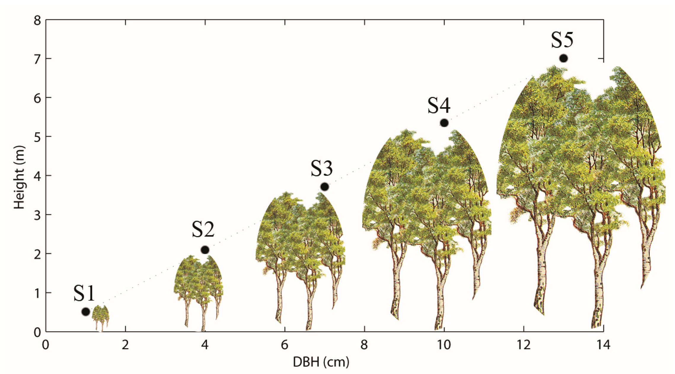
3.1. Simulation of Polarimetric Scattering from Mountainous Forests

The experimental analysis of topography effects on the target decomposition methods is carried out by using the simulated coherency matrix obtained from vegetation scattering model of sloping terrain [13]. This vegetation scattering model is based on the first-order solution of the radiative transfer model and considers a tilted scattering surface beneath forest canopy. It takes into account three characteristic scattering phenomena of sloping forests areas: (1) the local incidence angle embedded in ground-related scattering contributions; (2) the local coordinate shift of slanted ground plane, both in the forward and backward scattering components; and (3) the change of the path length through the canopy.
For simulations of polarimetric backscattering, deciduous-type trees with five different size categories (S1–S5) are considered (Figure 1) in this study to evaluate target decomposition methods with respect to variations of scattering mechanisms according to forest biomass. Tree diameters at breast height (DBH) of each size category are: S1 = 1 cm, S2 = 4 cm, S3 = 7 cm, S4 = 10 cm and S5 = 13 cm.
Tree heights are: S1 = 0.5 m, S2 = 2.1 m, S3 = 3.7 m, S4 = 5.3 m and S5 = 7 m. The tree canopy is represented in terms of a crown layer and a trunk layer and is described as a layered random medium comprising leaves, stems, primary branches, secondary branches and trunk. Trunks and branches are modeled as cylinders, leaves as circular discs and stems as needles. Densities, dimensions and orientation distributions for each layer are specified as summarized in Table 1. The orientation of vegetation constituents is characterized by the Eulerian polar angle [13]. It is assumed to be uniformly distributed within the angular boundaries listed in Table 1. The soil backscatter property is modeled using the small perturbation method [14]. The dielectric properties of the vegetation constituents and soil surface are set to be 30-j5 and 15-j1.5, respectively. The simulation was performed at L-band frequency (1.24 GHz) and an incidence angle of 45°. Radar backscattering mechanisms up to the first order solution of the vegetation scattering model are composed of ground backscatter ( [ T G ] ), trunk-ground interaction ( [ T T G ] ), crown-ground interaction ( [ T C G ] ) and direct crown backscatter ( [ T C ] ). In this study, the simulated crown-ground and trunk-ground interaction terms are grouped as the vegetation-ground double-bounce scattering [ T V G ] .
Figure 1. Schematics of five types of vegetation for simulation of polarimetric parameters.
Remotesensing 07 04997 g001
Table 1. Parameters for modeling vegetation scattering.
ParametersCrown LayerTrunk Layer
LeafStemBranch 2Branch 1Trunk
Radius (cm)S150.10.120.310.5
S250.10.311.082.0
S350.10.461.793.5
S450.10.592.465.0
S550.10.713.116.5
½Length (cm)S10.010.511.355.010.0
S20.012.095.5821.042.0
S30.013.719.9037.074.0
S40.015.3514.2654.0107.0
S50.017.0018.6970.0140.0
Orientation (°)70–900–9015–800–400–10
Density (number/m3)2001004.50.350.01
Height (m)S10.30.2
S21.30.8
S32.21.5
S43.22.1
S54.22.8

3.2. Topography Effects on Model-Fitting-Based Decomposition

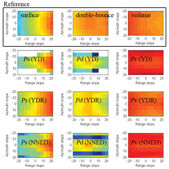
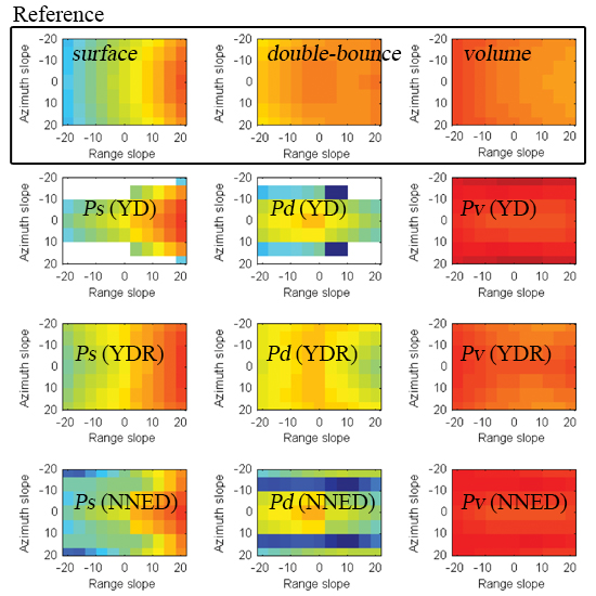
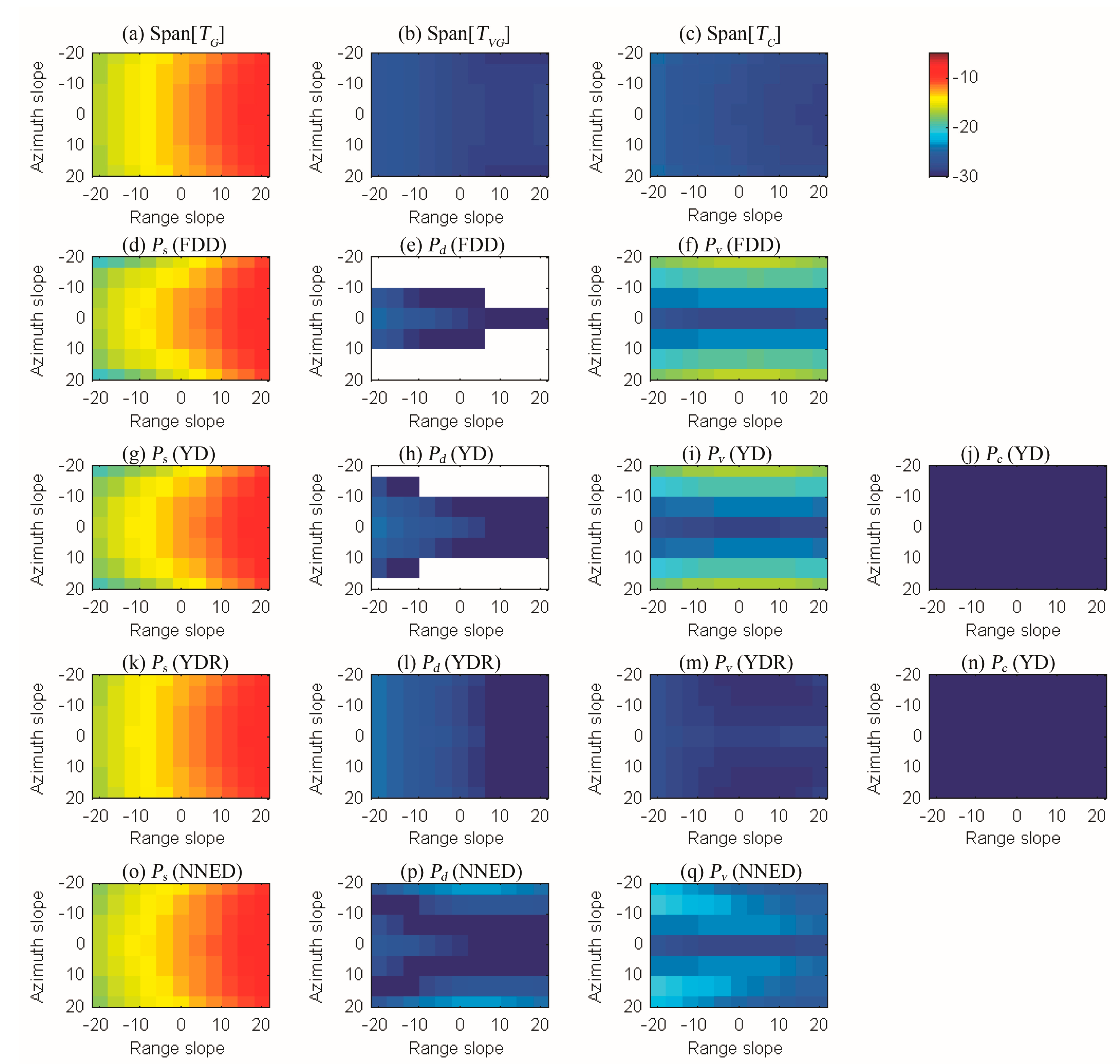
3.2.1. Changes of Scattering Mechanisms in Sloping Terrain

The simulation of the coherency matrix is carried out for variations of range and azimuth slopes ranging from −20° to 20°. Positive values of the range slope indicate tilts of the ground surface toward the radar, i.e., local incidence angles smaller than those of flat surface. Figure 2, Figure 3 and Figure 4 show changes in the scattering mechanisms with respect to the terrain range and azimuth slopes for S1, S3 and S5, respectively. The first row shows the reference scattering mechanism of the simulated coherency matrix. The second, third, fourth and fifth rows show model-fitting results derived from FDD, YD, YDR and NNED, respectively. The white-colored patches in the plot represent inversions with negative powers.
In the case of very small trees (S1), direct ground scattering is the dominant scattering mechanism among received signals, as shown in the first row of Figure 2, and it is highly affected by the range slope due to the sensitivity of surface scattering to the local incidence angle. The FDD method applied to the simulated coherency matrix exhibits significant overestimation of the volume scattering power as the azimuth slope increases, and negative power problems in the double-bounce scattering component can be identified as shown in the second row of Figure 2. Since the ground scattering component is visualized in the cross-polarization backscatter according to the local orientation sift, the third assumption of the FDD method no longer holds, resulting in an erroneous decomposition result. The YD method can slightly reduce the negative problem, but the volume scattering is still significantly overestimated in the YD method. The polarimetric orientation angle directly corresponds to the terrain orientation angle when the ground scattering mechanism dominates the radar backscattered signal, like the S1 case. Consequently, as shown in the fourth row of Figure 2, orientation angle compensation can mitigate this problem, and the model-fitting results by the YDR method are generally in good agreement with the true scattering mechanisms. The NNED method can also mitigate negative power problems in the double-bounce scattering component. However, there still exists the overestimation of the scattering contribution from the tree crown.
In the case of medium-sized trees (S3), the vegetation-ground double-bounce and the crown scattering contributions increase, and there is no single dominant scattering component among the three main scattering mechanisms, as shown in the first row of Figure 3. Similar to the S1 case, the FDD and YD methods provide significant overestimation of the volume scattering component as the azimuth slope increases. This causes inaccurate estimation in both the surface and the double-bounce scattering component, including negative powers. The third row of Figure 3 shows that orientation angle compensation mitigates the negative power problems. However, erroneous estimation in the double-bounce scattering component still remains in the YDR method. The NNED method can also resolve negative power problems, but less accurately estimates the surface and the double-bounce scattering components than those from the YDR method.
Figure 2. Changes in the scattering mechanisms with respect to the terrain range and azimuth slopes for S1. (ac) Reference scattering mechanisms (ground, vegetation-ground and canopy scattering, respectively) of the simulated coherency matrix. (df) Calculated scattering components from the Freeman–Durden decomposition (FDD) method. (gj) Calculated scattering components from the Yamaguchi decomposition (YD) method. (kn) Calculated scattering components from the Yamaguchi decomposition with orientation compensation (YDR) method. (oq) Calculated scattering components from the non-negative eigenvalue decomposition (NNED) method.
Remotesensing 07 04997 g002
Figure 3. Changes in the scattering mechanisms with respect to the terrain range and azimuth slopes for S3. (ac) Reference scattering mechanisms (ground, vegetation-ground and canopy scattering, respectively) of the simulated coherency matrix. (df) Calculated scattering components from the FDD method. (gj) Calculated scattering components from the YD method. (kn) Calculated scattering components from the YDR method. (oq) Calculated scattering components from the NNED method.
Remotesensing 07 04997 g003
The direct crown scattering becomes the dominant scattering mechanism in the case of large trees (S5), and both the ground scattering and the vegetation-ground interactions are highly affected by the ground topography, as shown in the first row of Figure 4. Errors in the model-fitting results from the FDD and YD methods increase both in range and azimuth slope directions in the presence of dense forests. The orientation angle compensation cannot resolve negative power problems in this case of large trees, and erroneous decomposition results still remain in the YDR method as the range and azimuth slope increase. The decomposition results from the NNED method exhibit better estimation of the volume scattering than other methods, while the estimation of surface and double-bounce scattering components are not very successful.
Figure 4. Changes in the scattering mechanisms with respect to the terrain range and azimuth slopes for S5. (ac) Reference scattering mechanisms (ground, double-bounce and canopy scattering, respectively) of the simulated coherency matrix. (df) Calculated scattering components from the FDD method. (gj) Calculated scattering components from the YD method. (kn) Calculated scattering components from the YDR method. (oq) Calculated scattering components from the NNED method.
Remotesensing 07 04997 g004

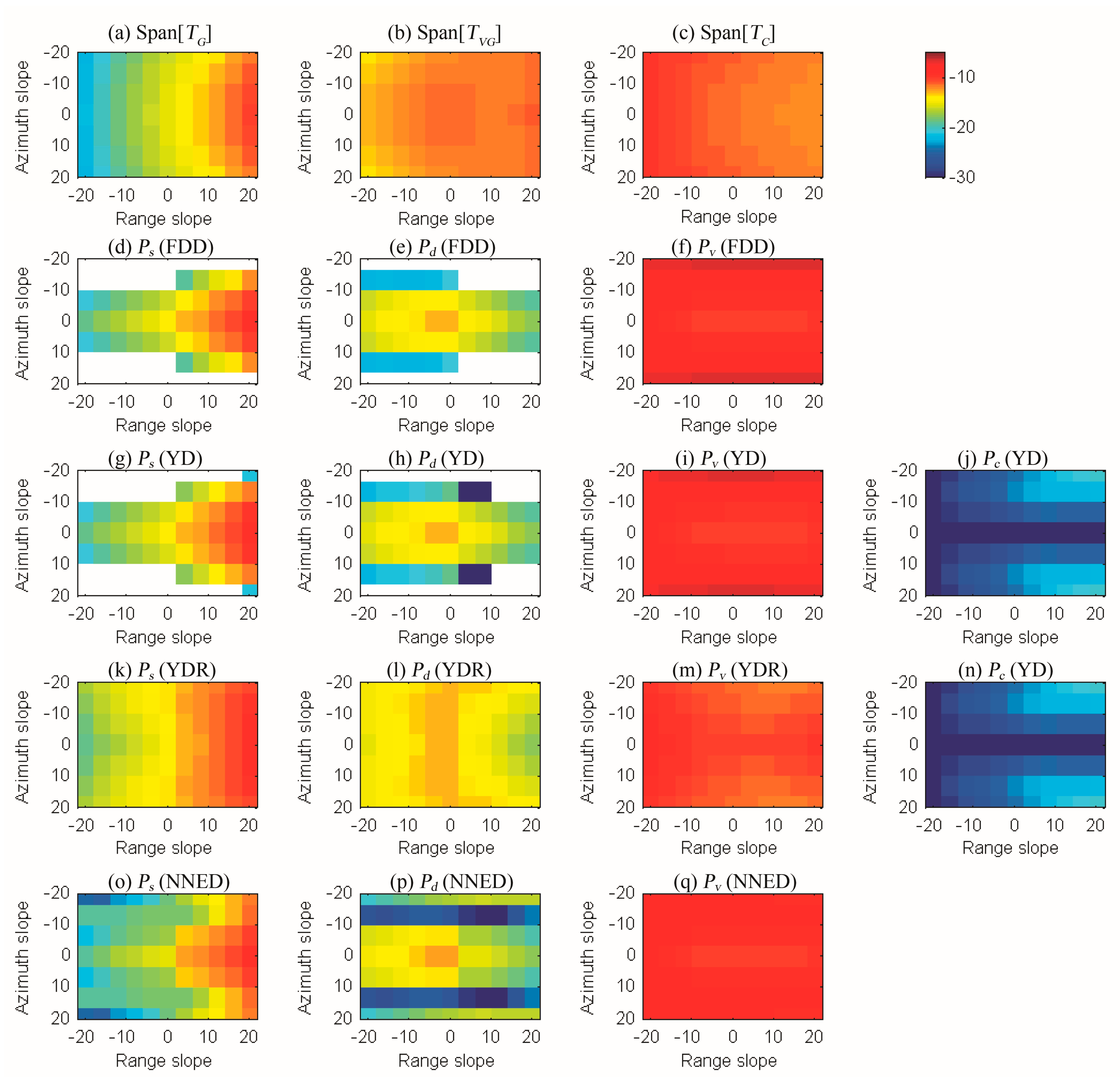
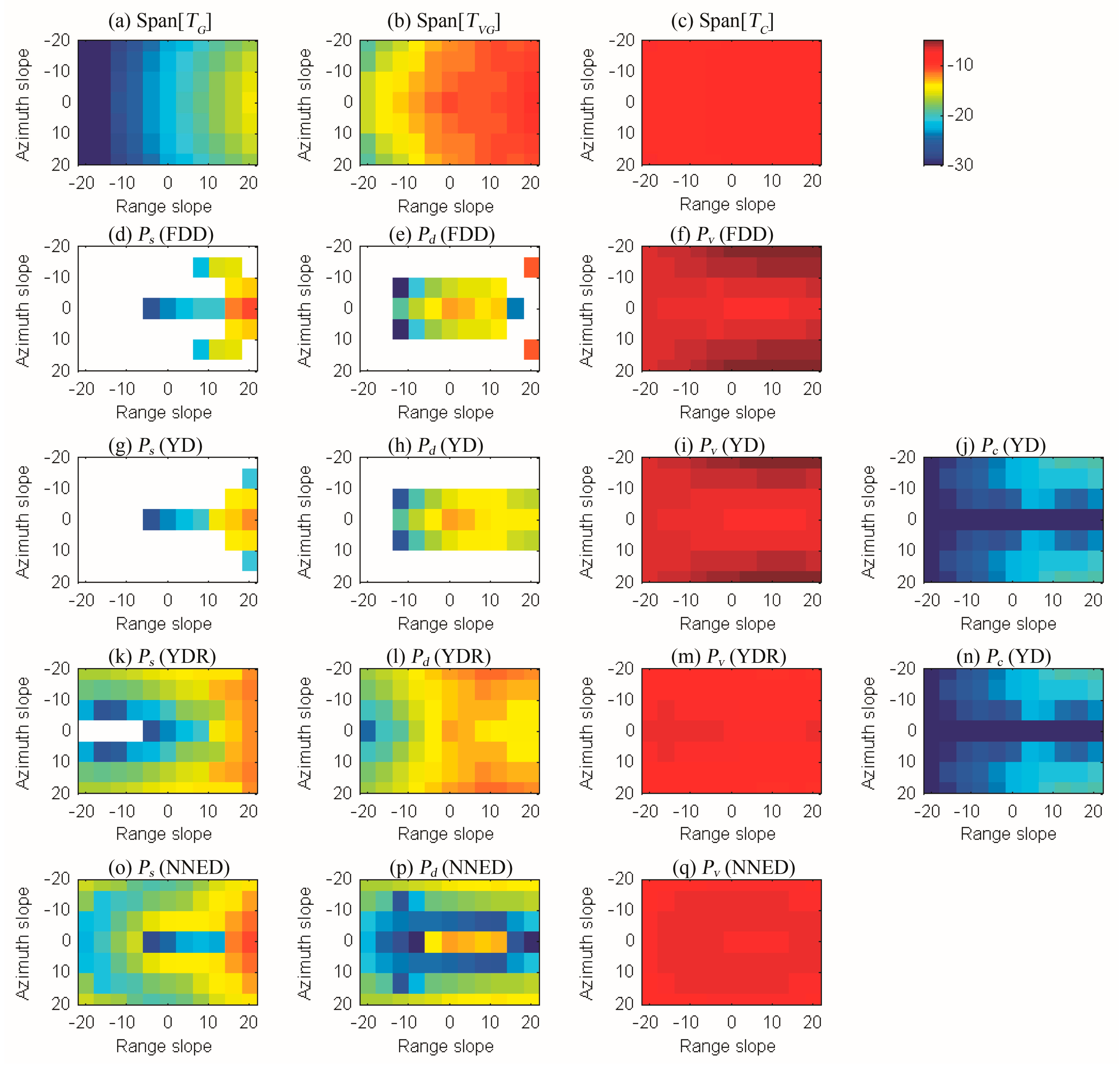
3.2.2. Effect of Range Slope on Decomposition Results
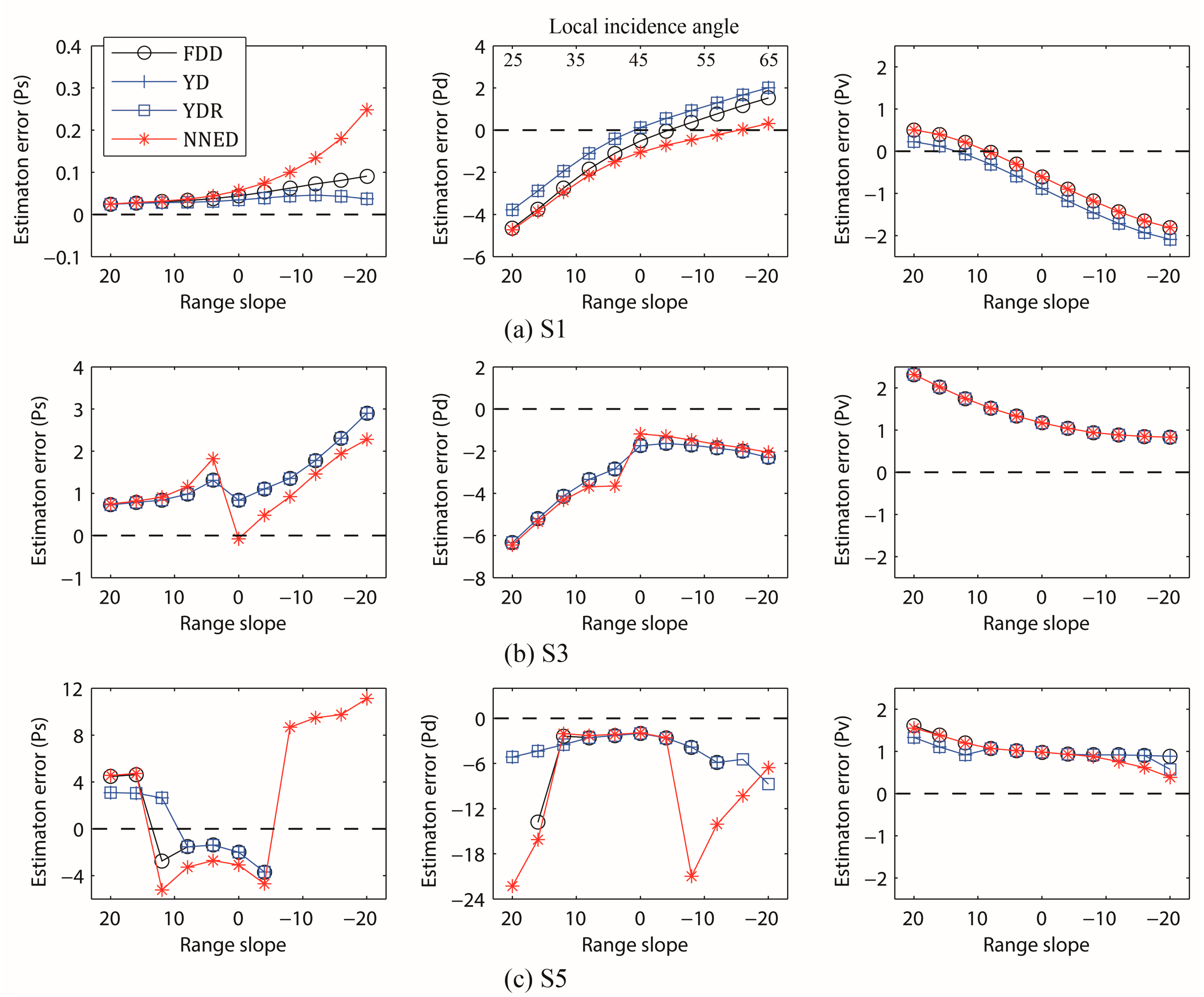
In this part, range-slope-induced errors in the output of target decomposition techniques are firstly assessed for quantitative evaluation of the model-fitting results. Thereafter, in Section 3.2.3, the azimuth slope effect on performance of model-fitting results will be evaluated. The estimation error is defined as:
e ^ ( i ) = P ^ x ( i ) P x r e f ( i )
where P ^ x , x = s , d , v is the span of calculated scattering component (in dB) by the model-fitting-based decomposition and P x r e f is the span of each scattering mechanism (in dB) in the simulated coherency matrix.
Figure 5. Estimation errors (in dB) of model-fitting-based decomposition methods with respect to the range slope angle. The first, second and third row are errors for three different size categories: (a) S1, (b) S3, and (c) S5.
Remotesensing 07 04997 g005
Figure 5 shows the estimation errors in each decomposition method with respect to the range slope of the ground plane, where the azimuth slope angle is fixed to be zero. The first, second and third rows are errors for three different size categories (S1, S3 and S5). The estimation of the volume scattering component by the model-fitting-based decomposition is affected by the range slope variation, as shown in the third column of Figure 5. In general, it is overestimated (up to 2 dB) as the local incidence angle decreases. The range-slope-induced error in the estimation of volume scattering then affects retrievals of surface and double-bounce scattering components. The estimation errors of those scattering components are further increased with an increase of the range slope angle. The model-fitting-based decomposition methods overestimate surface scattering, whereas they underestimate the double-bounce scattering as the range slope increases. On the other hand, the estimation error shows a different angular trend in the case of small trees (S1). The estimation errors of the surface scattering component, which is the dominant scattering mechanism, are very low (less than 0.3 dB) for all methods. However, the double-bounce scattering is underestimated in the front-slope, while being overestimated in the back-slope.
Table 2 summarizes the rang-slope-induced errors of each model-fitting-based decomposition result in terms of root-mean-square errors (RMSE), which are defined as RMSE = 1 / n i e ^ ( i ) 2 ). Here, scattering components having negative powers are adjusted to be 10 6 to prevent RMSE values of negative infinity.
Table 2. RMSE of each decomposition method for the range slope variation. Shaded cells represent that a range profile of the calculated scattering component contains negative power.
S1S2S3S4S5
FDDYDYDRNNEDFDDYDYDRNNEDFDDYDYDRNNEDFDDYDYDRNNEDFDDYDYDRNNED
P s 0.060.040.040.110.730.730.730.841.511.511.511.3110.1310.1010.103.4419.0218.9718.976.77
P d 2.191.851.852.232.492.492.492.633.373.373.373.464.393.033.037.4524.9219.384.6211.94
P v 1.011.201.201.011.211.211.211.211.421.421.421.421.211.111.111.211.101.010.991.03
When the ground scattering contribution is relatively high in backscatter signals, vegetation types S1–S3, there are not so many differences among the four decomposition methods in the range-slope-induced errors. In this case, the estimation of the double-bounce scattering component shows the worst accuracy, which has more than twice the RMSE of the volume scattering component. If the vegetation-related scattering contributions increase (S4 and S5), the estimation of the surface scattering becomes problematic as the local incidence angle increases, such as significant estimation error in NNED or negative powers in FDD, YD and YDR. In this case, the YDR method exhibits the lowest RMSE in the estimation of both the volume and the surface scattering components. Yet, the estimation of the double-bounce scattering component has more than triple the RMSE of the volume scattering component.

3.2.3. Effect of Azimuth Slope on Decomposition Results
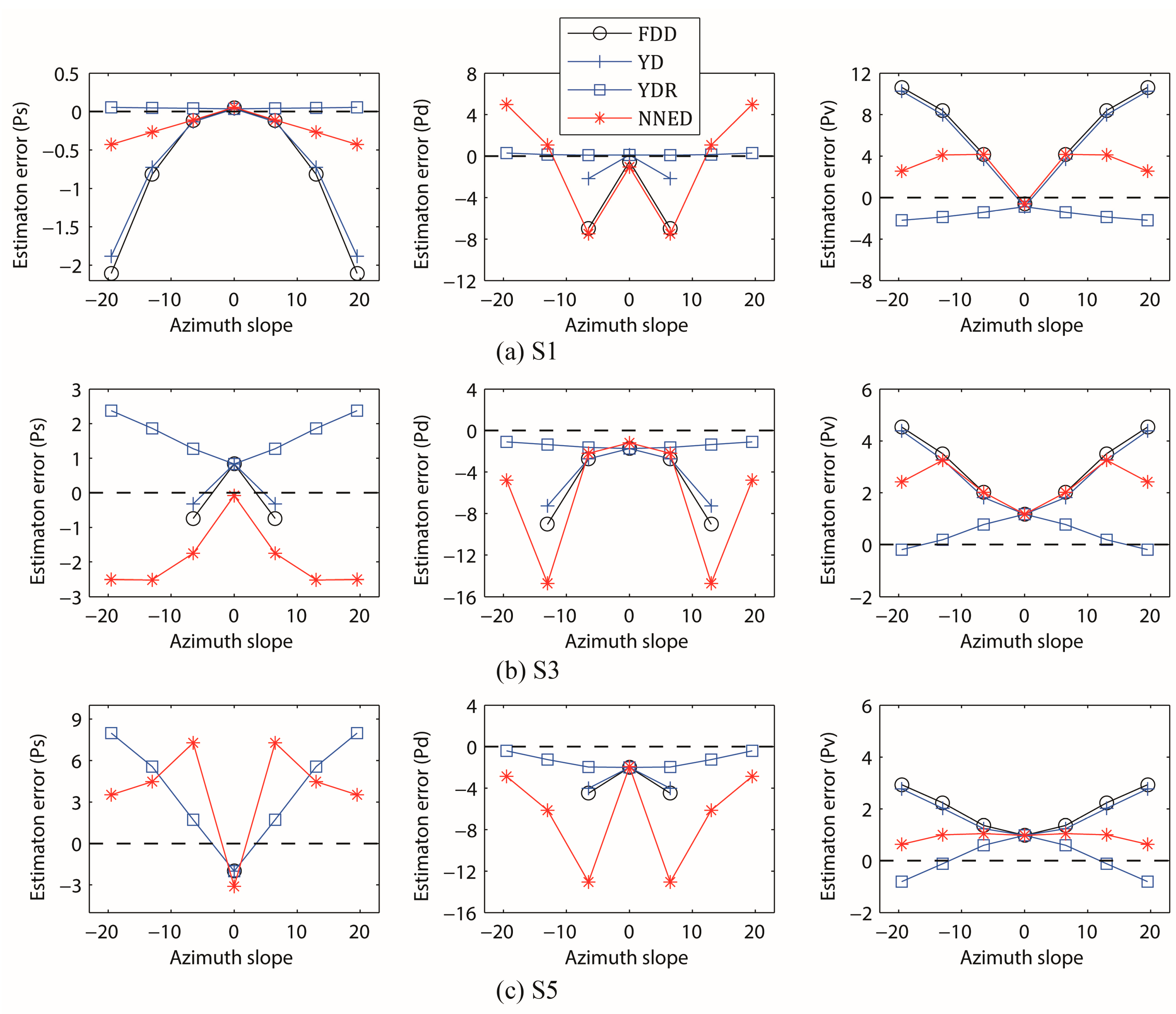
Figure 6 shows the estimation errors with respect to the azimuth slope of the ground plane, where the range slope angle is set to zero. In Table 3, the RMSE for the azimuth slope variation are also presented. In this case, the four decomposition approaches show different performances, but in general, the estimation errors are much dependent on the azimuth slope.
The FDD and YD methods show similar angular trends in terms of the estimation error, although the YD method provides slightly lower RMSE than the FDD method. The estimation error of the volume scattering component in this case increases proportionally to the azimuth slope angle. The overestimation problem according to azimuth slope becomes more marked in the presence of less vegetation: RMSE values are more than 7 dB for S1 and around 2 dB for S5. It should be noted that the FDD and YD methods nearly fail to estimate the surface and the double-bounce scattering components with the presence of a terrain azimuthal slope greater than around 10°. When the surface scattering is dominant among backscattered signals, the FDD and YD methods can provide non-negative surface scattering components, but still significantly underestimate the true surface scattering powers.
Figure 6. Estimation errors (in dB) of model-fitting-based decomposition methods with respect to the azimuth slope angle. The first, second and third row are errors for three different size categories: (a) S1, (b) S3, and (c) S5.
Remotesensing 07 04997 g006
Table 3. RMSE of each decomposition method for the azimuth slope variation. Shaded cells represent that an azimuth profile of the calculated scattering component contains negative power.
S1S2S3S4S5
FDDYDYDRNNEDFDDYDYDRNNEDFDDYDYDRNNEDFDDYDYDRNNEDFDDYDYDRNNED
P s 1.211.080.050.286.035.060.501.0333.3333.331.782.1231.3331.243.293.7634.9534.955.335.07
P d 24.2924.030.184.8624.1424.131.405.7826.1325.971.438.3737.1137.111.344.9536.2836.261.477.89
P v 7.587.241.753.433.523.360.582.793.283.120.622.462.802.650.571.612.131.980.660.92
The NNED method reduces the amount of overestimation in the volume scattering component, so as to mitigate negative power problems in the estimated surface and double-bounce scattering components. Nonetheless, the NNED method still overestimates the volume scattering powers up to 4 dB in the case of S1. The double-bounce scattering component is significantly underestimated with RMSE values more than 4 dB in all tree types. The surface scattering component is also overestimated particularly in the case of large trees, showing higher RMSE values than those in the volume scattering.
It is evident that the YDR method not only mitigates negative power problems, but also provides the best performance in the estimation of the volume scattering component with RMSE values less than 1 dB for all vegetation types, except S1. The double-bounce scattering is slightly underestimated, but the estimation error can also be significantly reduced with RMSE values less than 1.5 dB. On the other hand, the estimation error of the surface scattering component increases proportionally to the azimuth slope angle with the RMSE increasing to more than 7 dB in the case of large trees.

4. Conclusions

The effect of ground topography on the model-fitting-based polarimetric decomposition techniques was studied. The estimation accuracy of each scattering component in the decomposition results was evaluated based on the simulated target matrix by using the incoherent vegetation scattering model that accounts for the tilted scattering surface beneath the forest canopy. The performance of four frequently used decomposition methods was examined for different sizes of trees on the sloping ground.
The ground tilt in the azimuth direction causes the cross-polarization backscatter, resulting in overestimation of the volume scattering component and negative power problems in the surface and the double-bounce scattering components in the decomposition results. In fact, azimuth slope influences have been well understood, particularly in weakly-vegetated areas. As reported in the literature, e.g., [6,7,15], the orientation angle compensation can improve the estimation performance of the volume scattering powers and mitigate negative power problems. However, there exists a significant amount of azimuth-slope-induced errors, particularly in the estimation of signals scattered from the ground surface underneath the vegetation. This shows that the unitary rotational transformation applied to the total backscattered return cannot completely resolve estimation errors related to the topography of the underlying forest floor.
In addition, the ground tilt in the range direction also induces estimation errors in surface scattering powers, particularly in slopes facing away from the radar. Furthermore, there exists a significant amount of range-slope-induced errors in the estimation of double-bounce scattering powers. It is evident that the double-bounce scattering model in the decomposition techniques, which only takes into account the coherent specular scattering, cannot properly address the actual characteristics of the scattering interaction between the vegetation and the underlying sloping surface.
In order to improve the model-fitting performance in the polarimetric decomposition, several recent studies have focused on improving the estimation accuracy of the volume scattering power [16,17,18,19]. However, experimental results in this study demonstrate that, even when the volume scattering power is successfully estimated, the ground-related scattering components can be significantly misestimated due to the topographic slope. Consequently, further research is required to improve the model formulation of the surface and the double-bounce scattering components with additional parameters considering the local coordinate shift of the slanted ground plane, both in the forward and backward scattering components. This will be particularly important for P-band applications, because double-bounce returns from trunk-ground or canopy-ground interactions will be enhanced at the P-band frequency.

Acknowledgments

This work was partly supported by the faculty research fund of Sejong University and Space Core Technology Development Program through MEST (Ministry of Education Science and Technology) (NRF-2014M1A3A3A03034799).

Conflicts of Interest

The authors declare no conflict of interest.

References and Notes

  1. Cloude, S.R.; Pottier, E. A review of target decomposition theorems in radar polarimetry. IEEE Trans. Geosci. Remote Sens. 1996, 34, 498–518. [Google Scholar] [CrossRef]
  2. Cloude, S.R.; Pottier, E. An entropy based classification scheme for land applications of polarimetric SAR. IEEE Trans. Geosci. Remote Sens. 1997, 35, 68–78. [Google Scholar] [CrossRef]
  3. Park, S.-E.; Moon, W.M. Unsupervised classification of scattering mechanisms in polarimetric SAR data using fuzzy logic in entropy and alpha plane. IEEE Trans. Geosci. Remote Sens. 2007, 45, 2652–2664. [Google Scholar] [CrossRef]
  4. Freeman, A.; Durden, S.L. A three-component scattering model for polarimetric SAR data. IEEE Trans. Geosci. Remote Sens. 1998, 36, 963–973. [Google Scholar] [CrossRef]
  5. Yamaguchi, Y.; Moriyama, T.; Ishido, M.; Yamada, H. Four-component scattering model for polarimetric SAR image decomposition. IEEE Trans. Geosci. Remote Sens. 2005, 43, 1699–1706. [Google Scholar]
  6. Yamaguchi, Y.; Sato, A.; Boerner, W.M.; Sato, R.; Yamada, H. Four-component scattering power decomposition with rotation of coherency matrix. IEEE Trans. Geosci. Remote Sens. 2011, 49, 2251–2258. [Google Scholar]
  7. Van Zyl, J.J.; Arii, M.; Kim, Y. Model-based decomposition of polarimetric SAR covariance matrices constrained for nonnegative eigenvalues. IEEE Trans. Geosci. Remote Sens. 2011, 49, 3452–3459. [Google Scholar]
  8. Shan, Z.; Zhang, H.; Wang, C.; An, W.; Wu, T.; Chen, X. Four-component model-based decomposition of polarimetric SAR data for special ground objects. IEEE Geosci. Remote Sens. Lett. 2012, 9, 989–993. [Google Scholar] [CrossRef]
  9. Sato, A.; Yamaguchi, Y.; Singh, G.; Park, S.-E. Four-component scattering power decompo-sition with extended volume scattering model. IEEE Geosci. Remote Sens. Lett. 2012, 9, 166–170. [Google Scholar] [CrossRef]
  10. Chen, S.; Ohk, M.; Shimada, M.; Sato, M. Deorientation effect investigation for model-based decomposition over oriented built-up areas. IEEE Geosci. Remote Sens. Lett. 2013, 10, 273–277. [Google Scholar] [CrossRef]
  11. Van Zyl, J.J.; Chapman, B.D.; Dubois, P.; Shi, J. The effect of topography on SAR calibration. IEEE Trans. Geosci. Remote Sens. 1993, 31, 1036–1043. [Google Scholar] [CrossRef]
  12. Ulander, L.M.H. Radiometric slope correction of synthetic aperture radar images. IEEE Trans. Geosci. Remote Sens. 1996, 34, 1115–1122. [Google Scholar] [CrossRef]
  13. Park, S.-E.; Moon, W.M.; Pottier, E. Assessment of scattering mechanism of polarimetric SAR signal from mountainous forest areas. IEEE Trans. Geosci. Remote Sens. 2012, 50, 4711–4719. [Google Scholar] [CrossRef]
  14. Ulaby, F.T.; Moore, R.K.; Fung, A.K. Microwave Remote Sensing: Active and Passive, Vol. II; Addison-Wesley, Advanced Book Program: Reading, MA, USA, 1982; pp. 949–966. [Google Scholar]
  15. Lee, J.S.; Shuler, D.L.; Ainsworth, T.L.; Krogager, E.; Kasilingam, D.; Boerner, W.M. On the estimation of radar polarization orientation shifts induced by terrain slopes. IEEE Trans. Geosci. Remote Sens. 2002, 40, 30–41. [Google Scholar] [CrossRef]
  16. Arii, M.; Van Zyl, J.J.; Kim, Y. Adaptive model-based decomposition of polarimetric SAR covariance matrices. IEEE Trans. Geosci. Remote Sens. 2011, 49, 1104–1113. [Google Scholar] [CrossRef]
  17. Antropov, O.; Rauste, Y.; Hame, T. Volume scattering modeling in PolSAR decompositions: Study of ALOS PALSAR data over boreal forest. IEEE Trans. Geosci. Remote Sens. 2011, 49, 3838–3848. [Google Scholar] [CrossRef]
  18. Cui, Y.; Yamaguchi, Y.; Yang, J.; Park, S.-E.; Kobayashi, H.; Singh, G. Three-component power decomposition for polarimetric SAR data based on adaptive volume scattering modeling. Remote Sens. 2012, 4, 1559–1572. [Google Scholar] [CrossRef]
  19. Chen, S.-W.; Wang, X.-S.; Li, Y.-Z.; Sato, M. Adaptive model-based polarimetric decomposition using PolInSAR coherence. IEEE Trans. Geosci. Remote Sens. 2014, 52, 1705–1718. [Google Scholar] [CrossRef]

