Article

Erosion Relevant Topographical Parameters Derived from Different DEMs—A Comparative Study from the Indian Lesser Himalayas

by
Pawanjeet S. Datta
* and
Helmer Schack-Kirchner
Institute of Soil Science and Forest Nutrition, Faculty of Forest and Environmental Science, Albert-Ludwigs University Freiburg, 79085 Freiburg i.Br., Germany
*
Author to whom correspondence should be addressed.
Remote Sens. 2010, 2(8), 1941-1961; https://doi.org/10.3390/rs2081941
Submission received: 30 June 2010 / Revised: 2 August 2010 / Accepted: 2 August 2010 / Published: 13 August 2010

Abstract

:
Topography is a crucial surface characteristic in soil erosion modeling. Soil erosion studies use a digital elevation model (DEM) to derive the topographical characteristics of a study area. Majority of the times, a DEM is incorporated into erosion models as a given parameter and it is not tested as extensively as are the parameters related to soil, land-use and climate. This study compares erosion relevant topographical parameters—elevation, slope, aspect, LS factor—derived from 3 DEMs at original and 20 m interpolated resolution with field measurements for a 13 km2 watershed located in the Indian Lesser Himalaya. The DEMs are: a TOPO DEM generated from digitized contour lines on a 1:50,000 topographical map; a Shuttle Radar Topography Mission (SRTM) DEM at 90-m resolution; and an Advanced Spaceborne Thermal Emission and Reflection Radiometer (ASTER) DEM at 15-m resolution. Significant differences across the DEMs were observed for all the parameters. The highest resolution ASTER DEM was found to be the poorest of all the tested DEMs as the topographical parameters derived from it differed significantly from those derived from other DEMs and field measurements. TOPO DEM, which is, theoretically more detailed, produced similar results to the coarser SRTM DEM, but failed to produce an improved representation of the watershed topography. Comparison with field measurements and mixed regression modeling proved SRTM DEM to be the most reliable among the tested DEMs for the studied watershed.

1. Introduction

One of the most important factors affecting soil erosion by water is topography [1]. Digital elevation models (DEMs) have been commonly used in a geographic information system (GIS) for representing topography and for extracting topographical and hydrological features for various applications, including soil erosion studies [2]. DEMs can be generated by several techniques which include ground surveys, topographical maps, stereo photogrammetry, laser scanning and InSAR [3]. Shuttle Radar Topography Mission (SRTM) collected data in 2000 using InSAR technique which has been processed to generate DEMs with 1 arcsecond (approximately 30 m) and 3 arcsecond (approximately 90 m) spatial resolutions [4]. Advanced Spaceborne Thermal Emission and Reflection Radiometer (ASTER), an advanced multispectral imager launched in December 1999, has been used to generate DEMs with 15-m spatial resolution [5]. An alternative, and the most widely used method of obtaining a DEM, is to interpolate it from vectorized contour lines digitized from regional topographical maps.
Soil erosion is a serious problem in the fragile Lesser Himalayas. Steep slopes, sparse vegetation, high rainfall intensities and unstable geology, coupled with one of the densest human populations, have combined to produce some of the highest reported soil erosion rates in the entire Himalayan region [6,7,8]. Various efforts have been made to quantify soil losses and to understand the effects of soil erosion in the Lesser Himalayan region using soil erosion modeling tools. Both empirical soil erosion models and, to a lesser extent, physically based soil erosion models have been used in these studies. Shrestha [9] observed soil losses ranging from <1 Mg/ha/yr for Dense Forest to 56 Mg/ha/yr for a Himalayan watershed in Nepal using MMF model (Morgan, Morgan and Finney model, [10]). Kumar and Sharma [11] used the MMF model to assess soil erosion from a western Himalayan watershed and found soil losses ranging from 3.5 Mg/ha/yr for dense forest to 92.6 Mg/ha/yr for steep open scrub. Jain et al. [12] applied MMF and USLE (Universal Soil Loss Equation, [13]) models to a watershed in western Himalaya and estimated soil losses ranging from 1.2 Mg/ha/yr for dense forest to 74.9 Mg/ha/yr for fallow using MMF. USLE, in the same study [12], estimated soil losses from 2.0 Mg/ha/yr to 198.7 Mg/ha/yr for dense forest and fallow respectively. Hessel et al. [14] used the physically based LISEM (Limburg Soil Erosion Model, [15,16]) in Arnigad watershed in the Lesser Himalayas and obtained soil losses of 4 to 27 Mg/ha for individual rainfall events.
All the above studies, except [14] which used an ASTER DEM, derived the slope and other topographical input parameters by digitizing contour lines from topographical maps. The large variations in the range of soil loss estimates in the different studies mentioned above may be due to a multitude of factors. One factor which could have significantly affected the erosion modeling outputs is the terrain description, in the form of DEM, used to describe the topography of the study sites.
DEM source and resolution have been shown, by many studies, to affect the accuracy of the extracted topographical parameters. De Vente et al. [17] observed SRTM DEM to provide more accurate estimates of slope gradient and upslope drainage area than ASTER DEM. Jenson [18] found slopes generated from 30 arcsecond (approximately 1km resolution) DEM to be smaller than slopes generated from a 3 arcsecond (approximately 90-m resolution) DEM. Wolock and McCabe [19] found differences in slope, specific catchment area and wetness index computed from DEMs interpolated to 100-m and 1000-m resolutions. Zhang et al. [2] found that DEMs with different resolutions and sources generated varied watershed shapes and structures leading to different extracted hillslopes, channel lengths and gradients, producing substantially different erosion predictions by Water Erosion Prediction Project (WEPP). These studies, beside others, lead to an evident observation that the choice of DEM plays a very important role in minimizing the errors in topographical attributes generated from a DEM. Often, however, DEMs have been incorporated in soil erosion studies as a given parameter without testing their suitability for terrain modeling at the desired scale of the study in contrast to other parameters related to soil, land-use and climate.
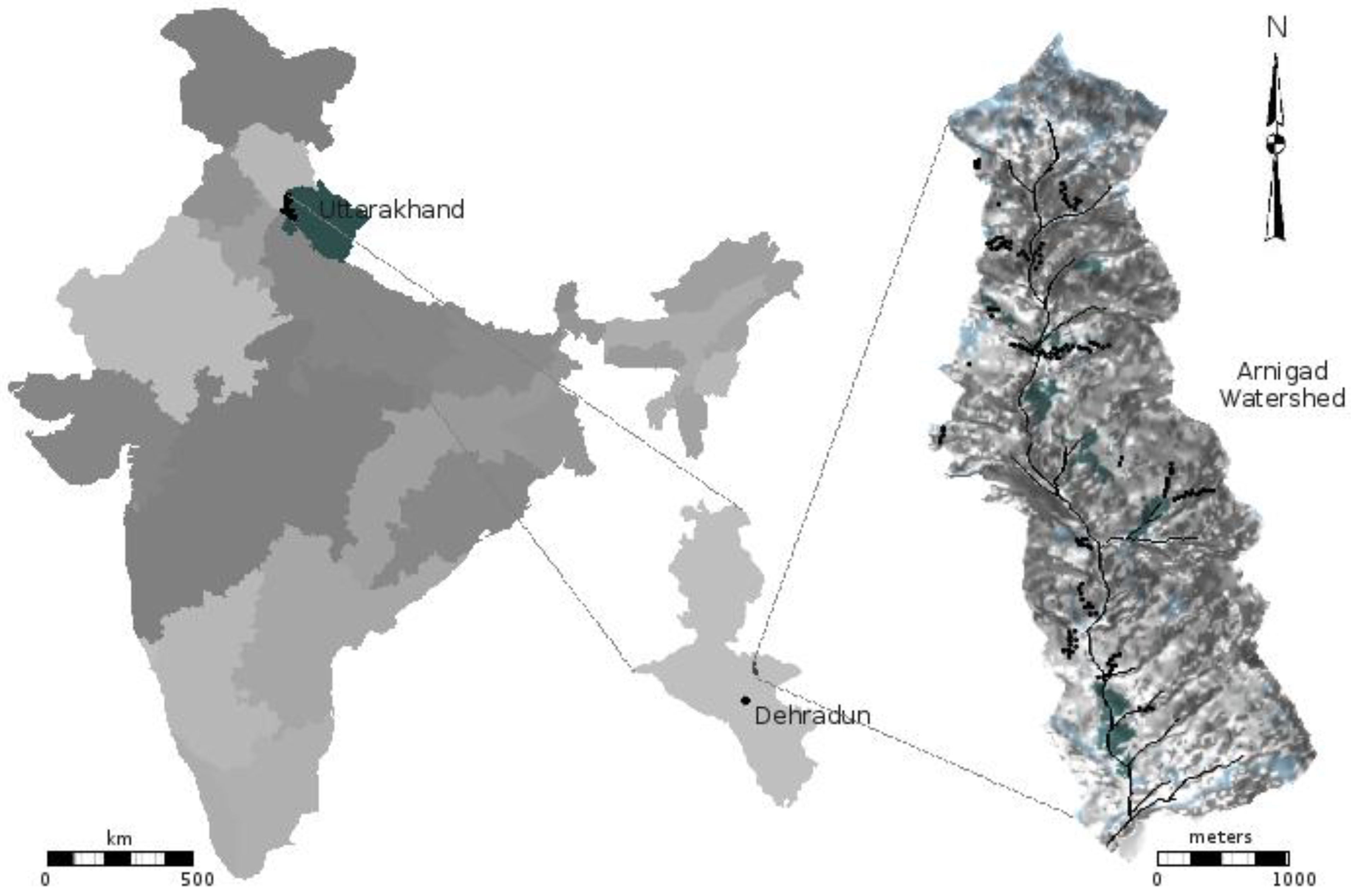
This study compares, for a small watershed in the Indian Lesser Himalayas (Figure 1), erosion relevant topographical parameters namely elevation, slope, aspect and LS factor computed using DEMs from three different sources at their original and interpolated 20-m spatial resolutions. The DEMs and the derived topographical parameters are also compared with field observations. The DEMs used in this study are two SRTM DEMs at 90-m original and 20-m interpolated resolutions, two ASTER DEMs at 15-m original and 20-m interpolated resolutions and a topographical DEM generated from contour lines on a 1:50,000 topographical map. The aims of this study are to compare the DEMs with field observations and to assess the effect of different DEMs on erosion relevant topographical parameters.
Figure 1. Location of the study watershed in Uttarakhand, India and a view of the watershed showing the field sampling locations.
Remotesensing 02 01941 g001

2. Materials and Methodology

2.1. Study Area

The study area, Arnigad watershed (30°22′N–30°27′N and 78°04′E–78°08′E) is a typical Lesser Himalayan watershed located to the northeast of Dehradun in the Indian state of Uttarakhand (Figure 1). The 13 km2 watershed is characterized by large elevation changes over short distances resulting in a steep mountainous terrain and an altitudinal range extending from 900 m to 2,200 m above sea level. The catchment is underlain by Pre-Cambrian to early Paleozoic sedimentary rocks mainly limestones and dolomites but also slates and shales along with recent and subrecent deposits [20]. The soils are shallow in depth with increasing presence of gravel, stones and boulders in the lower horizons [21].
Climate in the watershed is typically monsoonic characterized by single monsoon season lasting from June to September. The average annual rainfall is about 2000 mm of which about 75 percent occurs during the monsoon months [22].
The higher elevations of the catchment consist of relatively dense Quercus leucotrichophora (ban oak) forests, whereas, in the middle and lower parts, the forests are degraded and comprise bushy vegetation including Lantana camera (lantana), Murraya koenigii (curry-leaf tree), Adhatoda vasica (adulsa) and Berberis sps. A scattering of habitation structures belonging to the town Mussoorie are located in the northwestern part of the catchment. There are also a number of small villages where agriculture is concentrated on terraces covering about 4 percent of the watershed area [14].
The Main Boundary Fault separating the Siwalik from the pre-Siwalik Tertiaries passes adjacent to the study watershed showing the region to be tectonically active. Soil erosion is a common problem in the area due to a combination of natural factors (steep slopes, unstable geology, high rainfall intensity, etc.), harmful practices, and macro-policy and demand related factors.

2.2. Remote Sensing and GIS Data Processing

2.2.1. DEM Source and Information

ASTER sensor onboard the National Aeronautics and Space Administration (NASA) Terra satellite provides images with visible and near infrared (VNIR) bands in 15-m spatial resolution, and short-wave and thermal infrared bands in 30-m and 90-m resolution, respectively [5]. Stereocorrelation, which is a computational and statistical procedure, has become a standard method for generating DEMs from stereopairs of digital satellite images [23]. This procedure was used to prepare a DEM of the study area with a spatial resolution of 15-m from ASTER data obtained between October, 2000 and March, 2002. The ground control points for the geometrical correction of the DEM were obtained using a GPS. This finished DEM prepared at the University of Wales at Swansea was provided by Alterra, Wageningen University and this DEM has been used to generate topographical inputs in a previous study [14] in the same watershed.
SRTM is a project spearheaded by the National Geospatial-Intelligence Agency (NGA) and NASA. This project provided elevation data on a near-global scale to generate the most complete digital topographic database of Earth. A DEM based on SRTM data for the study area was obtained at a spatial resolution of 30 arcsecond (approximately 90-m) from Earth Science Data Interface (ESDI) at Global Land Cover Facility (GLCF) of the University of Maryland. The DEM with UTM projection was obtained as ‘Filled Finished-A’ product and the voids in the data set had already been removed by nearest neighbor interpolation [24].
A Survey of India (SOI) topographical map of the study area at 1:50,000 scale was used to extract a third DEM by digitizing the contour lines at 20 m intervals. In this paper SRTM based maps and data will be referred to as SRTM, the ASTER based maps and data will be referred to as ASTER and the data based on the topographic map will be referred to as TOPO.

2.2.2. DEM Data Processing

GRASS GIS 6.3 was used for processing the DEMs and for generating mapsets of the topographical attributes. Since both SRTM and ASTER data were obtained from their respective sources as prepared DEMs, the only preprocessing done on these was rasterization into the GIS. To obtain the TOPO DEM contour lines at 20 m intervals were extracted from the SOI toposheet. The DEM was created using GRASS GIS 6.3 by spatial approximation based on the elevation attributes of the vector map containing the contour lines. This spatial approximation was performed using regularized spline with tension [25,26] and the DEM was created at a 20-m spatial resolution.
Interpolation using regularized spline and tension was also used to resample original SRTM and ASTER DEMs to obtain their corresponding 20-m resolution DEMs. ASTER DEM was smoothed from 15-m to 20-m resolution and SRTM DEM was discretized from 90-m to 20-m. The scaling of all the DEMs to 20-m resolution was done to facilitate the comparison of the results. Wolock and McCabe [19] observed that terrain-discretization effect of DEM resolution are more pronounced on relatively flat terrain while the terrain-smoothing effects are more apparent on relatively steep terrain. Due to the relatively steep nature of the study watershed the variable extents of the interpolation spans were used for SRTM and TOPO DEMs so as to balance the discretization and smoothing effects.
For both spatial approximation of TOPO DEM and re-interpolation of SRTM and ASTER DEMs, the default tension and smoothing parameters of the GRASS GIS 6.3 module were found to be the most suitable. The five DEMs hence obtained—namely TOPO 20m, SRTM 90m, SRTM 20m, ASTER 15m and ASTER 20m—were subsequently used in this study. Sinks or depressions in all the DEMs were filtered out by the drainage analysis technique, wherein the cells contained in depressions are raised to the lowest elevation value on the rim of the depression [27]. The procedures used for the above processing steps have been described in detail in [28].

2.2.3. DEM Horizontal Accuracy

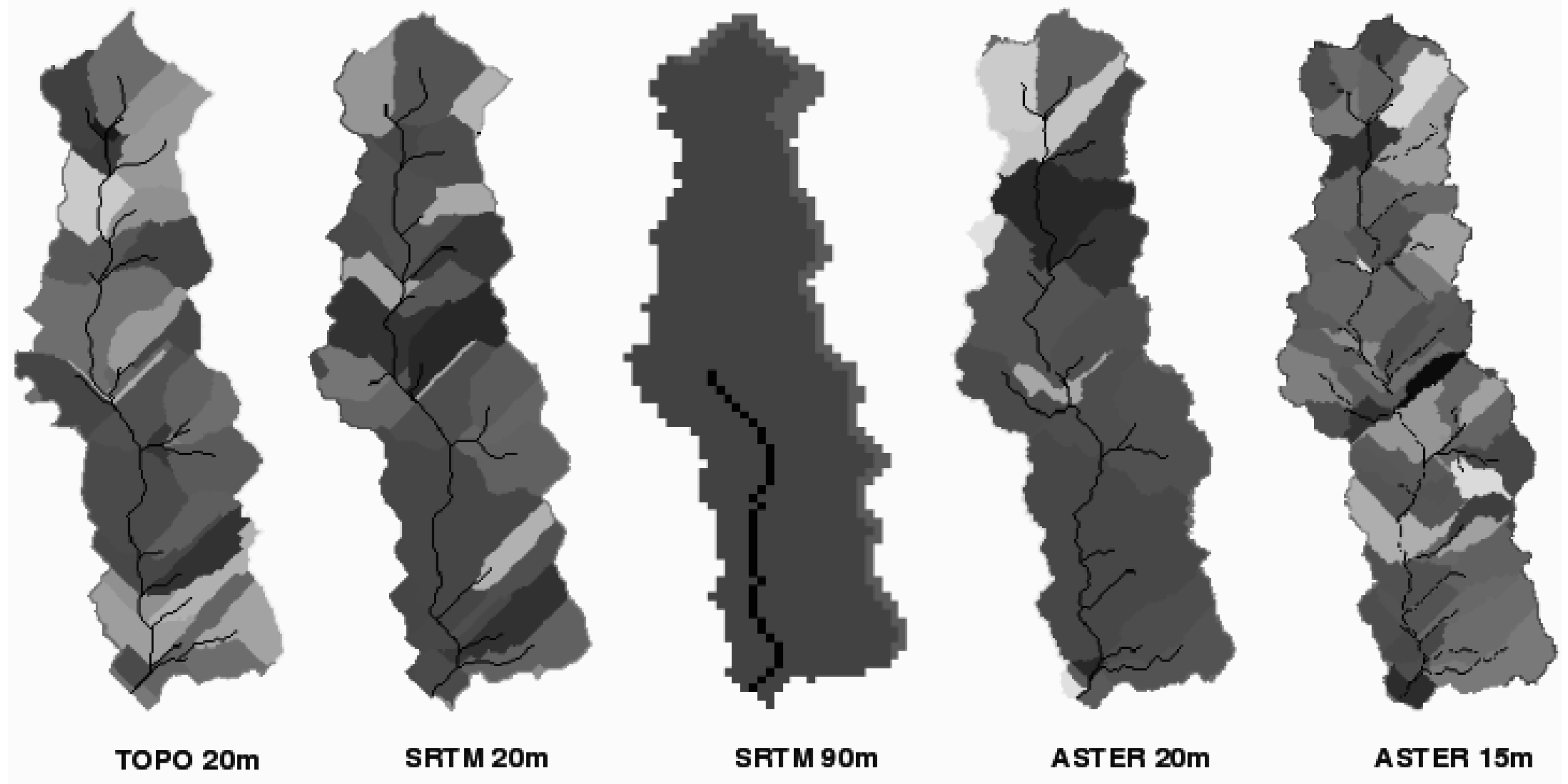
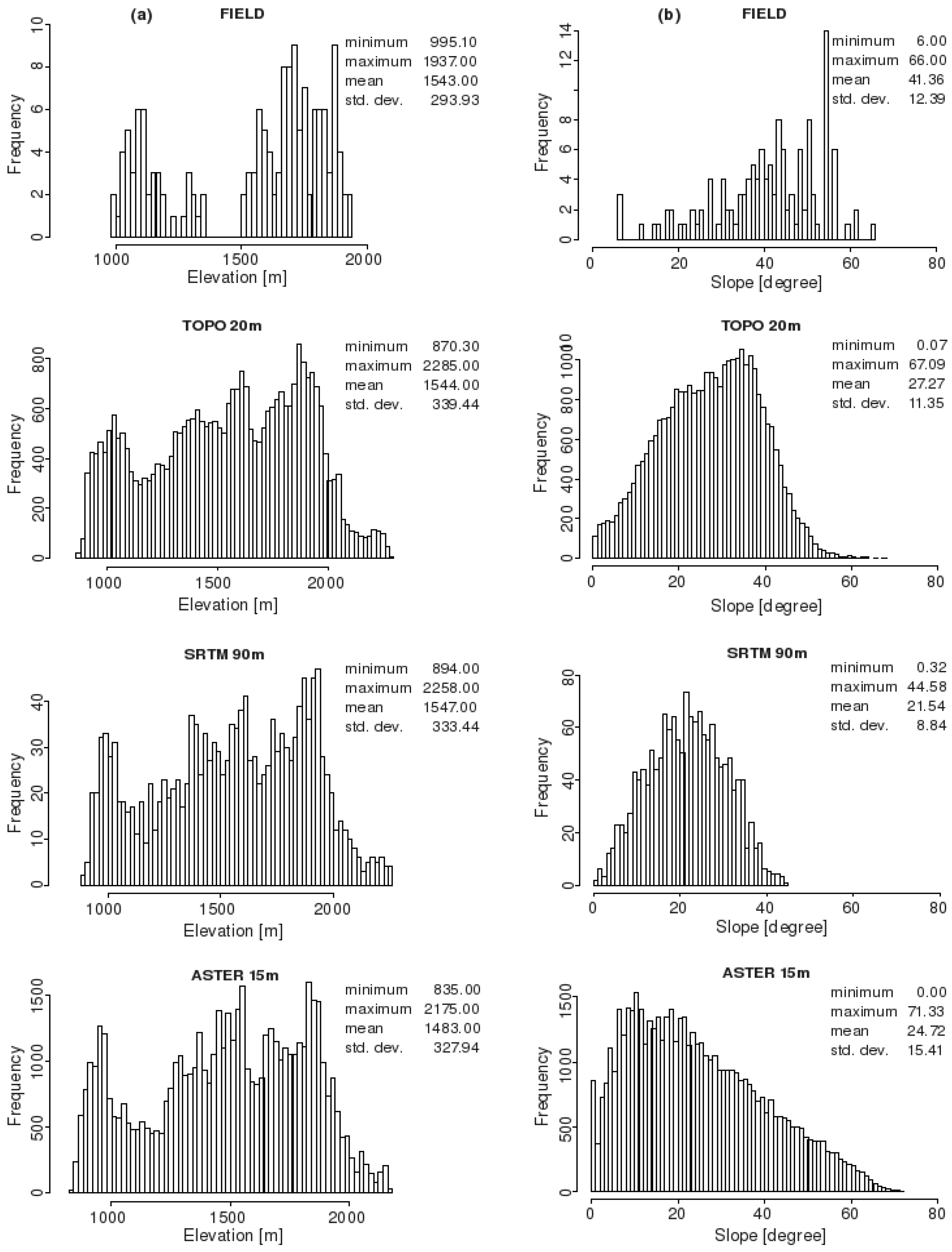
The horizontal consistency of the DEMs is a prerequisite for their further comparative analysis. In studies where DEMs from different sources are compared, the horizontal shift could have important implications if the DEMs show any misalignment as was observed by [29] between ASTER and SRTM DEMs. To check the horizontal accuracy, the DEMs were superimposed on one another and observed for any potential misalignments. Comparisons of drainage networks derived from the DEMs as well as DEM elevation histograms show a similar pattern of streams (Figure 2) and appearance of peaks for frequency histograms (Figure 3a) respectively, thereby suggesting no large horizontal errors in the DEMs.
Figure 2. Watershed basins and stream channels represented by the DEMs at original and interpolated resolutions.
Remotesensing 02 01941 g002
Figure 3. Frequency histograms and univariate statistics showing (a) field measured elevations and DEM derived elevations at original resolutions, and (b) field measured slopes and DEM derived slopes at original resolutions.
Remotesensing 02 01941 g003
The horizontal accuracy was further analyzed by comparing several elevation profiles in the north–south and east–west directions for all the DEMs. The pattern of peaks and valleys for each of the DEMs was observed for any horizontal shift in comparison to the rest of the DEMs. The TOPO DEM was found to be systematically shifted by approximately 60 m in the east direction which corresponds to 3 pixels. The DEM was corrected by shifting it 3 pixels towards the west which solved the misalignment of the peaks and valleys in all the observed east–west profiles. Some inconsistencies were observed for a few peaks in the ASTER DEMs but these were considered to be a limitation of the overall quality of the DEMs rather than being a horizontal shift.

2.3. Dataset Generation

2.3.1. Field Sampling

Extensive field data was collected in the Arnigad watershed during 4 months from October 2007 to February 2008. Field sampling was done at 152 locations spread throughout the watershed along a number of transects. The number of sampling locations per transect depended on the spatial extents of the hillslopes and in some cases on the accessibility of the terrain. The topographical parameters discussed in this study, namely elevation, slope and aspect, were measured at all the sampled locations shown in Figure 1. Besides topographical information, data was also collected for different soil parameters and erosion traces which will be used for the next stage of the project.

2.3.2. Elevation

The DEMs were visually assessed to observe their conformance to the field knowledge of the terrain shape and their consistency in representing the prominent geomorphic features like drainage networks and ridges. The elevation frequency histograms were compared to look for major inconsistencies in representability among the DEMs.
Elevations were measured in the field at 152 locations using a barometric altimeter with a vertical resolution of 50-cm. The barometer was calibrated for elevation at a fixed landmark and the daily altitudinal deviations were distributed linearly among all the measured points for that day. The DEMs were finally checked against these measured elevations and the elevation differences were analyzed.

2.3.3. Slope, Aspect and Channels

The primary terrain attributes of slope and aspect were calculated for all the five DEMs using Horn’s formula [30]. GRASS GIS 6.3 computes these parameters based on approximation of the terrain surface by a second order polynomial. The partial derivatives needed for the estimation of slope and aspect were then computed as weighted averages of elevation differences in the 3 × 3 neighborhood around the given cell [28]. The output slope map represents the degrees of inclination from the horizontal. The output aspect map indicates the direction of slope gradients and the aspect categories represent the number of degrees of east increasing in the counterclockwise direction.
Field slopes were measured at the 152 locations using a handheld Suunto clinometer to the nearest degree, and the aspect was measured using a Suunto field compass. Tile scale, corresponding to averaged values for approximately 30 m × 30 m sized plots was used, for these field measurements. The tile scale, which provides a representative slope and aspect measurement for larger sized plots on the hillslopes, was selected for the comparative analysis over a localized point scale measurement because of its spatial resolution which is comparable with the DEM pixel sizes.
As with elevation, the DEM derived slopes were compared among each other and then statistically analyzed for differences from the field measured slopes.

2.3.4. LS Factor

The representation of the topographic erosion susceptibility by the different DEMs and the field measurements was shown by calculating the LS factor, which is the combined slope length and slope steepness index used in RUSLE (Revised Universal Soil Loss Equation) [31]. LS factor represents the ratio of soil loss on a given slope length and steepness to soil loss from a slope which is 22 m long and 5 degree steep [31]. The RUSLE LS factor is a modification in the factor used in USLE and can incorporate complex slopes so as to provide a better estimate of the topographic effect on erosion [32].
The topographical parameters obtained from each of the DEMs and the field measurements were used to generate the LS factors at the 152 field measured points. The RUSLE approach as presented by [31] was used to calculate the LS factor using the DEMs and the field measured data. The slope length factor (L) was calculated by:
L = (λ/22.13)m
where 22.13 is the length of a RUSLE unit plot, (m) is the slope-length exponent and (λ) is the slope length. The slope lengths were calculated for the DEMs from upslope flow-lengths which represent the distances from each cell to an upland flat point. It was complicated to measure the slope lengths in the field because of the extreme slope steepness and inaccessibility of the upslope areas in many cases. Therefore, the reference slope lengths were roughly estimated using topographical map and field knowledge of the watershed in combination with the three dimensional Google earth tool which was used to estimate the direction of the flow upslope of the field point.
The slope-length exponent (m) can be explained by:
m = β/(1 + β)
where (β) is the ratio of rill to interrill erosion for conditions when soil is moderately susceptible to both and can be computed based on [33] from:
Β = (sin α/0.0896)/[3.0(sin α)0.8 + 0.56]
where (α) is the slope angle in degrees. For the slope steepness factor (S), the equation proposed by [34], for slopes greater than 9 percent, was used because the average watershed slope was higher than 9 percent. S was calculated as:
S = (16.8 sin α − 0.50)
The topographical LS factor calculated from the different DEMs was compared with that calculated using field values. The effect of slope length and slope steepness on the LS-factor was also compared.

3. Results

3.1. Elevation

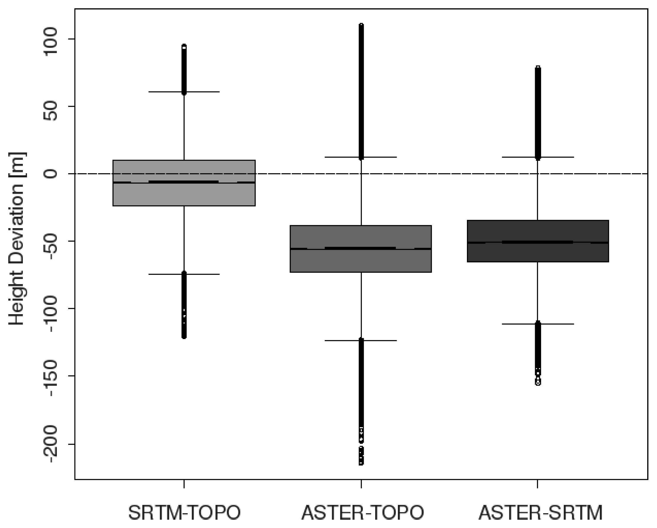
The three 20-m resolution DEMs were compared for absolute elevation differences. The results showed no significant differences between TOPO and SRTM DEMs whereas the ASTER elevations were found to be significantly lower than both TOPO and SRTM DEMs (Figure 4). The mean elevations in the ASTER DEM are lower than the TOPO and the SRTM DEMs by 53.71 m and 47.58 m respectively, while the SRTM DEM is lower than the TOPO DEM by a mean elevation of 6.47 m. At the same time, although elevation differences were observed between the original and interpolated SRTM and ASTER DEMs, these were not found to be significant.
Figure 4. Elevation differences at 20-m spatial resolution between SRTM, ASTER and TOPO DEMs.
Remotesensing 02 01941 g004
The RMSE between 152 field and DEM tiles was found to be higher than 50 m for all the DEMs with the SRTM 20m and SRTM 90m showing the lowest values of 50.60 m and 52.72 m respectively (Table 1). The RMSE for TOPO 20m was 53.47 m and, for the ASTER DEMs, it was the highest. Elevation deviations in the DEMs compared to the field measured elevations show all the DEMs, except TOPO 20m, to have negative mean errors suggesting an under-reporting of elevations by both the DEMs obtained by remote sensing (Table 2). The maximum under-reporting of mean elevations was observed in ASTER 15m and ASTER 20m while a slight over-reporting was observed in TOPO 20m. The elevation standard deviation on the other hand was observed to be the highest for TOPO 20m and lowest for the two ASTER DEMs.
Table 1. Correlation coefficient and root mean square error (RMSE) between DEM and field elevation, slope and LS factor values.
RMSETOPO DEMSRTM DEMASTER DEM
Resolution20-m20-m90-m20-m15-m
Elevation [m]53.4750.6052.7269.7670.94
Slope [°]19.6018.1521.3920.8921.31
LS factor47.7547.6541.6735.8833.10
Table 2. Univariate statistics showing DEM errors by subtracting field measured elevations from the DEM elevation values.
MinimumMaximumMeanStandard deviation
TOPO 20m−155.00105.204.4053.46
SRTM 20m−155.5076.70−13.2149.00
SRTM 90m−164.3096.33−12.5651.37
ASTER 20m−161.7010.15−57.2039.83
ASTER 15m−156.807.41−58.6640.02

3.2. Slope, Aspect and Channels

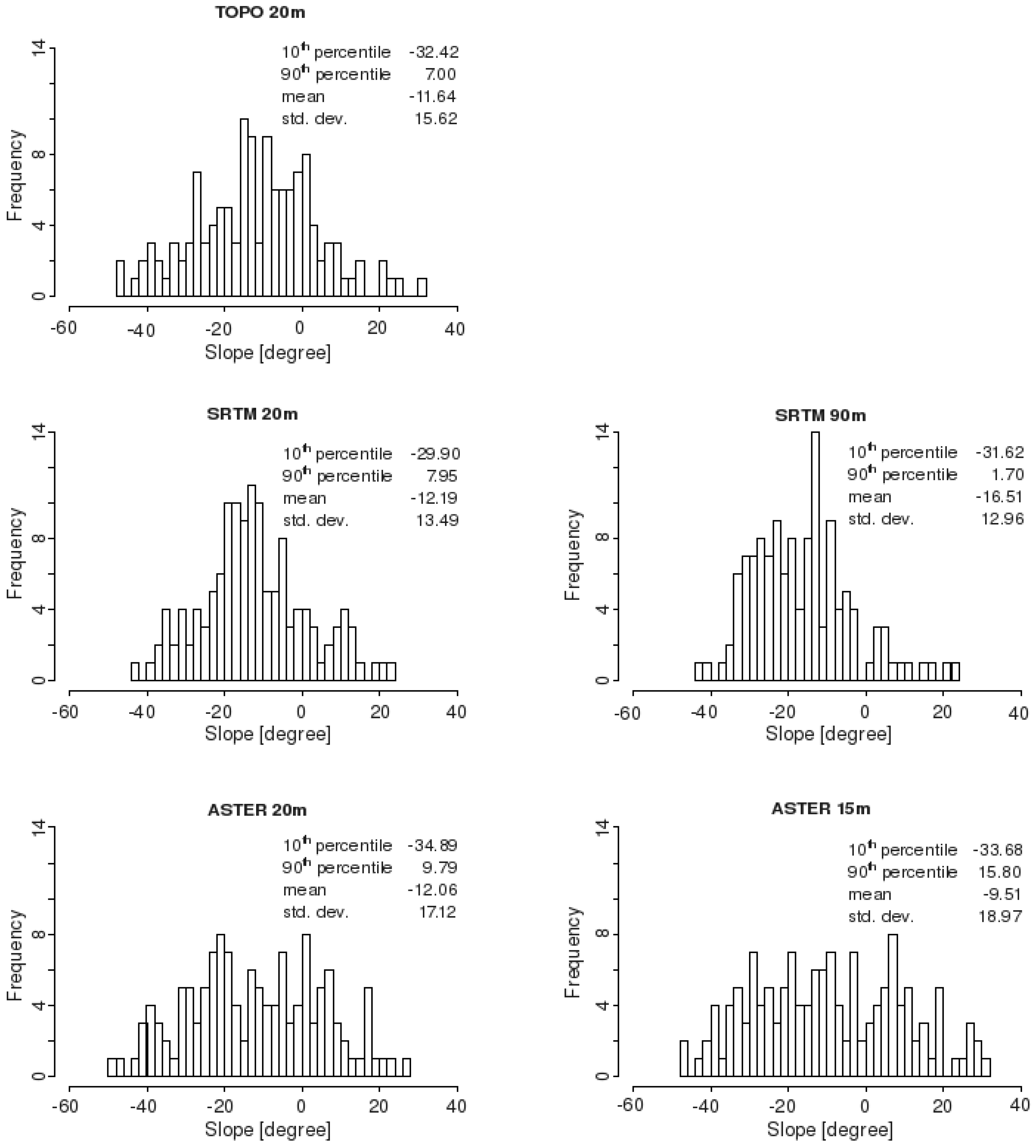
The histograms and descriptive statistics comparing the slopes derived from the three original DEMs and the measured slopes at 152 field areas are presented in Figure 3b. The mean slope is highest in case of TOPO 20m and lowest in SRTM 90m. The standard deviation from the mean and the slope range is higher for both the ASTER DEMs as compared to the other DEMs. The two ASTER DEMs are also positively skewed while both the SRTM and the TOPO DEMs are negatively skewed (Figure 3b).
The errors calculated by subtracting the field measured slopes from the DEM derived slopes have been presented in Figure 5 while the RSME of DEM slope compared to field slope is presented in Table 1. All the DEMs reported mean negative differences implying that the DEMs generated slopes were gentler compared to those measured in the field. The SRTM 90m had the lowest mean slope which was 16.19 degrees lower than the field measured slopes, while the other DEMs did not vary considerably from each other in their deviation from the actual field slopes. The error analysis further showed that the 10th percentile for the ASTER DEMs was slightly higher compared to the SRTM DEMs and the TOPO 20m DEM, while their 90th percentile and standard deviation values were considerably higher than all the other DEMs.
The inconsistencies between the aspect values derived from 20-m resolution DEMs and the field measured aspect values for 152 field measurements can be ascertained from the rose diagrams in Figure 6. All the DEMs showed directional bias missing the northerly directed slopes, which was in contrast to the field measured aspect values that were delineated in all directions. The highest missing slopes were observed in the TOPO 20m while the ASTER DEMs appear to have the widest range of aspect values.
The total watershed area was the highest for the SRTM DEMs which also produced the lowest number of hillslopes and channels while the ASTER DEMs had the smallest watershed areas but the highest number of hillslopes and channels (Table 3; Figure 2). For the total watershed area, the differences between the original and interpolated resolution were not very high for both SRTM and ASTER DEMs but for the number of hillslopes and channels the resulting differences were quite significant. The hillslope profile and the channel segments were extracted keeping the threshold limit of cells flowing into a stream constant for all the 20-m resolution DEMs.
Figure 5. Slope error frequency, mean error, standard deviation and error percentile for the five DEMs (errors calculated by subtracting field measured slopes from the DEM derived slopes).
Remotesensing 02 01941 g005
Figure 6. Rose diagrams showing the distribution of aspects in the field and as derived from 20-m resolution DEMs.
Remotesensing 02 01941 g006
Table 3. Total watershed area, number of hillslopes and flow channels as represented by different DEMs.
DEMArea (ha)No. of hillslopesNo. of channels
TOPO 20m1249.62137
SRTM 20m1276.42126
SRTM 90m1275.131
ASTER 20m1226.32329
ASTER 15m1227.72853

3.3. RUSLE LS Factors

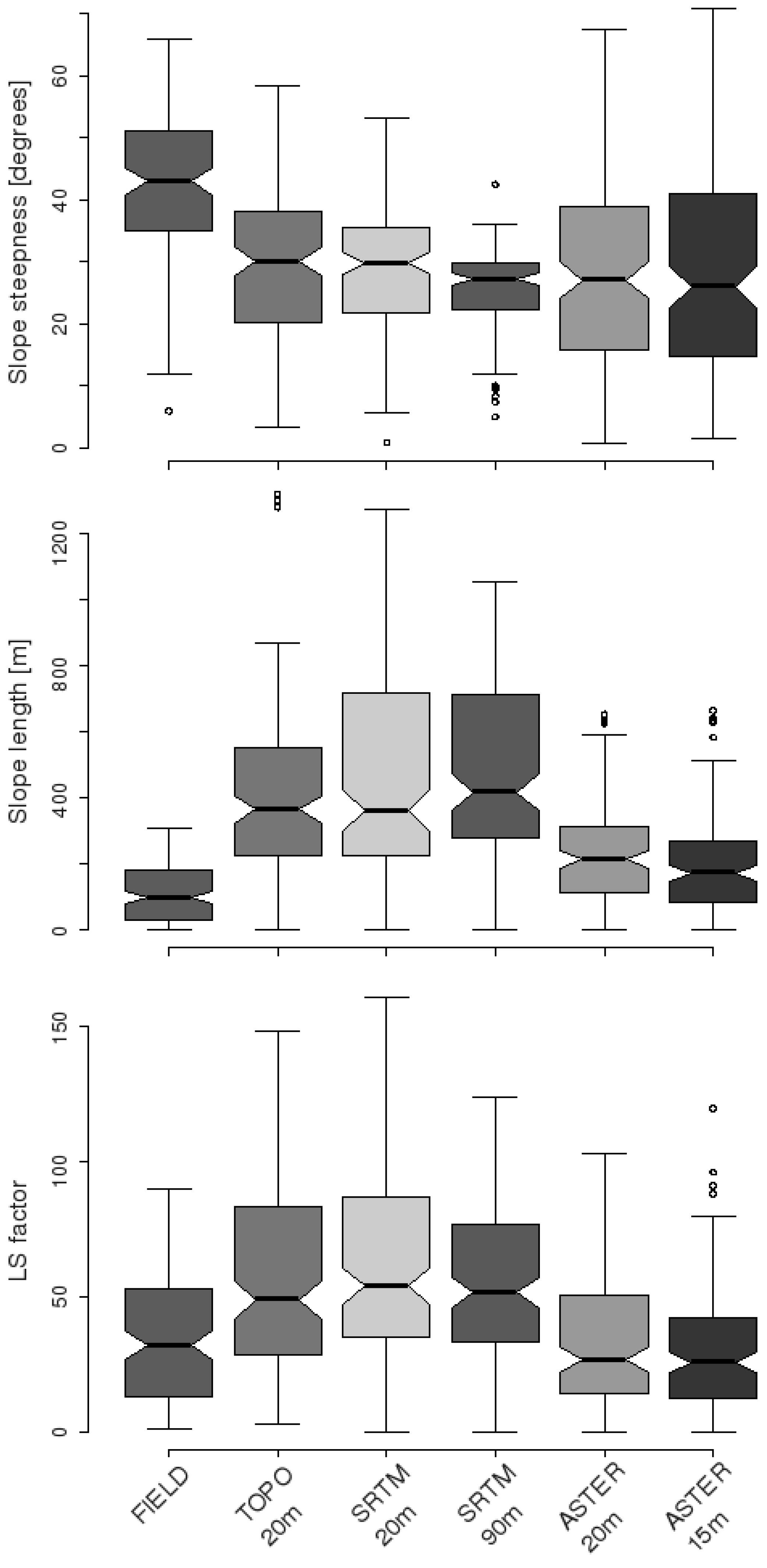
The topographical slope steepness, slope length and LS-factor for RUSLE calculated for 152 field measured and DEM generated points have been presented as boxplots in Figure 7. The results suggest a higher sensitivity of LS factor to slope length factor as compared to slope steepness factor. The LS factor values showed ASTER DEMS to have the lowest mean and median values, closer to LS factor obtained using the field measurements (Table 4; Figure 8) while TOPO and SRTM produced relatively higher LS factor values. RMSE of DEM derived LS factors compared to field measurements (Table 1) also suggest the ASTER DEMs to have the lowest values.
Figure 7. Boxplots comparing the field measured and DEM derived slope steepnesses, slope lengths and RUSLE LS factors at 152 locations.
Remotesensing 02 01941 g007
Table 4. Univariate statistics for RUSLE LS factor at 152 locations derived from field data and from the 5 DEMs.
MinimumMaximumMeanMedianStandard deviation
FIELD0.9589.5634.6231.9223.52
TOPO 20m2.75148.2057.2648.7136.42
SRTM 20m0160.8061.3253.8036.22
SRTM 90m0123.4054.0951.5229.27
ASTER 20m0102.7034.3926.5425.28
ASTER 15m0119.6030.2725.6023.18
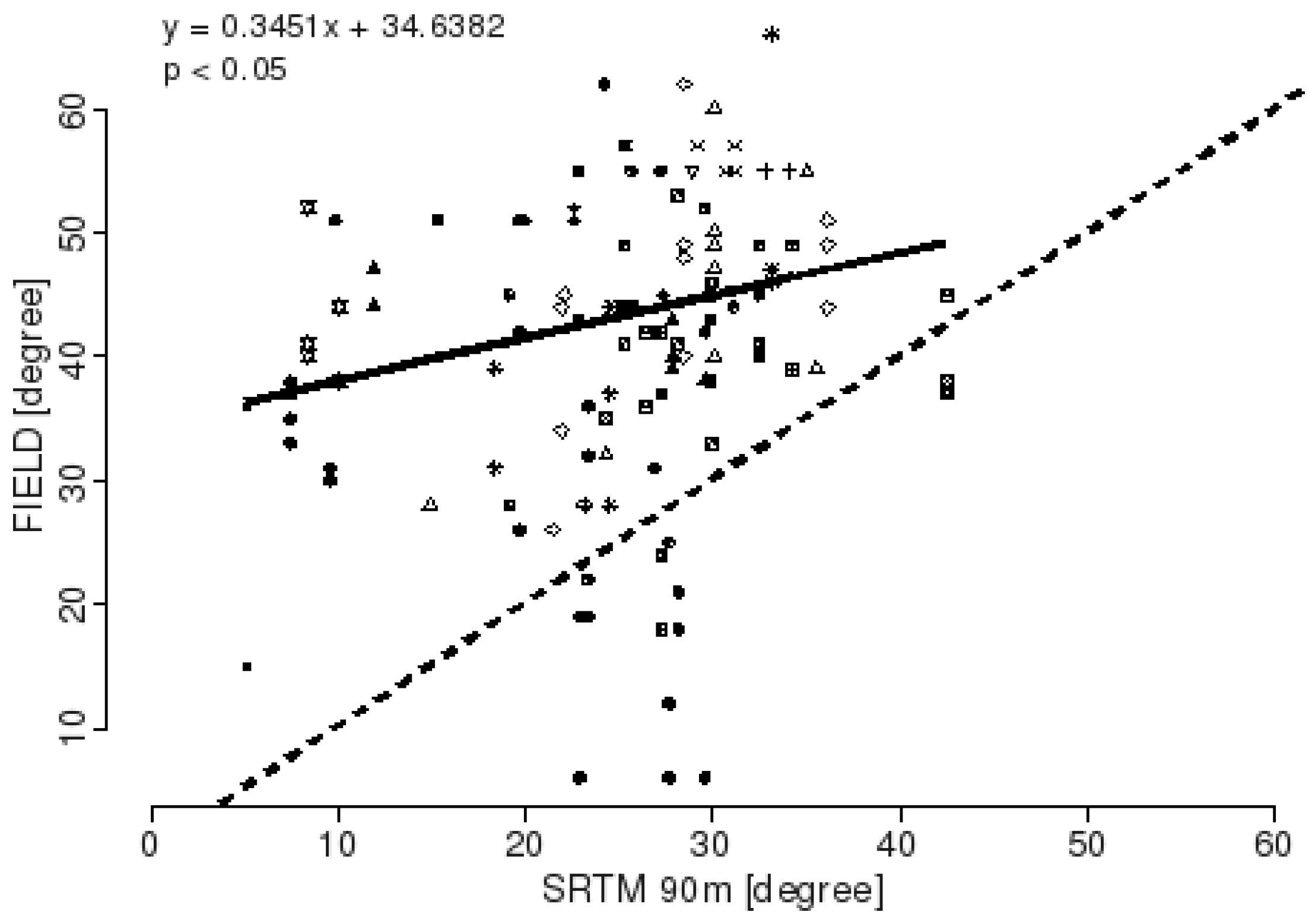
Figure 8. Correlation between slope data from SRTM 90m DEM and field measurements. Different symbols denote data collected along different transects (continuous thick line is the regression line).
Remotesensing 02 01941 g008

4. Discussion

The results show that there are significant differences between the DEMs and the topographical parameters derived from them. These differences clearly emphasize that the choice of the DEM has an important influence on the erosion relevant topographical parameters and, consequently, on the expected soil erosion modeling results.

4.1. DEM Elevation

The results for the DEM vertical accuracy appear to be highly differentiated. The averaged absolute height above the sea level was significantly lower in ASTER DEMs as compared to the TOPO and SRTM DEMs. Many studies [23,35] have validated this underestimation of ASTER for mountainous regions suggesting this to be a concern when using ASTER data. Terrain discretization of SRTM from 90 m to 20 m and terrain smoothing of ASTER from 15 m to 20 m resolutions do not produce any large effects on the DEM elevations.
Analysis of the deviations indicates that the underestimation in ASTER was higher in rougher terrain than the other DEMs and that the flat areas and valleys were overestimated. These results are similar to the large errors observed by [36] in ASTER DEM at steep cliffs and deep valleys. ASTER underestimation was also found to be more pronounced on the western aspect than in the east which again conforms to the findings of [36] that the western exposed slopes were too low. They [36] however observed eastern slopes to be overestimated while in our case they were underestimated although this underestimation was not as high as in the western aspect.
The absolute low elevations of ASTER DEM may be a result of the smoothing procedure in stereocorrelation [37]. The systematic errors in ASTER DEM may be explained by the difficulties of stereocorrelation in forested canopy [36,38] and by the effects of mountainous relief on the performance of stereoscopic DEMs.
Besides the systematic errors, the ASTER model reveals important scattered deviation when compared to the other models and is observed to vary in a similar manner from both TOPO and SRTM DEMs. The roughness of a DEM depends on its resolution and standard deviation of elevation which is a measure of local relief at a fine scale while at a coarser scale this attribute measures the roughness of the landscape [39]. ASTER, being the highest spatial resolution DEM, should have accounted for the roughest terrain features considering the complexity of the actual terrain. The TOPO model on the other hand on interpolation from the contour lines has a smoothing effect on the local peak features. The results however make it apparent that TOPO and SRTM account for higher roughness while ASTER differs from both in having a much lower surface roughness. Interestingly, despite its apparent lesser roughness, the ASTER models showed the presence of many false peaks (pyramid like structures), the presence of which could not be ascertained during the extensive field surveys.
For mountainous areas many studies have been conducted to compare the vertical accuracy of different DEMs [29,40] but, to our knowledge, only a few instances of DEM accuracy assessment using field data are available [41]. When we look at the absolute differences between the DEMs, it is quite evident that the average differences between ASTER-TOPO and ASTER-SRTM DEMs are quite high. These differences are however quite consistent with recent findings which have reported a RMSE of elevation differences between 15 m to 70 m depending on the topographical conditions [23,40,42].
SRTM and TOPO models appear to show similarities regarding the extent of local deviations but these deviations were the lowest for SRTM when compared to the field measurements. All the DEMs show higher RMSE in comparison to the field values than those reported by [2] from another mountainous area. Although no studies were found which made such comparison for extreme mountainous areas, these high RMSE values may be considered to be a result of the highly complex topography which is a characteristic of the Himalayan terrain.
Field control shows none of the DEMs to be an accurate representation of the watershed terrain, but the SRTM DEM with the lowest RMSE compared to field measurements can be considered to have the highest field representability. The TOPO DEM with the lowest mean differences from the field elevations appears to be closer to SRTM DEM. The ASTER DEM on the other hand accounted for the highest average differences and the highest RMSE compared to the field elevations suggesting its reduced field representability.

4.2. Slope and Aspect

Slope is a primary topographical attribute and is determined from the derivatives of the topographical surface. The slope maps computed from the different DEMs showed significant variations. The steepest slopes tended to disappear as the DEM resolution increased from 15-m (ASTER) to 90-m (SRTM). ASTER DEM when interpolated from 15-m to 20-m produced similar smoothing of slopes while the SRTM DEM when discretized from 90-m to 20-m resolution tended to produce steeper slopes. Similarly, the lowest slopes tended to increase in frequency as the DEM resolution became finer. All these observations are along expected lines where the smoothing effect results in an averaging of slopes and agree with the results reported by [2,43,44,45]. The higher resolution ASTER 15m however shows lower average slope compared to the TOPO 20m, which appears to be inconsistent with the predicted trend. The ASTER DEM also accounts for the highest percentage of flat and less steep areas (about 20 percent of the area has slope below 10 degrees) compared to the TOPO DEM (8 percent) and SRTM DEM (11 percent) which have relatively lower frequency of flat and less steep areas. The overestimation of flat and near flat as well as steep areas by the ASTER DEM is in agreement with the observations made by [42] and may be attributed to the errors in stereocorrelation which may be more prominent in forested areas due, in part, to a lack of clearly defined features [46]. The presence of shaded areas and extremely steep rock walls may have further reduced the accuracy of the ASTER stereocorrelation process and consequently the extracted DEM and the DEM derived parameters.
Another general trend observed was that all the DEMs produced lower minimum slopes and less steep mean slopes as compared to the field measurements. General smoothing of DEMs can result in removing the extremes of both flat and steep slopes, but the systematic underestimation of slopes by all the DEMs appears illogical when the slope is observed as a two dimensional attribute. Although difficult to explain, the complex three dimensional mountainous terrain where shape of the slopes in horizontal and vertical direction (curvature) changes over small distances and account for the lateral roughness of the slopes might be responsible for this behavior of all the DEMs.
Aspect, although not a direct erosion relevant parameter, plays a very important role in delineating the flowlines and subsequently the flow accumulation in sub-catchments. All the DEMs used in this study were observed to underestimate the north facing slopes for all 152 field locations (northern aspect). The study watershed is an elongated watershed and is positioned lengthwise in the north-south direction with the outlet towards the south. Hence, in a hypothetical scenario, with extreme smoothing and coarsening of the DEM resolution, one can expect the absence of the northern aspect. But the inability of the DEMs to account for these slopes, as well as the presence of these slopes in the field measurements suggests the limitation of the DEMs in representing the lateral roughness and the fine scale features of the terrain.
Because of the strong deviations between the DEM derived slopes, linear regression was used to observe the relationship between the DEM and the field measured slopes. Linear mixed model approach, the Mixed Procedure [47] was adopted instead of standard linear regression to take into account the possible clustering effect of sampling transects on the observations. The field measured slope was the response variable while the DEM slope constituted the explanatory variable and the transect number constituted the random effect. The comparisons with simple linear models show no significant effect of transects on the slope values. The regression models also reaffirmed the previous observation that the SRTM DEM was the closest to the field measurements with SRTM 90m showing the most significant relationship with the field slopes. The linear relationship between SRTM 90m and field slope values (Figure 7) shows the intercept to be 34.64 degrees while the slope of the regression line is 0.35 percent. The high percentage of flat and low slope areas in the DEM, which may be the artifacts of the smoothing procedure, may be responsible for the production of this bias in the DEM, thereby making them unreliable at hillslope and finer scales. Thus SRTM which, among the tested DEMs, is the closest to the field values, still lacks the adequate field representability to account for local terraces, relatively flat valley bottoms and ridges, as is the case with the other tested DEMs as well.

4.3. RUSLE LS Factor

Although the slope lengths in mountainous terrain have not been significantly researched [48], it has been reported, by McCool et al. in [31], that the slope lengths in general did not exceed 300 m. In our study watershed, however, we observed maximum slope length of 310 m in the field while the DEM calculated slope lengths were even higher (Figure 8). The field slope lengths used in this study, although not very precise, can be considered to be relatively reliable considering the magnitude of differences in slope lengths obtained using different sources. These field slope lengths clearly highlight the significant difference of both field and ASTER generated slope lengths from those derived from the other DEMs.
TOPO and SRTM DEMs produced the highest absolute slope lengths which can be explained by smoothing effect of the DEM generation procedure on topographical surfaces wherein the terrain generalization results in the disappearance of micro topographical features [43,44] thereby lengthening the flow paths. The ASTER DEMs on the other hand produced smaller slope lengths which are significantly lower than the TOPO and SRTM slope lengths and are closer to the field measured slope lengths. This random improvement of ASTER derived slope lengths may be a result of artifacts in high resolution DEMs which may tend to produce errors in the calculation of slope lengths. Similar observation was made by [17] when they observed errors in upslope area calculations resulting in lower erosion rates due to irregularities in the less smooth high resolution ASTER DEM.
In contrast, significantly similar underestimation of slope steepness values was observed for all the DEMs. The RUSLE LS factor values obtained using these DEM generated parameters appear to be more sensitive to slope lengths than to the slope steepness, which is in contrast to the observations made by [34]. This sensitivity may be attributed to almost identical mean slope steepness of all the DEMs. The LS factor values obtained from the ASTER DEMs, although closer to the field measured LS factor values in magnitude, may not be considered to be accurate representation of the field topography. This result appears to be a random improvement rather than being a higher field relevance of ASTER DEMs because the slope lengths produced by the ASTER DEMs, though significantly lower than the other DEMs, are not based on a realistic surface topography but may be the result of artifacts in the high resolution DEMs.

5. Conclusions

Uncertainties associated with the DEM derived topographical parameters used for soil erosion modeling, especially in mountainous areas with insufficient data availability, can tend to reduce the reliability of the predicted erosion estimates which can adversely affect land-use planning activities. The uncertainty regarding the input DEM data was attributed by [14] to be one of the reasons for LISEM soil erosion model being unsuccessful in simulating erosion in the catchment.
In this study, DEMs from different sources and different resolutions were analyzed for their relative accuracy of the derived topographical parameters and their reliability compared with the field measurements. The results indicate that all the DEMs differed considerably from each other as well as from the field measurements for all the tested parameters.
The highest resolution ASTER DEM was found to be the least realistic among all the tested DEMs. The DEM as well as the topographical parameters derived from it were found to differ the most from all the other DEMs and from the field measurements, suggesting that stereocorrelation based DEMs should be used carefully due to inherent difficulties of stereocorrelation for mountainous terrain and under forest canopy. The DEM coincidently produced the lowest LS factor values which were closest to the field LS factors, but these seemingly good results were not based on realistic surface characteristics. Due to the overall poor performance of ASTER based DEM, it is not recommended as the DEM of choice for this watershed.
TOPO DEM, which theoretically is more detailed than the SRTM DEM, clearly did not produce an improved representation of the watershed topography. This leads to the conclusion that, at the presently available scale of topographical maps for the Himalayan region (i.e., 1: 50,000 scale), the time and cost intensive procedure of digitizing contour lines to produce a topographical DEM does not provide an improved output compared to the freely available SRTM DEM. The production of a topographical DEM can be justified if a finer scale topographical map were available.
SRTM DEM was observed to be the most reliable of the tested DEMs and, considering the open source availability and the least processing cost and processing time requirement of this DEM, it can be considered to be the most suitable among the tested DEMs for the study watershed.

Acknowledgements

We wish to extent thanks to the German Academic Exchange Service (DAAD) for sponsoring the Ph.D. project. Thanks are due to Ernst E. Hildebrand, Institute of Soil Science and Forest Nutrition, Freiburg University for making this research possible by providing his worthy supervision. S. P. S. Kushwaha and Suresh Kumar, Indian Institute of Remote Sensing (IIRS), Dehradun, India, are duly acknowledged for their support during the field surveys. Rudi Hessel, Alterra, Wageningen University is duly thanked for his worthy comments for improving the manuscript.

References

  1. Lal, R. Soil degradation by erosion. Land Degrad. Dev. 2001, 12, 519–539. [Google Scholar] [CrossRef]
  2. Zhang, J.X.; Chang, K.-T.; Wu, J.Q. Effects of DEM resolution and source on soil erosion modelling: A case study using the WEPP model. Int. J. Geogr. Inf. Sci. 2008, 22, 925–942. [Google Scholar] [CrossRef]
  3. Sefercik, U.; Jacobsen, K.; Oruc, M.; Marangoz, A. Comparison of SPOT, SRTM and ASTER DEMs. In Proceedings of the ISPRS Workshop on High-Resolution Earth Imaging for Geospatial Information, Hannover, Germany, 29 May–1 June 2007.
  4. Rabus, B.; Eineder, M.; Roth, A.; Bamler, R. The shuttle radar topography mission—A new class of digital elevation models acquired by spaceborne radar. ISPRS J. Photogramm. Remote Sens. 2003, 57, 241–262. [Google Scholar] [CrossRef]
  5. Abrams, M. ASTER: Data products for the high spatial resolution imager on NASA’s Terra platform. Int. J. Remote Sens. 2000, 21, 847–853. [Google Scholar] [CrossRef]
  6. Eckholm, E. The deterioration of mountain environments. Science 1975, 189, 764–770. [Google Scholar] [CrossRef] [PubMed]
  7. Reiger, H.C. Man versus mountain: The destruction of the Himalayan ecosystem. In The Himalaya: Aspects of Change; Lal, J.S., Moddie, A.D., Eds.; Oxford University Press: New Delhi, India, 1981; pp. 351–376. [Google Scholar]
  8. Myers, N. Environmental repercussions of deforestation in the Himalayas. J. World Forest Resource Manag. 1986, 2, 63–72. [Google Scholar]
  9. Shrestha, D.P. Assessment of soil erosion in the Nepalese Himalaya, a case study in Likhu Khola valley, Middle Mountain region. In Land Husbandry; Oxford & IBH Publishing Co. Pvt. Ltd.: New Delhi, India, 1997; Volume 2, pp. 59–80. [Google Scholar]
  10. Morgan, R.P.C.; Morgan, D.D.V.; Finney, H.J. A predictive model for the assessment of soil erosion risk. J. Agr. Eng. Res. 1984, 30, 245–253. [Google Scholar] [CrossRef]
  11. Kumar, S.; Sharma, S. Soil erosion risk assessment based on MMF model using remote sensing and GIS. Hydrology J. 2005, 28, 47–58. [Google Scholar]
  12. Jain, S.K.; Kumar, S.; Varghese, J. Estimation of soil erosion for a Himalayan watershed using GIS technique. Water Resour. Manag. 2001, 15, 41–54. [Google Scholar] [CrossRef]
  13. Wischmeier, W.H.; Smith, D.D. Predicting Rainfall Erosion Losses—A Guide to Conservation Planning; Agricultural Handbook No. 537; U.S. Department of Agriculture, Agricultural Research Service: Washington, DC, USA, 1978.
  14. Hessel, R.; Gupta, M.K.; Datta, P.S.; Gelderman, E. Application of the LISEM soil erosion model to a forested catchment in the Indian Himalayas. Int. J. Ecol. Environ. Sci. 2007, 33, 129–142. [Google Scholar]
  15. De Roo, A.P.J.; Wesseling, C.G.; Ritsema, C.J. LISEM: A single-event physically based hydrological and soil erosion model for drainage basins. I: Theory, input and output. Hydrol. Process. 1996, 10, 1107–1117. [Google Scholar] [CrossRef]
  16. Jetten, V.; De Roo, A.P.J. Spatial analysis of erosion conservation measures with LISEM. In Landscape Erosion and Evolution Modeling; Harmon, R., Doe, W.W., Eds.; Kluwer Academic/Plenum: New York, NY, USA, 2001; pp. 429–445. [Google Scholar]
  17. de Vente, J.; Poesen, J.; Govers, G.; Boix-Fayos, C. The implications of data selection for regional erosion and sediment yield modelling. Earth Surf. Process. Landf. 2009, 34, 1994–2007. [Google Scholar] [CrossRef]
  18. Jenson, S.K. Applications of hydrological information automatically extracted from digital elevation models. Hydrol. Process. 1991, 5, 31–44. [Google Scholar] [CrossRef]
  19. Wolock, D.M.; McCabe, G. Differences in topographic characteristics computed from 100- and 1000-m resolution digital elevation model data. Hydrol. Process. 2000, 14, 987–1002. [Google Scholar] [CrossRef]
  20. Raina, A.K.; Gupta, M.K. Geology and geomorphology of Arnigad watershed in Lesser Himalayas, Missoorie Forest Division, Uttaranchal. Ann. Forest. 2006, 14, 255–267. [Google Scholar]
  21. Sharma, S.D.; Singh, B.R.; Sitaula, B.; Gupta, M.K. Influence of land cover on soil properties in a watershed in Lesser Himalayas. Ann. Forest. 2006, 14, 16–34. [Google Scholar]
  22. Chandra, R.; Soni, P.; Yadav, V. Fuelwood, fodder and livestock status in a Himalayan watershed in Mussoorie Hills (Uttarakhand), India. Indian Forest. 2008, 134, 894–905. [Google Scholar]
  23. Hirano, A.; Welch, R.; Lang, H. Mapping from ASTER stereo image data: DEM validation and accuracy assessment. ISPRS J. Photogramm. Remote Sens. 2003, 57, 356–370. [Google Scholar] [CrossRef]
  24. USGS. Shuttle Radar Topography Mission, 3 Arc Second Scene SRTM_ff03_p146r039, Filled Finished-A; Global Land Cover Facility, University of Maryland: College Park, MD, USA, February 2000.
  25. Mitasova, H.; Hofierka, J. Interpolation by regularized spline with tension: II. Application to terrain modeling and surface geometry analysis. Math. Geol. 1993, 25, 657–669. [Google Scholar] [CrossRef]
  26. Mitasova, H.; Mitas, L. Interpolation by regularised spline with tension: I. Theory and implementation. Math. Geol. 1993, 25, 641–655. [Google Scholar] [CrossRef]
  27. Jenson, S.K.; Domingue, J.O. Extracting topographic structure from digital elevation data for geographic information system analysis. Photogramm. Eng. Remote Sensing 1988, 54, 1593–1600. [Google Scholar]
  28. Neteler, M.; Mitasova, H. Open Source GIS—A GRASS GIS Approach, 3rd ed.; Springer: New York, NY, USA, 2007; Volume 773. [Google Scholar]
  29. Nikolakopoulos, K.G.; Kamaratakis, E.K.; Chrysoulakis, N. SRTM vs ASTER elevation products. Comparison for two regions in Crete, Greece. Int. J. Remote Sens. 2006, 27, 4819–4838. [Google Scholar] [CrossRef]
  30. Horn, B. Hill shading and the reflectance map. Proc. IEEE 1981, 69, 14–47. [Google Scholar] [CrossRef]
  31. Renard, K.G.; Foster, G.R.; Weesies, G.A.; McCool, D.K.; Yoder, D.C. Predicting Soil Erosion by Water: A Guide to Conservation Planning with the Revised Universal Soil Loss Equation (RUSLE); Agriculture Handbook No. 703; US Department of Agriculture, Agricultural Research Service: Washington, DC, USA, 1997.
  32. Renard, K.G.; Ferreira, V.A. RUSLE model description and database sensitivity. J. Environ. Qual. 1993, 22, 458–466. [Google Scholar] [CrossRef]
  33. McCool, D.K.; Foster, G.R.; Mutchler, C.K.; Meyer, L.D. Revised slope length factor for the Universal Soil Loss Equation. Trans. ASAE 1989, 32, 1571–1576. [Google Scholar] [CrossRef]
  34. McCool, D.K.; Brown, C.L.; Foster, G.R.; Mutchler, C.K.; Meyer, L.D. Revised slope steepness factor for the Universal Soil Loss Equation. Trans. ASAE 1987, 30, 1387–1396. [Google Scholar] [CrossRef]
  35. Eckert, S.; Kellenberger, T. Qualitätanalyse automatisch generierter digitaler Geländenodelle aus ASTER Daten. In Proceedings of Wissenschaftlich-Technische Jahrestagung der Deutschen Gesellschaft für Photogrammetrie und Fernerkundung, Neubrandenburg, Germany; 2002; pp. 337–341. [Google Scholar]
  36. Eckert, S.; Kellenberger, T.; Itten, K. Accuracy assessment of automatically derived digital elevation models from aster data in mountainous terrain. Int. J. Remote Sens. 2005, 26, 1943–1957. [Google Scholar] [CrossRef]
  37. Kamp, U.; Bolch, T.; Olsenholler, J. Geomorphometry of Cerro Sillajhuay (Andes, Chile/Bolivia): Comparison of digital elevation models (DEMs) from ASTER remote sensing data and contour maps. Geocarto Int. 2005, 20, 23–33. [Google Scholar] [CrossRef]
  38. Toutin, Th. 3D topographic mapping with ASTER stereo data in rugged topography. IEEE Trans. Geosci. Remote Sens. 2002, 40, 2241–2247. [Google Scholar] [CrossRef]
  39. Gallant, J.C.; Wilson, J.P. Primary topographic attributes. In Terrain Analysis: Principles and Applications; Wilson, J.P., Gallant, J.C., Eds.; John Wiley and Sons: New York, NY, USA, 2000; pp. 51–85. [Google Scholar]
  40. Huggel, C.; Schneider, D.; Miranda, P.J.; Granados, H.D.; Kääb, A. Evaluation of ASTER and SRTM DEM data for lahar modelling: A case study on lahars from Popocatépetl volcano, Mexico. J. Volcan. Geotherm. Res. 2008, 170, 99–110. [Google Scholar] [CrossRef] [Green Version]
  41. Gorokhovich, Y.; Voustianiouk, A. Accuracy assessment of the processed SRTM-based elevation data by CGIAR using field data from USA and Thailand and its relation to the terrain characteristics. Remote Sens. Environ. 2006, 104, 409–415. [Google Scholar] [CrossRef]
  42. Kääb, A. Combination of SRTM3 and repeat ASTER data for deriving alpine glacier flow velocities in the Bhutan Himalaya. Remote Sens. Environ. 2005, 94, 463–474. [Google Scholar] [CrossRef]
  43. Wolock, D.M.; Price, C.V. Effects of digital elevation map scale and data resolution on a topographically-based watershed model. Water Resour. Res. 1994, 30, 3041–3052. [Google Scholar] [CrossRef]
  44. Zhang, W.H.; Montgomery, D.R. Digital elevation model grid size, landscape representation, and hydrologic simulations. Water Resour. Res. 1994, 30, 1019–1028. [Google Scholar] [CrossRef]
  45. Kienzle, S. The effect of DEM raster resolution on first order, second order and compound terrain derivatives. Trans. GIS 2004, 8, 83–111. [Google Scholar] [CrossRef]
  46. Bolstad, P.V.; Stowe, T. An evaluation of DEM Accuracy: Elevation, slope, and aspect. Photogramm. Eng. Remote Sensing 1994, 60, 1327–1332. [Google Scholar]
  47. SAS Institute Inc. SAS/STAT Software Version 9.1; SAS Institute Inc.: Cary, NC, USA, 2008. [Google Scholar]
  48. van Remortel, R.D.; Hamilton, M.E.; Hickey, R.J. Estimating the LS factor for RUSLE through iterative slope length processing of digital elevation data within ArcInfo grid. Cartography 2001, 30, 27–35. [Google Scholar] [CrossRef]