Article

Waveform Optimization for Enhancing the Performance of a Scanning Imaging Radar Utilizing a Terahertz Metamaterial Antenna

1
College of Electronic Science and Technology, National University of Defense Technology, Changsha 410073, China
2
Terahertz Science and Technology Research Center, University of Electronic Science and Technology of China, Chengdu 610054, China
*
Author to whom correspondence should be addressed.
Remote Sens. 2025, 17(9), 1595; https://doi.org/10.3390/rs17091595
Submission received: 21 March 2025 / Revised: 16 April 2025 / Accepted: 27 April 2025 / Published: 30 April 2025

Abstract

:
A scanning radar based on terahertz metamaterial phased array (TMPA) is a novel system for forward-looking imaging. In this paper, a waveform optimization method based on random hopping frequency (RHF) and amplitude modulation is proposed to improve the performance of TMPA scanning imaging radars. The RHF signal waveform is employed to reduce the sidelobes of the range ambiguity function for improving the measurement accuracy in range, while the amplitude modulation is applied to optimize the convolution matrix composed of samples of the antenna pattern, thereby enhancing the azimuth super-resolution. Interestingly, amplitude modulation for waveform design is based on the criterion of minimizing the residual between the real echo and the reconstructed echo with the limited transmission power, without any assumptions about the statistical distribution of target scattering. The effectiveness of the proposed waveform optimization method for enhancing the performance of a TMPA scanning imaging radar is verified through simulations and experiments.

1. Introduction

The terahertz (THz) wave lies between the microwave and infrared frequency ranges, with a frequency range of 0.1 THz to 10 THz [1]. A radar system that works in THz bands has many unique properties [2,3,4]. It has a higher resolution compared with microwave radars [5,6] and stronger penetrability relative to LiDAR systems [7,8]. Therefore, THz radar imaging technology has gained significant attention within the research community. Particularly, THz radar forward-looking imaging technology has been widely explored by researchers due to its immense potential in various applications, including precision guidance, terrain mapping, autonomous landing, and automatic driving [9,10,11,12]. Although bistatic SAR and forward-looking array SAR are capable of forward-looking imaging, they face challenges related to synchronization and limited platform space, respectively [13,14,15,16]. Furthermore, a real-aperture scanning radar can also achieve forward-looking imaging, but it is accompanied by high system complexity and power consumption [17,18,19]. Consequently, there is an urgent requirement for advanced antenna arrays and radar systems that possess both cost-effectiveness and energy efficiency, thereby promoting the progression of THz radar forward-looking imaging technology.
In recent years, artificial composites fabricated from subwavelength patterned structures, referred to as metamaterials, have garnered substantial research interest due to their cost-effectiveness, low power consumption, simplicity, and ability to manipulate electromagnetic waves [20,21,22,23,24]. One such metamaterial is the 1-bit phase-modulation programmable metamaterial, where each unit independently introduces a 1-bit phase delay (0° or 180°) to the incident THz wave, similar to a 1-bit phased-array antenna. Due to its outstanding performance, the THz metamaterial phased array (TMPA) antenna is emerging as a highly promising alternative to traditional real-aperture scanning imaging radar antennas. Consequently, research on scanning imaging radars based on TMPA is increasingly being pursued [25,26,27,28,29]. Despite high-distance resolution being achieved through linear frequency-modulation signals and pulse compression, the ambiguity function exhibits a standard sinusoidal shape, with a main lobe-to-sidelobe ratio of approximately 13 dB, which presents challenges for engineering applications. Moreover, as far as we know, there are no studies on azimuth super-resolution imaging by scanning radars based on a TMPA antenna. Given that the azimuth echo is generated by the convolution of the antenna radiation pattern and the target scattering coefficient, super-resolution in azimuth can be obtained via deconvolution methods [30,31,32]. However, deconvolution is an ill-posed problem, and current super-resolution algorithms struggle with inverse problems when dealing with a fixed measurement matrix.
In order to further improve the performance of TMPA scanning imaging radars, this paper presents a waveform optimization method that employs random hopping frequency (RHF) and amplitude modulation. By leveraging RHF signals, the proposed approach reduces the intercept probability and enhances anti-interference capabilities of the radar system while simultaneously reducing the sampling rate. Additionally, the optimization of the frequency set of the RHF signals effectively suppresses the sidelobes of the range ambiguity function, enhancing the range resolution capability. Building upon this foundation, the amplitude of the RHF signal is modulated to optimize the convolution matrix derived from the antenna pattern and to improve the azimuth super-resolution. Simulation and experimental results demonstrate that the performance of a TMPA scanning imaging radar can be effectively enhanced through the waveform optimization method combined with RHF and amplitude modulation. The main contributions of this article are as follows:
(1)
The super-resolution imaging capability of a scanning radar is studied by using an electronically controlled TMPA antenna for the first time.
(2)
The proposed waveform optimization method enhances both the range and the azimuth resolution by employing RHF and amplitude modulation simultaneously, thereby improving the imaging performance of the scanning radar.
(3)
In contrast to conventional waveform optimization techniques, the proposed method utilizes the minimization of residuals between real and reconstructed echoes as its criterion, eliminating the need to assume that the target scattering characteristics follow a Gaussian distribution, which leads to a wider applicability.
The remainder of this article is organized as follows: In Section 2, the system architecture of the TMPA scanning imaging radar is presented. In Section 3, a waveform optimization method based on RHF and amplitude modulation is derived to improve the performance of the TMPA scanning imaging radar. In Section 4, the effectiveness of the proposed waveform optimization method is verified using both simulation and experimental data. Section 5 presents a concise conclusion.

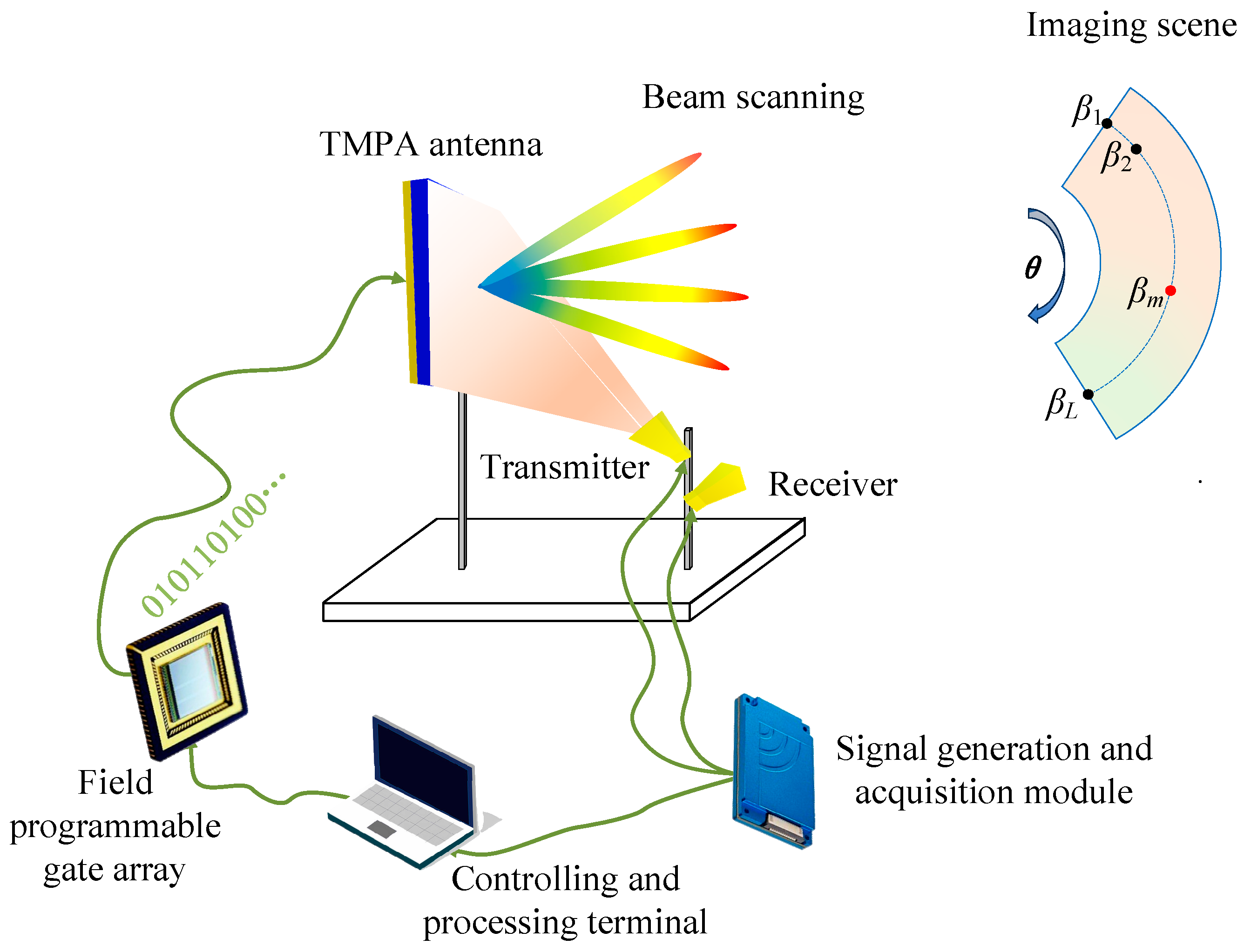
2. System Architecture of the TMPA Scanning Imaging Radar

According to the theory of the planar reflectarray, the far-field radiation pattern of a TMPA antenna under spherical incident waves can be expressed as [33,34]
F ( θ , φ ) = u = 1 U v = 1 V e j ( k ( x u sin θ cos φ + y v sin θ cos φ R u , v ) + ϕ u , v )
where θ and φ are the elevation angle and azimuth angle, respectively. xu and yv represent the location of the unit cell in both x and y directions, and k is the wavenumber. Ru,vdenotes the distance between the feeding source and each element. Φu,v is the compensation phase of the unit cell located at the u-th row and v-th column, which is given by
ϕ u , v = k ( R u , v sin θ ( x u cos φ + y v sin φ ) )
Considering the compensation phase quantified with one bit, Φu,v is selected from among 0 and π. It can be seen from Equation (1) that beam scanning can be realized by phase compensation of the TMPA antenna.
The scanning imaging system based on the TMPA antenna is illustrated in Figure 1, and it mainly consists of the controlling and processing terminal, field programmable gate array (FPGA), and the signal generation and acquisition module. The THz wave generated by the signal generation and acquisition module is first transmitted to the TMPA antenna. The FPGA then controls the encoding state of the TMPA antenna, modulating the wavefront of the terahertz waves to achieve beam steering. The deflected beam is applied to scan the whole imaging scene, and the reflected wave can be collected by the receiving antenna. The target in the imaging area is reconstructed from the echo signal using the controlling and processing terminal. It should be pointed out that in the same range bin, the imaging scene in azimuth is sampled into L angles βm, where m = 1, …, L.

3. Waveform Optimization Method

To suppress the range ambiguity and to enhance the performance of anti-jamming, the RHF signal composed of N monotone frequency pulses is transmitted for each scanning angle. Supposing that the monotone frequency is randomly distributed within a given bandwidth B that is divided into M parts, the frequency interval ∆f is equal to B/M. Therefore, the signal emitted by the transmitter can be described as [35]
s ( t ) = n = 0 N 1 rect t n T r T p e j 2 π ( f c + c n Δ f ) ( t n T r ) .
where Tr and Tp are the pulse repetition period and the pulsewidth, respectively. fc denotes the carrier frequency. t is fast time, which is related to the range information. cn is the frequency hopping coefficient and is a randomly selected integer between 0 and M that satisfies max{cn} = M and min{cn} = 0. rect(x) is a rectangular function defined by
rect x = 1 , 0 x < 1 0 , others .
For convenience, given a point target whose range and azimuth with respect to the metamaterial antenna is R and βm, respectively, the echo can be written as
s r ( t ) = σ h ( θ β m ) s ( t τ ) .
where σ is the scattering coefficient of the target and τ = 2R/c is the echo delay, in which c is the speed of light. h(θ − βm) represents the antenna pattern. The echo signal is processed by the matching filter, and the result (that is, the ambiguity function) can be described as
χ ( τ ) = + s ( t ) s r * ( t ) d t = σ h ( θ β m ) + n = 0 N 1 rect t n T r T p e j 2 π ( f c + c n Δ f ) ( t n T r ) m = 0 N 1 rect t τ m T r T p e j 2 π ( f c + c n Δ f ) ( t τ m T r ) d t = σ h ( θ β m ) + n = 0 N 1 m = 0 N 1 e j 2 π ( f c + c n Δ f ) ( t n T r ) e j 2 π ( f c + c n Δ f ) ( t τ m T r ) rect t n T r T p rect t τ m T r T p d t
Let p = m − n; when p is equal to 0, the ambiguity function represents the autocorrelation function (i.e., the center range ambiguity function) for each pulse, which can be simplified as follows:
χ ( τ ) = σ h ( θ β m ) + n = 0 N 1 n = 0 N 1 e j 2 π ( f c + c n Δ f ) ( t n T r ) e j 2 π ( f c + c n Δ f ) ( t τ n T r ) rect t n T r T p rect t τ n T r T p d t = σ h ( θ β m ) + n = 0 N 1 e j 2 π ( f c + c n Δ f ) τ rect t n T r T p rect t τ n T r T p d t = σ h ( θ β m ) ( ( T p | τ | ) n = 0 N 1 e j 2 π ( f c + c n Δ f ) τ ) , | τ | T p
Equation (7) suggests that the range ambiguity function is only related to the time delay τ and the frequency set of the RHF signal when the scanning angle is fixed, while the transmission sequence of the pulse frequency has no influence on that. Once the frequency set of the RHF signal is selected, the range ambiguity function is also unique. As a result, the sidelobes of the range ambiguity function can be suppressed by optimizing the frequency combination using the Differential Evolution (DE) algorithm, thereby obtaining the high-range resolution. The specific optimization process is illustrated in Algorithm 1.
Algorithm 1. Algorithm of waveform optimization for enhancing the range resolution.
Step 1: Initialize the frequency set;
Step 2: Calculate the range ambiguity function according to Equation (7);
Step 3: Calculate the value of the objective function (the lowest sidelobe);
Step 4: Determine whether the terminational condition is met;
Step 5: If the conditions are not satisfied, update the frequency set via crossover, mutation, and so on;
Repeat step 2 to step 5 until the termination condition is met;
Output: The frequency set.
From Equation (5), it can be seen that the azimuth echo in one range unit is a convolution of the antenna radiation pattern and the target scattering coefficient and can be expressed in the form of matrix multiplication
y = H x + n .
where y = [y1, y2, …, yM]T denotes the echo signal with length M, x = [σ1, σ2, …, σL]T is the scattering coefficient at the grid point of the imaging scene, and n = [n1, n2, …, nM]T represents the noise, which follows a Gaussian distribution. Matrix H represents the measurements of the antenna pattern with size M × L and is written as
H = h ( θ 1 β 1 ) h ( θ 1 β 2 ) h ( θ 1 β L ) h ( θ 2 β 1 ) h ( θ 2 β 2 ) h ( θ 2 β L ) h ( θ M β 1 ) h ( θ M β 2 ) h ( θ M β L ) M × L
where M represents the number of azimuth scans conducted in the imaging scene, and L denotes the number of sampling points in the antenna pattern.
The azimuth super-resolution can be achieved by accurately recovering x using algorithms for solving the inverse problem, which break through the limitations of the real aperture. In order to further improve the azimuth resolution and enhance the performance of the imaging system, the amplitude of the transmitted signal in each scanning direction is modulated to optimize the convolution matrix H. This procedure is equivalent to multiplying a diagonal matrix on the left side of the convolution matrix H; thus, Equation (8) is rewritten as [36]
y 1 = α H x + n
where α represents a diagonal matrix whose diagonal elements are comprised of the amplitude of the RHF signal. A more accurate value of x can be obtained by changing the diagonal elements of matrix α under some constraints such that the amplitude of the transmitted signal is of finite value, i.e., the waveform optimization for enhancing the azimuth super-resolution.
According to the solution principle of the inverse problem, the precision of recovering x from y1 can be greatly improved by minimizing residuals. Therefore, the waveform optimization problem can be transformed into the minimization problem of the residual, and the objective function can be expressed as
arg min | | α H x e y 1 | | 2 + g ( x e ) s . t .   t r ( α α * ) < P
where the superscript “*” and tr(·) represent the conjugate and trace of the matrix, respectively. xe denotes the target scattering coefficient restructured by the super-resolution imaging algorithm at each iteration. In other words, the target scattering coefficient xe is recovered when given a diagonal matrix α. g(xe) is the prior information of the target, which can shorten the time needed to find the optimal waveform. If g(xe) is not available in advance, it can be removed. p is a fixed power value, which limits the transmitted power of the imaging system.
The above-mentioned objective function cannot be solved directly. Alternatively, the DE algorithm can also be employed to find the optimal diagonal matrix. This is because the DE algorithm is simple to implement, and it has the ability to find global optimal solutions rapidly when dealing with complex problems [37,38]. The detailed procedure for solving the optimization problem in Equation (11) is shown in Algorithm 2.
Algorithm 2. Algorithm of waveform optimization for enhancing the azimuth resolution.
Step 1: Initialize a diagonal matrix α;
Step 2: Update the matrix xe by solving Equation (10) with the CS algorithm;
Step 3: Calculate the value of the objective function according to (11);
Step 4: Determine whether the termination condition is met;
Step 5: If the conditions are not satisfied, update α via crossover, mutation and so on;
Repeat step 2 to step 5 until the termination condition is met;
Output: The optimal matrix α.
In summary, the optimal combination of the frequency set and amplitude of the transmitted signal can be found by solving the corresponding objective function with the DE algorithm; thus, the optimal waveform can be obtained. This optimal waveform can be mathematically expressed as
s ( t ) = A ( θ ) n = 0 N 1 rect t n T r T p e j 2 π ( f c + c n Δ f ) ( t n T r )
where A(θ) represents the amplitude of the transmitted signal, which changes with the scanning angle θ.

4. Simulations and Experimental Results

In this section, we describe the simulations and experiments performed to evaluate the effectiveness of the aforementioned waveform design methods. The performance of the imaging system was also compared under the waveform optimization and primary waveform conditions.

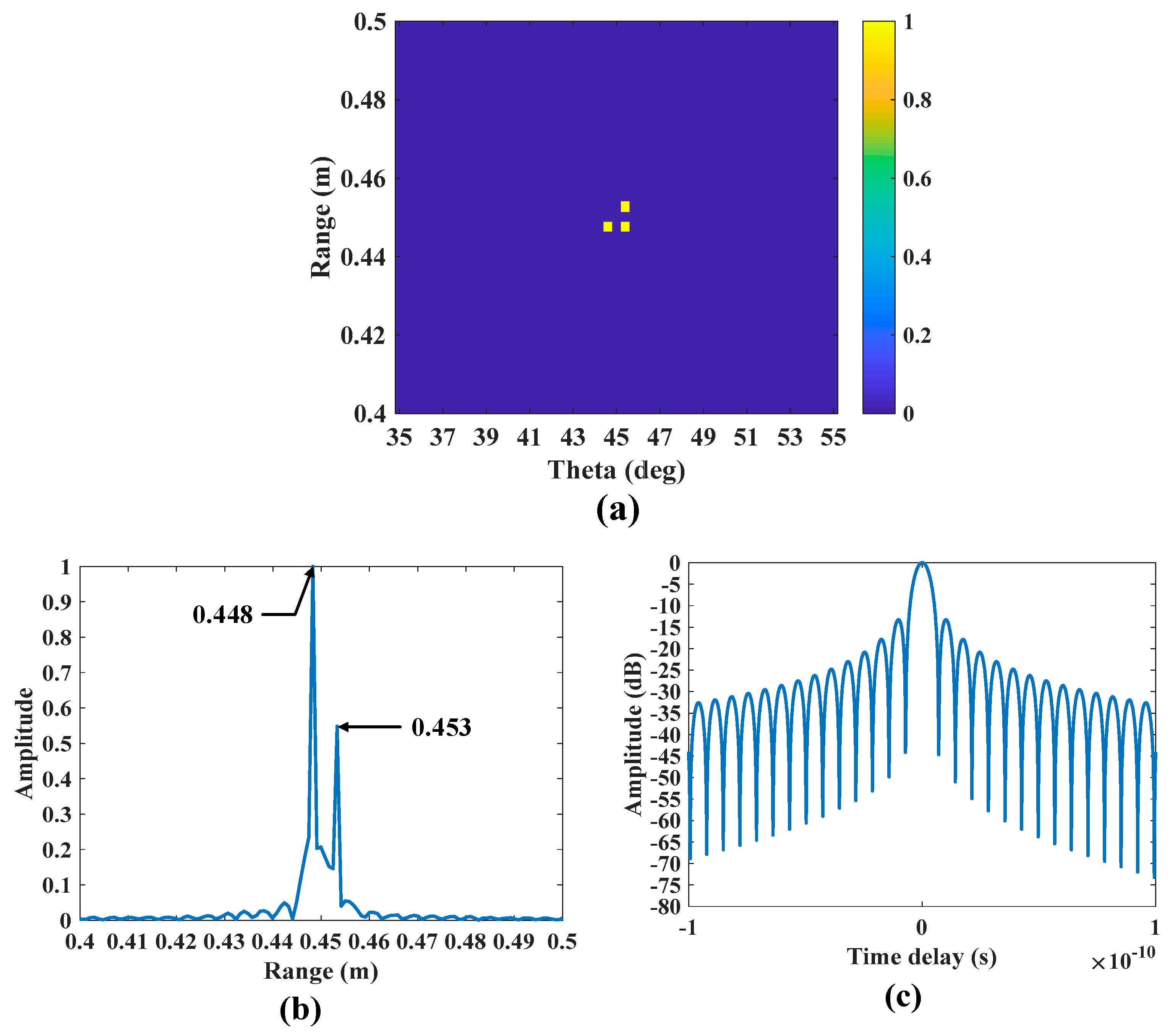
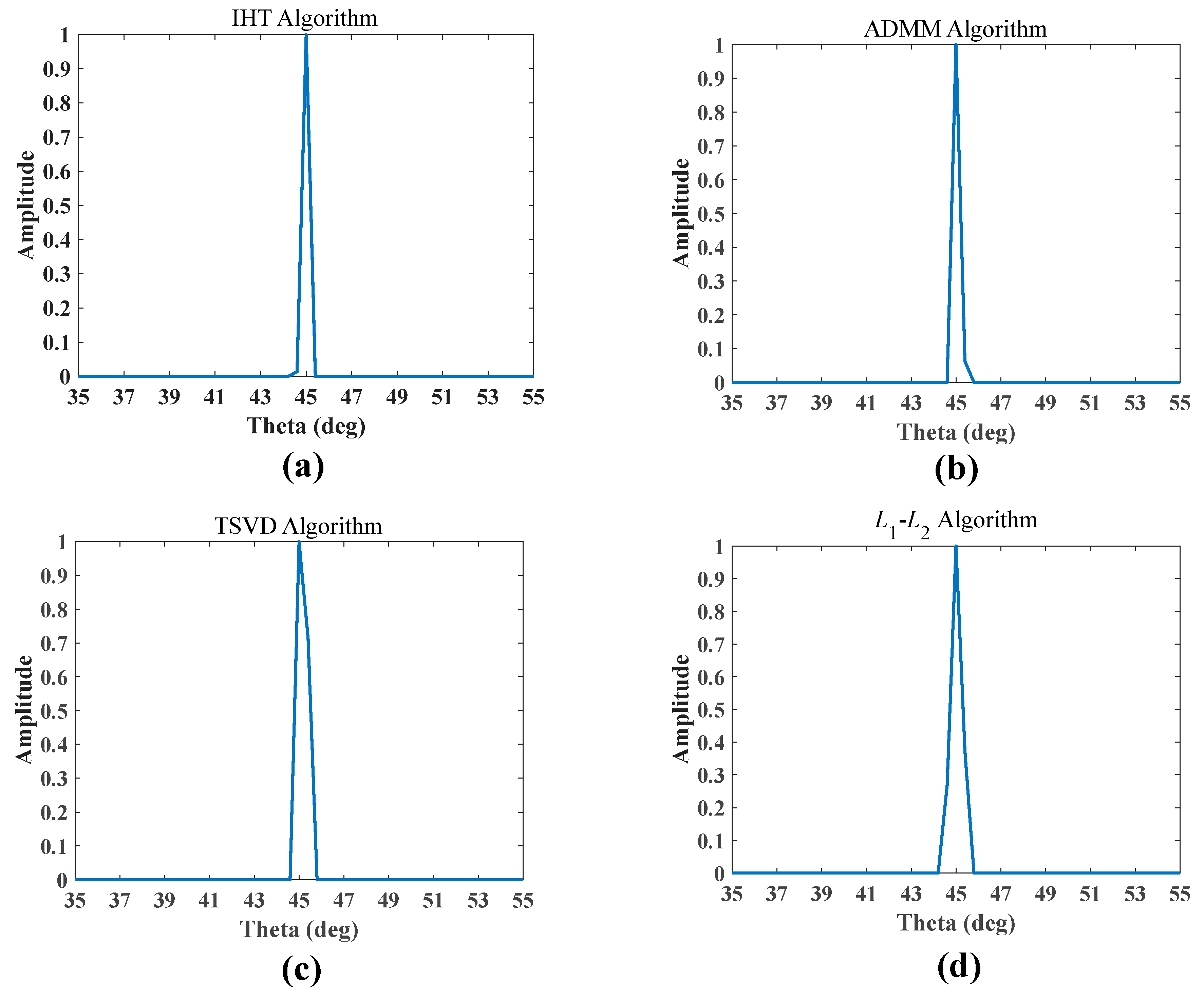
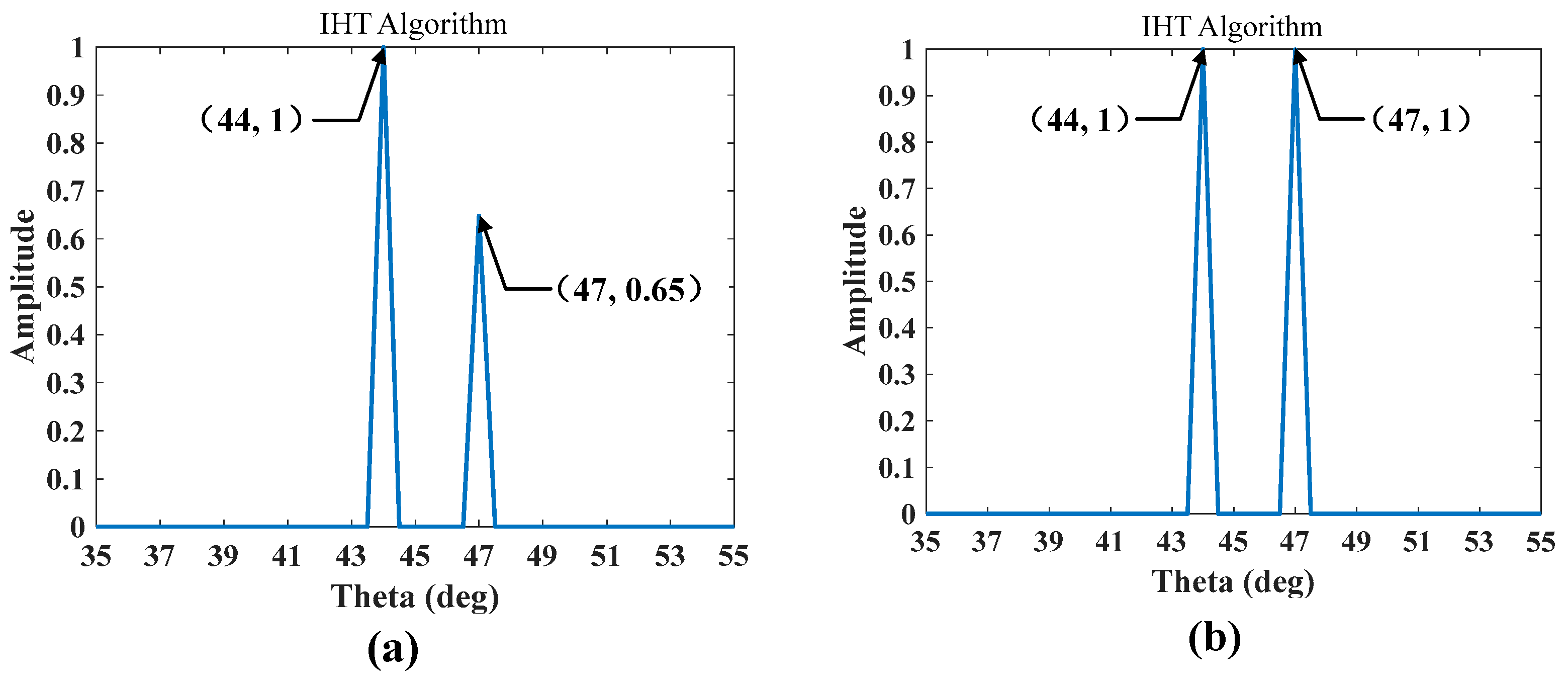
4.1. Simulation Results of Waveform Optimization

To verify that the performance of scanning imaging based on the TMPA antenna is improved using the proposed waveform optimization methods, we first carried out a simulation. The main parameters of the imaging system in this simulation are illustrated in Table 1. The simulated normalized pattern of the TMPA antenna with 32 × 32 elements at 340 GHz is shown in Figure 2a. It can be observed that the TMPA antenna has the ability to steer the THz beam, and when the beam scanning increases from 35° to 55° with step of 5°, the half-power (i.e., 3 dB) beamwidth is slightly increased. The 3 dB beamwidth of the TMPA antenna at the beam scanning angle of 45° is 4.5°, as shown in Figure 2b. Importantly, the beam steering angle of 45° was selected as the center of the azimuth imaging scene because it corresponds to the center of the scanning area.
The original scene contained three point targets, as depicted in Figure 3a. It can be observed that there are two points at (44.6°, 0.448 m) and (45.4°, 0.448 m), and the remaining point is positioned at (45.4°, 0.453 m). Note that the widths of the targets in azimuth are 0.8°, which is significantly less than the 3 dB beamwidth of the TMPA antenna. To demonstrate the performance enhancement of the imaging system through waveform optimization, the range profile under the stepped frequency waveform was initially reconstructed by inverse discrete Fourier transform (IDFT). The simulation results are shown in Figure 3b. Intuitively, the point targets at adjacent distances can be accurately distinguished. However, there are high sidelobes between the peaks. This is due to the fact that the range ambiguity function of the stepped frequency signal exhibits a standard sinc(x) shape, which contributes to the high sidelobe level, as shown in Figure 3c.
In order to suppress the range ambiguity and to reduce the sampling frequency, while ensuring optimal waveform performance under the condition that the number of frequency points in the stepping frequency matched that of the RHF. Only 161 frequency points are randomly extracted from 801 frequency sampling points during the waveform optimization. It should be emphasized that the waveform optimization method employs the Differential Evolution algorithm. The initial frequency set comprises 161 frequency points, the population size is set to 50, and the number of iterations is 200. During each iteration, individual selection is guided by a fitness function aimed at minimizing the sidelobes of the range ambiguity function. The range profile is calculated by IDFT based on zero filling, and the detailed solution process is as follows: First, 161 random sampling frequency points are sorted by location from smallest to largest. Then, the matrix Z is initialized as a zero matrix with a size of 801 × 1. The echo signal at the 161 frequency points is placed in their corresponding positions within matrix Z. Finally, matrix Z is subjected to IDFT. Figure 4a shows the range ambiguity function under the optimized waveform, which is calculated by Equation (7). It is evident that the sidelobe level is suppressed due to the optimization of the random frequency set achieved by the DE algorithm compared with the range ambiguity function under the stepped frequency waveform in Figure 3c. As a result, the range profile performance of the RHF signal is improved compared with the imaging system that utilizes a stepped frequency waveform, as depicted in Figure 4b.
After achieving high-range resolution, the super-resolution in the azimuth was studied. According to Section 3, the optimal waveform in azimuth can be obtained by solving Equation (11), thereby enhancing the imaging performance. Here, in order to better illustrate the enhancement of imaging performance through waveform optimization, different super-resolution imaging algorithms were applied to reconstruct the targets in different azimuths within the range bin before waveform optimization. Figure 5 presents the reconstruction results of the Iterative Hard Thresholding (IHT), Alternating Direction Method of Multipliers (ADMM), Truncated Singular Value Decomposition (TSVD), and hybrid L1L2 regularization algorithms when the target distance is 0.448 m. It is evident that none of these methods are able to distinguish point targets separated by 0.8° in the azimuth direction.
Next, taking the IHT algorithm as an example, the reconstruction results after waveform optimization are presented, as shown in Figure 6. Fortunately, when the optimized waveform is used, the target can be accurately reconstructed, indicating that the proposed waveform design method can effectively improve the resolution in azimuth. And the super-resolution factor, which is equal to 5.625, is obtained by dividing the 3 dB beamwidth of 4.5° by the azimuth resolution angle of 0.8°.
The IHT algorithm was further applied to reconstruct the target with different azimuth at a distance of 0.453 m. As observed in Figure 7a, there was only one point target located at 45.4°. By merging the range and azimuth super-resolution results together, a two-dimensional (2-D) super-resolved image could be obtained, as shown in Figure 7b. It can be observed that the imaging scene is accurately reconstructed, indicating that the super-resolution capability of the imaging system can be enhanced through the combination of random hopping frequency and amplitude modulation for waveform optimization.

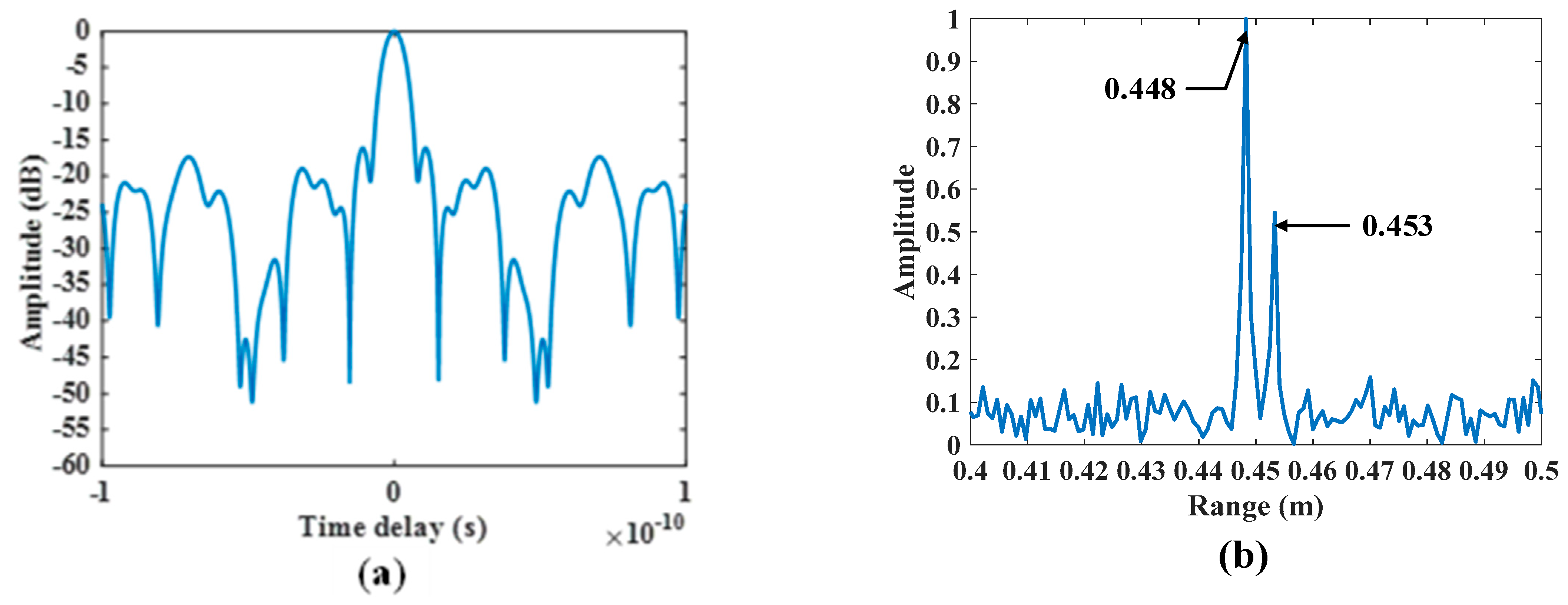
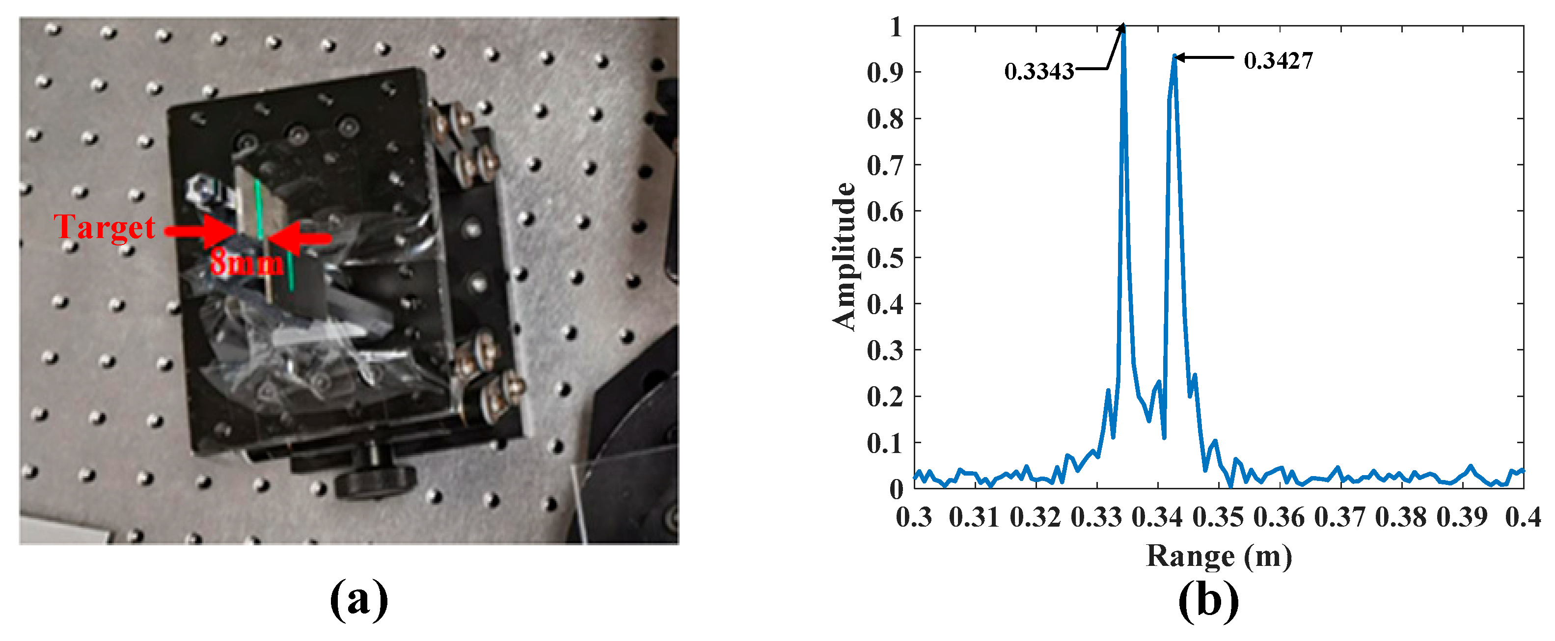
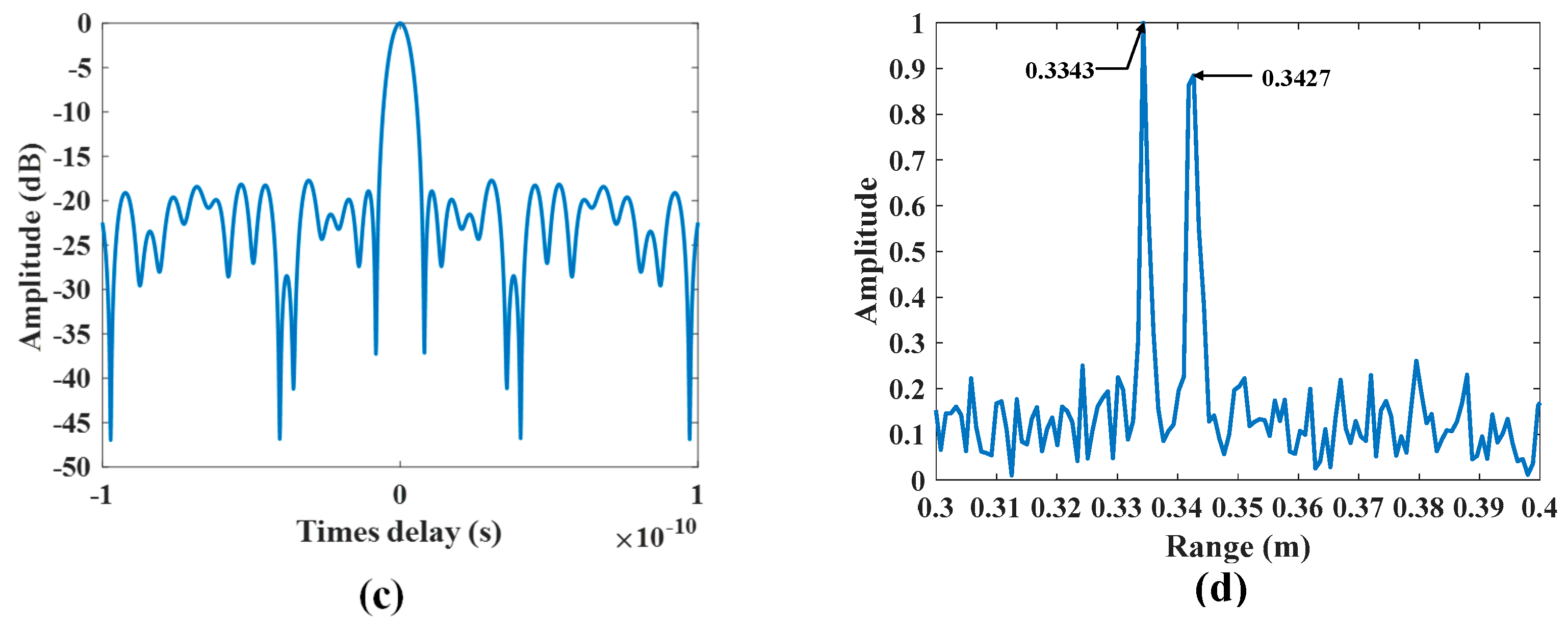
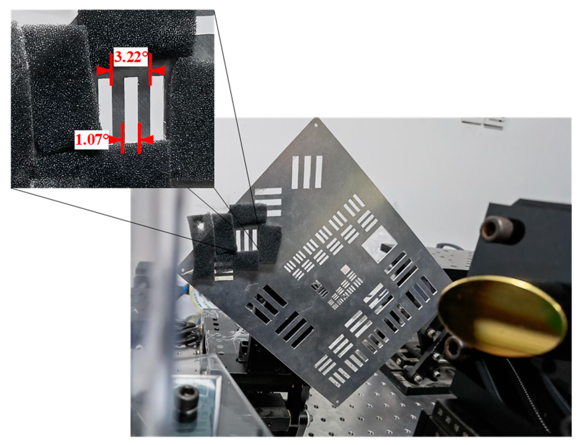
4.2. Experimental Results of Waveform Optimization

In this section, an experiment was conducted to further verify the effectiveness of the proposed waveform optimization method. The experimental THz scanning imaging system is composed of the vector network analyzer, an S-parameter test module, the TMPA antenna designed in [29], an off-axis parabolic mirror, field-programmable gate-array wave-control components, a rotating platform, and an imaging resolution board, as depicted in Figure 8a. The THz wave emitted by the feed source is collimated by the parabolic mirror off-axis to the TMPA antenna, which is controlled by a field-programmable gate array. The incident THz wave is modulated by the TMPA antenna to realize beam scanning of the region of interest on the resolution board, and the reflected waves are collected by a detector. The system parameters of the experiment are basically consistent with that of the simulation, and the measured beam scanning performances at 340.5 GHz are presented in Figure 8b. It can be seen that the 3 dB beamwidth of the measured normalized patterns is larger than that of the simulation normalized patterns, and the 3 dB beamwidth at a scanning angle of 45° is 6.5°. This discrepancy may be attributed to an inaccurate phase resulting from sample processing and imprecise angle measurements due to the rotating platform [23].
Figure 9a presents the target to be resolved in the range direction, which consists of two metal plates separated by a distance of 8 mm. By directly applying IDFT to the echo signals of the target at 801 frequency points arranged in sequence, a one-dimensional range image under a stepped frequency waveform can be obtained, and the result is shown in Figure 9b. It can be seen that the two point targets can be distinguished byh distance and have a relative distance of 8.4 mm. However, there are high sidelobes near the peaks, which may cause the two targets to be indistinguishable when the distance between them is further reduced. Figure 9c shows the range ambiguity function after applying the optimized waveform, whose sidelobe is effectively suppressed. Therefore, a one-dimensional range image with higher performance is obtained, as shown in Figure 9d. The sidelobe of the obtained one-dimensional range image is significantly reduced compared with that from using the stepped frequency waveform. This proves that waveform optimization can achieve higher range resolution and requires fewer sampling frequency points.
Subsequently, experiments were conducted to verify the enhancement in the azimuth super-resolution imaging performance through waveform optimization. Figure 10 presents the target that was imaged, which consists of two vertical metal bars surrounded by absorbing materials. The angular deviations of the inner edge and outer edge of these two metal bars with respect to the center of the TMPA antenna were 1.6° and 4.83°, respectively. Since the azimuth imaging resolution unit of the system was set to 0.5°, the theoretical angle difference of the point target obtained from the inversion was expected to be 2°, 2.5°, 3°, 3.5°, 4°, or 4.5°. The IHT algorithm was utilized to reconstruct the images with and without waveform optimization, and the results are shown in Figure 11. Figure 11a indicates that the target was successfully reconstructed with super-resolution under the stepped-frequency waveform, and the super-resolution multiple was 2.167. However, there was a significant intensity difference at the two angles of 44° and 47°, indicating inaccurate retrieval of the target scattering information. On the other hand, with waveform optimization, not only was azimuth super-resolution of the two metal strips achieved but the target scattering intensity information was accurately reconstructed, as shown in Figure 11b.
To evaluate the super-resolution capability of the imaging system for the target, a more detailed target is presented in Figure 12. The inner edges and outer edges of the two metal strips form angles of 1.07° and 3.22°, respectively, with respect to the center of the TMPA antenna. Consequently, the reconstructed target has an angular difference of 1.5°, 2.0°, 2.5°, or 3.0° in the azimuth. Figure 13a,b present the results of target reconstruction by the IHT algorithm with and without waveform optimization, respectively. Clearly, both of them successfully achieve azimuth-angle resolution of the two metal bars, with a resolution angle of 1.5°. The super-resolution factor is equal to 4.333. However, the difference lies in the fact that the target intensity reconstructed after the waveform optimization is more accurate, indicating a significant enhancement in imaging performance.
Figure 14 presents an additional experimental scenario to further illustrate the enhancement in TMPA scanning radar performance achieved through the proposed waveform optimization algorithm. As shown in Figure 14a, the radar system consists of a central control and signal processing terminal, a TMPA antenna, a THz RF frontend, and a receiving antenna. Three corner reflectors are placed as targets, with one positioned at 7 m and the other two at 7.35 m. These two reflectors are spaced 9 cm apart in the azimuthal direction, as depicted in Figure 14b.
Table 2 presents the radar system parameters based on the TMPA antenna. After performing pulse compression on the radar echoes, super-resolution imaging in the azimuthal direction is conducted for two range cells containing targets. Figure 15a shows the reconstructed result for the first range bin before waveform optimization, where only a single point target is observed. When the IHT algorithm is applied to reconstruct the target in the second range bin, the two point targets cannot be distinguished, as illustrated in Figure 15b. However, through the proposed waveform optimization method, two point targets separated by 9 cm can be accurately reconstructed, as shown in Figure 15c. This further validates the effectiveness of the proposed waveform optimization approach. Figure 15d displays the two-dimensional imaging result after waveform optimization, where it is evident that the imaging result aligns with the target scenario.

5. Conclusions

In this paper, a waveform design method based on RHF and amplitude modulation is proposed for enhancing the performance of a TMPA scanning imaging system. The optimal frequency set within a certain bandwidth is obtained by optimizing the range ambiguity function of the RHF signal through the DE algorithm, thereby achieving a high-resolution range profile. On this basis, the waveform of the TMPA scanning imaging system is further optimized by using amplitude modulation to minimize the residual between the real echo and the reconstructed echo so as to improve the azimuth super-resolution performance. By incorporating RHF and amplitude modulation, the imaging performance of the system can be enhanced effectively, and two-dimensional super-resolution images are obtained. The simulation and experimental results show that compared to the stepped-frequency waveform, the optimized waveform generated by the proposed method effectively suppresses range ambiguity in the range, achieving higher resolution and better imaging quality in the azimuth.

Author Contributions

Conceptualization, H.Z.; methodology, H.Z.; software, H.Z. and C.L. (Chuanying Liang); validation, H.Z.; formal analysis, H.Z.; investigation, H.Z.; resources, H.Z., F.L. and C.L. (Chuanying Liang); data curation, H.Z., F.L. and C.L. (Chuanying Liang); writing—original draft preparation, H.Z.; writing—review and editing, H.Z. and C.L. (Chenggao Luo); visualization, H.Z.; supervision, H.Z. and C.L. (Chenggao Luo); project administration, C.L. (Chenggao Luo) and H.W.; funding acquisition, C.L. (Chenggao Luo) and H.W. All authors have read and agreed to the published version of the manuscript.

Funding

This work was supported by the National Natural Science Foundation of China (under Grant 61971427, Grant 62035014, Grant 61921001, Grant 62201591, and Grant 62322122) and the National Key R&D Program of China (under Grant 2018YFB2202500 and Grant 2022YFB3902400).

Data Availability Statement

The data underlying the results presented in this paper are not publicly available at this time due to privacy restrictions but may be obtained from the authors upon reasonable request.

Acknowledgments

We would like to thank the reviewers for their valuable comments.

Conflicts of Interest

The authors declare no conflicts of interest.

References

  1. Ferguson, B.; Zhang, X.C. Materials for terahertz science and technology. Nat. Mater. 2002, 1, 26–33. [Google Scholar] [CrossRef] [PubMed]
  2. Dong, J.; You, P.; Tomasino, A.; Yurtsever, A.; Morandotti, R. Single-shot ultrafast terahertz photography. Nat. Commun. 2023, 14, 1704. [Google Scholar] [CrossRef] [PubMed]
  3. Fan, L.; Wang, H.; Yang, Q.; Deng, B. High-Quality Airborne Terahertz Video SAR Imaging Based on Echo-Driven Robust Motion Compensation. IEEE Trans. Geosci. Remote Sens. 2024, 62, 2001817. [Google Scholar] [CrossRef]
  4. Siegel, P.H. Terahertz technology. IEEE Trans. Microw. Theory Techn. 2002, 50, 910–928. [Google Scholar] [CrossRef]
  5. Matsumoto, H.; Watanabe, I.; Kasamatsu, A.; Monnai, Y. Integrated terahertz radar based on leaky-wave coherence tomography. Nat. Electron. 2020, 3, 122–129. [Google Scholar] [CrossRef]
  6. Yang, X.; Pi, Y.; Liu, T.; Wang, H. Three-dimensional imaging of space debris with space-based terahertz radar. IEEE Sens. J. 2018, 18, 1063–1072. [Google Scholar] [CrossRef]
  7. Jasteh, D.; Hoare, E.; Cherniakov, M.; Gashinova, M. Experimental Low-Terahertz Radar Image Analysis for Automotive Terrain Sensing. IEEE Geosci. Remote Sens. Lett. 2016, 13, 490–494. [Google Scholar] [CrossRef]
  8. Jamshed, M.A.; Nauman, A.; Abbasi, M.A.B.; Kim, S.W. Antenna selection and designing for THz applications: Suitability and performance evaluation: A survey. IEEE Access 2020, 8, 113246–113261. [Google Scholar] [CrossRef]
  9. Gishkori, S.; Daniel, L.; Gashinova, M.; Mulgrew, B. Imaging for a forward scanning automotive synthetic aperture radar. IEEE Trans. Aerosp. Electron. Syst. 2018, 55, 1420–1434. [Google Scholar] [CrossRef]
  10. Rasheed, I.; Hu, F. Intelligent super-fast vehicle-to-everything 5G communications with predictive switching between mmWave and THz links. Veh. Commun. 2021, 27, 100303. [Google Scholar] [CrossRef]
  11. Li, W.; Niu, M.; Zhang, Y.; Huang, Y.; Yang, J. Forward-looking scanning radar superresolution imaging based on second-order accelerated iterative shrinkage-thresholding algorithm. IEEE J. Sel. Top. Appl. Earth Observ. Remote Sens. 2020, 13, 620–631. [Google Scholar] [CrossRef]
  12. Tuo, X.; Zhang, Y.; Huang, Y.; Yang, J. Fast sparse-TSVD superresolution method of real aperture radar forward-looking imaging. IEEE Trans. Geosci. Remote Sens. 2021, 59, 6609–6620. [Google Scholar] [CrossRef]
  13. Li, W.; Yang, Y.; Huang, J.; Kong, J.; Wu, L. An improved Radon-transform-based scheme of Doppler centroid estimation for bistatic forward-looking SAR. IEEE Geosci. Remote Sens. Lett. 2011, 8, 379–383. [Google Scholar] [CrossRef]
  14. Pu, W.; Li, W.; Wu, J.; Huang, Y.; Yang, J.; Yang, H. An azimuth-variant autofocus scheme of bistatic forward-looking synthetic aperture radar. IEEE Geosci. Remote Sens. Lett. 2017, 14, 689–693. [Google Scholar] [CrossRef]
  15. Pu, W.; Wu, J.; Wang, X.; Huang, Y.; Zha, Y.; Yang, J. Joint sparsity-based imaging and motion error estimation for BFSAR. IEEE Trans. Geosci. Remote Sens. 2019, 57, 1393–1408. [Google Scholar] [CrossRef]
  16. Yuan, Y.; Chen, S.; Zhang, S.; Zhao, H. A chirp scaling algorithm for forward-looking linear-array SAR with constant acceleration. IEEE Geosci. Remote Sens. Lett. 2018, 15, 88–91. [Google Scholar] [CrossRef]
  17. Liu, R.; Ji, C.; Zhao, Z.; Zhou, T. Metamaterials: Reshape and rethink. Engineering 2015, 1, 179–184. [Google Scholar] [CrossRef]
  18. Taghvaee, H.; Cabellos-Aparicio, A.; Georgiou, J.; Abadal, S. Error analysis of programmable metasurfaces for beam steering. IEEE J. Emerg. Sel. Top. Circuits Syst. 2020, 10, 62–74. [Google Scholar] [CrossRef]
  19. Lin, M.; Xu, M.; Wan, X.; Liu, H.; Wu, Z.; Liu, J.; Deng, B.; Guan, D.; Zha, S. Single sensor to estimate DOA with programmable metasurface. IEEE Internet Things J. 2021, 8, 10187–10197. [Google Scholar] [CrossRef]
  20. Tezsezen, E.; Yigci, D.; Ahmadpour, A.; Tasoglu, S. AI-based metamaterial design. ACS Appl. Mater. Interfaces 2024, 16, 29547–29569. [Google Scholar]
  21. Wang, S.R.; Chen, M.Z.; Ke, J.C.; Cheng, Q.; Cui, T.J. Asynchronous Space-Time-Coding Digital Metasurface. Adv. Sci. 2022, 9, 2200106. [Google Scholar] [CrossRef] [PubMed]
  22. Li, L.; Cui, T.J.; Ji, W.; Liu, S.; Ding, J.; Wan, X.; Li, Y.B.; Jiang, M.; Qiu, C.W.; Zhang, S. Electromagnetic reprogrammable coding-metasurface holograms. Nat. Commun. 2017, 8, 197. [Google Scholar] [CrossRef]
  23. Zeng, H.; Lan, F.; Zhang, Y.; Liang, S.; Wang, L.; Yin, J.; Song, T.; Wang, L.; Zhang, T.; Shi, Z.; et al. Broadband terahertz reconfigurable metasurface based on 1-bit asymmetric coding metamaterial. Opt. Commun. 2020, 458, 124770. [Google Scholar] [CrossRef]
  24. Xu, J.S.; Liu, W.W.; Song, Z.Y. Terahertz dynamic beam steering based on graphene coding metasurfaces. IEEE Photon. J. 2021, 13, 4600409. [Google Scholar] [CrossRef]
  25. Lynch, J.J.; Herrault, F.; Kona, K.; Virbila, G.; McGuire, C.; Wetzel, M.; Fung, H.; Prophet, E. Coded aperture subreflector array for high resolution radar imaging. Proc. SPIE 2019, 1099405, 18. [Google Scholar]
  26. Venkatesh, S.; Lu, X.; Saeidi, H.; Sengupta, K. A high-speed programmable and scalable terahertz holographic metasurface based on tiled CMOS chips. Nat. Electron. 2020, 3, 785–793. [Google Scholar] [CrossRef]
  27. Jalili, H.; Momeni, O. A 436-to-467 GHz Lens-Integrated Reconfigurable Radiating Source with Continuous 2D Steering and Multi-Beam Operations in 65nm CMOS. In Proceedings of the 2021 IEEE International Solid-State Circuits Conference (ISSCC), San Francisco, CA, USA, 13–22 February 2021; Volume 64, pp. 326–328. [Google Scholar]
  28. Monroe, N.M.; Dogiamis, G.C.; Stingel, R.; Myers, P.; Chen, X.; Han, R. Electronic THz Pencil Beam Forming and 2D Steering for High Angular-Resolution Operation: A 98×98-Unit 265GHz CMOS Reflectarray with In-Unit Digital Beam Shaping and Squint Correction. In Proceedings of the 2022 IEEE International Solid-State Circuits Conference (ISSCC), San Francisco, CA, USA, 20–26 February 2022; Volume 65, pp. 1–3. [Google Scholar]
  29. Lan, F.; Wang, L.; Zeng, H.; Liang, S.; Song, T.; Liu, W.; Mazumder, P.; Yang, Z.; Zhang, Y.; Mittleman, D.M. Real-time programmable metasurface for terahertz multifunctional wave front engineering. Light Sci. Appl. 2023, 12, 191. [Google Scholar] [CrossRef]
  30. Migliaccio, M.; Gambardella, A. Microwave radiometer spatial resolution enhancement. IEEE Trans. Geosci. Remote Sens. 2005, 43, 1159–1169. [Google Scholar] [CrossRef]
  31. Zhang, Y.; Zhang, Y.; Li, W.; Huang, Y.; Yang, J. Super-resolution surface mapping for scanning radar: Inverse filtering based on the fast iterative adaptive approach. IEEE Trans. Geosci. Remote Sens. 2018, 56, 127–144. [Google Scholar] [CrossRef]
  32. Huo, W.; Tuo, X.; Zhang, Y.; Zhang, Y.; Huang, Y. Balanced Tikhonov and total variation deconvolution approach for radar forward-looking super-resolution imaging. IEEE Geosci. Remote Sens. Lett. 2021, 19, 3505805. [Google Scholar] [CrossRef]
  33. Yang, H.; Yang, F.; Xu, S.; Li, M.; Cao, X.; Gao, J.; Zheng, Y. A study of phase quantization effects for reconfigurable reflectarray antennas. IEEE Antennas Wirel. Propag. Lett. 2017, 16, 302–305. [Google Scholar] [CrossRef]
  34. Nayeri, P.; Yang, F.; Elsherbeni, A.Z. Reflectarray Antennas: Theory, Designs, and Applications; Wiley: Hoboken, NJ, USA, 2018. [Google Scholar]
  35. Huang, T.; Liu, Y.; Meng, H.; Wang, X. Cognitive random stepped frequency radar with sparse recovery. IEEE Trans. Aerosp. Electron. Syst. 2014, 50, 858–870. [Google Scholar] [CrossRef]
  36. Dai, F.; Zhang, S.; Li, L.; Liu, H. Enhancement of metasurface aperture microwave imaging via information-theoretic waveform optimization. IEEE Trans. Geosci. Remote Sens. 2022, 60, 5109512. [Google Scholar] [CrossRef]
  37. Qin, A.K.; Huang, V.L.; Suganthan, P.N. Differential evolution algorithm with strategy adaptation for global numerical optimization. IEEE Trans. Evol. Comput. 2009, 13, 398–417. [Google Scholar] [CrossRef]
  38. Sarker, R.A.; Elsayed, S.M.; Ray, T. Differential evolution with dynamic parameters selection for optimization problems. IEEE Trans. Evol. Comput. 2014, 18, 689–707. [Google Scholar] [CrossRef]
Figure 1. Schematic of the scanning imaging model based on the TMPA antenna.
Remotesensing 17 01595 g001
Figure 2. The simulated normalized antenna pattern at 340 GHz for (a) different scanning directions and (b) a 45° scanning angle.
Remotesensing 17 01595 g002
Figure 3. (a) The original scene. (b) The range profile results and (c) range ambiguity function of the imaging system with the stepped frequency waveform.
Remotesensing 17 01595 g003
Figure 4. (a) The range ambiguity function and (b) range profile results of the imaging system with an RHF waveform.
Remotesensing 17 01595 g004
Figure 5. The target reconstruction results of different algorithms. (a) IHT algorithm. (b) ADMM algorithm. (c) TSVD algorithm. (d) L1L2 algorithm.
Remotesensing 17 01595 g005
Figure 6. Results of the super-resolution method with waveform optimization.
Remotesensing 17 01595 g006
Figure 7. Imaging results with waveform optimization. (a) Reconstruction of azimuth within the range unit containing 0.453 m. (b) 2-D image formed from the angle and range data.
Remotesensing 17 01595 g007
Figure 8. (a) Photograph of the experimental TMPA antenna-based imaging system. (b) The measured normalized patterns at 340.5 GHz.
Remotesensing 17 01595 g008
Figure 9. (a) The target to be resolved in range. (b) The experimental range profile results with the stepped frequency waveform. (c) The range ambiguity function and (d) range profile results of the imaging system with an RHF waveform.
Remotesensing 17 01595 g009aRemotesensing 17 01595 g009b
Figure 10. The resolution board with widely spaced metal strips for imaging.
Remotesensing 17 01595 g010
Figure 11. The experimental results of azimuth super-resolution in the scanning imaging system (a) without and (b) with waveform optimization.
Remotesensing 17 01595 g011
Figure 12. The resolution board with narrowly spaced metal bars for imaging.
Remotesensing 17 01595 g012
Figure 13. The experimental results of azimuth super-resolution in the scanning imaging system (a) without and (b) with waveform optimization.
Remotesensing 17 01595 g013
Figure 14. Experimental setup. (a) Radar systems. (b) Target scenario.
Remotesensing 17 01595 g014
Figure 15. (a) Imaging result of the first range cell before waveform optimization. (b) Imaging result of the second range cell before waveform optimization. (c) Imaging result of the second range cell after waveform optimization. (d) Two-dimensional imaging result after waveform optimization.
Remotesensing 17 01595 g015
Table 1. Simulated parameters.
ParametersValue
Element number32 × 32
Scanning area35~55°
Scanning step0.5°
Center frequency330 GHz
Bandwidth140 GHz
Frequency interval0.175 GHz
Amplitude modulation range0.4~2
Table 2. Radar system parameters.
ParametersValue
Element number48 × 48
Scanning area−5~2°
Scanning step0.2°
Center frequency216 GHz
Bandwidth900 MHz
Signal timewidth20 μs
Disclaimer/Publisher’s Note: The statements, opinions and data contained in all publications are solely those of the individual author(s) and contributor(s) and not of MDPI and/or the editor(s). MDPI and/or the editor(s) disclaim responsibility for any injury to people or property resulting from any ideas, methods, instructions or products referred to in the content.

