Technical Note

Bayesian Time-Domain Ringing Suppression Approach in Impulse Ultrawideband Synthetic Aperture Radar

1
National Key Laboratory of Microwave Imaging, Aerospace Information Research Institute, Chinese Academy of Sciences, Beijing 100190, China
2
School of Electronic, Electrical and Communication Engineering, University of Chinese Academy of Sciences, Beijing 100049, China
3
The 27th Research Institute of China Electronics Technology Group Corporation, Zhengzhou 450047, China
*
Author to whom correspondence should be addressed.
Remote Sens. 2025, 17(8), 1455; https://doi.org/10.3390/rs17081455
Submission received: 13 February 2025 / Revised: 10 April 2025 / Accepted: 17 April 2025 / Published: 18 April 2025

Abstract

Impulse ultrawideband (UWB) synthetic aperture radar (SAR) combines high-azimuth-range resolution with robust penetration capabilities, making it ideal for applications such as through-wall detection and subsurface imaging. In such systems, the performance of UWB antennas is critical for transmitting high-power, large-bandwidth impulse signals. However, two primary factors degrade radar imaging quality: (1) inherent limitations in antenna radiation efficiency, which lead to low-frequency signal loss and subsequent time-domain ringing artifacts; (2) impedance mismatch at the antenna terminals, causing standing wave reflections that exacerbate the ringing phenomenon. This study systematically analyzes the mechanisms of ringing generation, including its physical origins and mathematical modeling in SAR systems. Building on this analysis, we propose a Bayesian ringing suppression algorithm based on sparse optimization. The method effectively enhances imaging quality while balancing the trade-off between ringing suppression and image fidelity. Validation through numerical simulations and experimental measurements demonstrates significant suppression of time-domain ringing and improved target clarity. The proposed approach holds critical importance for advancing impulse UWB SAR systems, particularly in scenarios requiring high-resolution imaging.

1. Introduction

Impulse radar, with its advantages of simple system structure, minimal signal attenuation, and small detection blind spots [1,2,3,4], is widely deployed in urban warfare, counter-terrorism, and post-disaster rescue scenarios [5,6,7]. As a representative ultrawideband (UWB) radar system, it emits impulse signals characterized by large instantaneous bandwidth, enabling extremely high range resolution. To achieve superior imaging capabilities, nanosecond or even picosecond pulses are typically utilized. However, the wide bandwidth of impulse signals imposes stringent requirements on the radar hardware, particularly the antenna’s UWB response performance. Any mismatch or distortion in the antenna’s frequency/phase characteristics may lead to waveform distortion of the transmitted/received pulses, resulting in time-domain ringing (TDR) artifacts [8,9,10]. These artifacts manifest as spurious echoes in synthetic aperture radar (SAR) images, significantly degrading target detectability and image interpretability.
Efforts to suppress TDR through hardware-based approaches have been extensively explored. A common strategy involves impedance matching techniques, such as resistive loading or balun optimization, to minimize multiple reflections within the antenna structure [10,11]. Additionally, absorbing materials with tailored electromagnetic properties are integrated into antenna designs to attenuate residual oscillations [12]. Another direction focuses on antenna miniaturization and geometry optimization (e.g., elliptical dipoles or tapered slot antennas) to enhance transient response characteristics [13,14]; while these methods demonstrate partial success in mitigating TDR, they inherently introduce energy dissipation, leading to at least 3 dB reduction in antenna gain [8]. This trade-off between ringing suppression and signal-to-noise ratio (SNR) degradation fundamentally limits the effectiveness of hardware-centric solutions, particularly in low-power or long-range scenarios. Furthermore, hardware modifications often lack adaptability to dynamic operational environments, necessitating a paradigm shift toward signal processing-based suppression techniques.
Existing signal processing methods for TDR suppression, such as the impulse signal ringing mechanism model proposed for through-wall radar [15], often oversimplify the problem by neglecting the frequency-dependent antenna loss effects. This simplification restricts their applicability to real-aperture systems and fails to address the complex ringing patterns in SAR imaging. In this paper, we present a comprehensive analysis of TDR generation mechanisms, emphasizing two critical factors: (1) multiple reflections within the antenna–transceiver chain; (2) low-frequency losses inherent to UWB antenna designs. Building on this analysis, we propose a novel SAR signal ringing model that formulates the suppression task as a deconvolution problem. Unlike traditional spectral estimation approaches [5,16,17,18,19,20,21], which suffer from resolution–ambiguity trade-offs, our algorithm leverages sparse optimization to achieve efficient TDR suppression with minimal impact on image entropy. Specifically, TDR manifests as the generation of accompanying peaks following the main lobe. These artifacts resemble sidelobes but exhibit significantly stronger intensity while maintaining the half-power width of the main lobe unchanged, thereby preserving resolution. Traditional super-resolution methods have generally focused on improving resolution under constraints of limited radar aperture or bandwidth. However, in impulse radar systems where the range resolution is already sufficiently high, the model developed in this paper is solely intended for suppressing TDR without altering the inherent resolution characteristics. Experimental validation using both simulated and measured data demonstrates significant improvement in SAR image quality.
Traditional spectral estimation algorithms such as least squares estimation (LSE) [16] offers simplicity in implementation but suffers from limited resolution due to its inherent bias–variance trade-off, especially under low-SNR conditions. minimum variance distortionless response (MVDR) [17,18] improves resolution by adaptively minimizing interference power; yet, its performance critically depends on accurate covariance matrix estimation, making it sensitive to model mismatches and small-sample effects. More advanced methods like the iterative adaptive approach (IAA) [19,20] achieve super-resolution capabilities through nonparametric iterative weighting, but is also sensitive to model mismatches; while these methods partially address ringing artifacts, they share a common limitation: they treat spectral estimation as a deterministic optimization problem, neglecting the statistical nature of noise and prior knowledge of signal sparsity. This leads to suboptimal performance in scenarios with strong clutter or non-stationary interference, where precise separation of ringing components becomes challenging.
To overcome these limitations, we adopt a Bayesian framework that inherently incorporates sparsity priors and uncertainty quantification. Unlike LSE or MVDR, which rely on deterministic regularization, the Bayesian approach models the ringing components and target responses as probabilistic distributions, enabling joint estimation of parameters and hyperparameters through hierarchical inference [21]. This not only suppresses TDR more robustly but also preserves weak target signatures often obscured by traditional methods.
While our work focuses on impulse signal ringing in UWB SAR systems, the physical origins of such artifacts share fundamental parallels with oscillatory phenomena observed across signal processing and imaging domains. These oscillations universally arise from abrupt signal discontinuities interacting with system constraints. In the case of impulse ringing, steep temporal edges (e.g., sharp transitions in ultrawideband pulses) induce energy leakage when filtered through bandlimited systems, generating oscillations through spectral truncation. This mechanism mirrors the Gibbs phenomenon in Fourier-based reconstructions [22], where abrupt spectral truncation of step-like signals produces oscillatory ripples near edges. Similarly, edge ghosting in compressive sensing MRI [23,24] emerges from sparse representation mismatches during signal sampling, causing spurious oscillations at abrupt spatial boundaries. Despite differing physical contexts, all these artifacts stem from a common root: mismatched representations between signal discontinuities and system basis functions. The oscillations manifest as energy redistribution from abrupt transitions to neighboring regions, whether in SAR imagery, Fourier-reconstructed edges, or MRI scans. This universality underscores the importance of adaptive basis functions or regularization techniques to mitigate such artifacts across disciplines.
The remainder of this paper is organized as follows: Section 2 rigorously analyzes the physical mechanisms of ringing generation and establishes the SAR signal model. Section 3 details the proposed Bayesian ringing suppression algorithm. Section 4 validates the method through comparative experiments, and Section 5 concludes with potential applications beyond SAR systems.

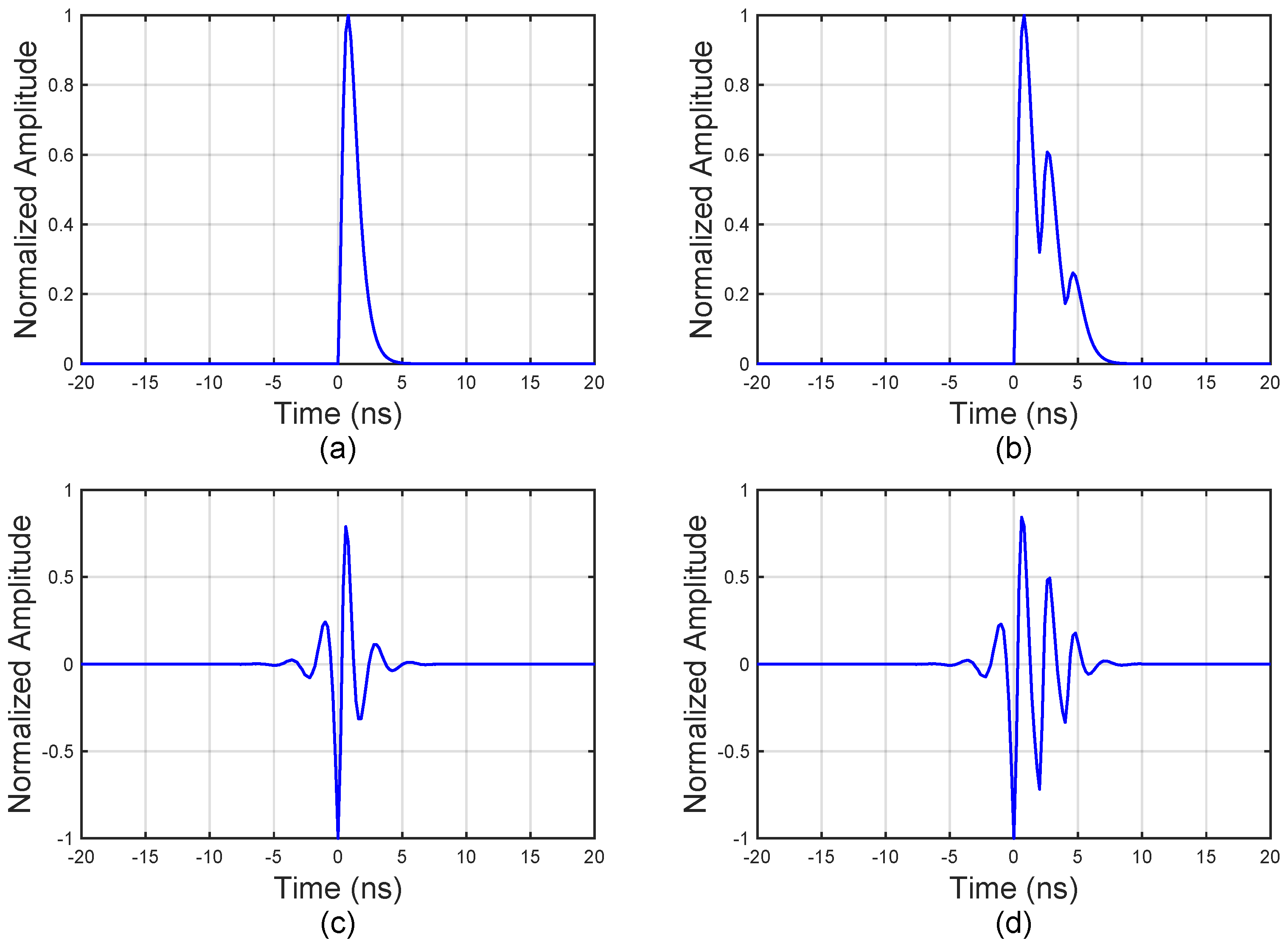
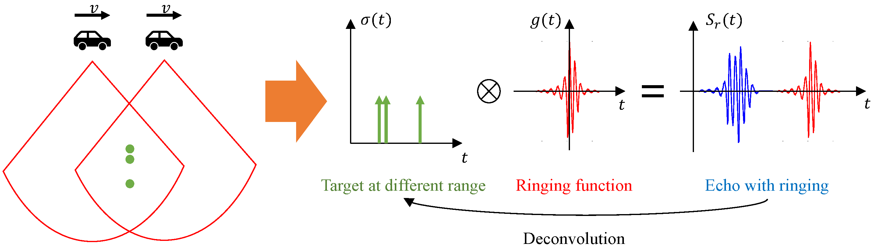
2. Signal Ringing Model

The power source of the impulse signal in this study comprises a solid-state pulse generator that produces a double-exponential waveform. As depicted in Figure 1a, pulse generators utilized in transient radar systems typically generate a voltage envelope characterized by a rapid rise time followed by a gradual decay. This waveform can be mathematically represented by the following analytical expression [25]:
s ( t ) = 4 exp t T r 1 + t T r exp t T d u ( t )
where u ( t ) denotes the Heaviside step function, and T r and T d are time constants proportional to the rise time and decay time of the pulse generator waveform, respectively, with T r < T d .
According to transmission line theory, impedance discontinuities cause the signal to undergo multiple reflections between the terminals and the feed point [26]. These reflections result in signal ringing. Additionally, the high-pass characteristics of the antenna often impede the radiation of low-frequency signals, exacerbating the TDR effects.
The frequency-domain representation of the impulse signal affected by TDR can be expressed as:
S ring ( j ω ) = S ( j ω ) H 1 ( j ω ) H 2 ( j ω )
where S ( j ω ) is the spectrum of s ( t ) , H 1 ( j ω ) represents the frequency response of the antenna, and H 2 ( j ω ) denotes the frequency response due to multiple signal reflections. The antenna’s frequency response H 1 ( j ω ) can be modeled as a band-pass filter to account for its limited bandwidth and high-pass nature. Specifically, a Butterworth or Chebyshev band-pass filter is often employed to approximate the antenna’s frequency response [27,28], as these filters provide a sharp transition band and flat passband characteristics, which are suitable for simulating the antenna’s behavior.
The antenna’s band-pass characteristics can be mathematically represented using a third-order Butterworth filter model:
H 1 ( j ω ) = 1 1 + ω ω c 2 n
where ω c denotes the cutoff frequency and n determines the roll-off steepness. For UWB antennas operating in f c 1 f c 2 (typically 0.4−2.4 GHz), the cutoff frequencies are set as ω c 1 = 2 π f c 1 and ω c 2 = 2 π f c 2 . The phase response ϕ ( ω ) is modeled as:
ϕ ( ω ) = τ g ω + β 2 ω 2
where τ g represents group delay and β quantifies phase dispersion. This dual-pole band-pass model accurately captures the antenna’s frequency-dependent distortion effects on transmitted pulses.
The frequency response of multiple signal reflections H 2 ( j ω ) is given by [15]:
H 2 ( j ω ) = 2 π δ ( ω ) + i = 1 K ρ i s ( t ( 2 i ) t d )
where K is the number of reflections, ρ i is the reflection coefficient influenced by the antenna impedance, and t d is the time delay between the terminal and the feed point. Figure 1 illustrates the original impulse signal and the signals affected by multiple reflections and low-frequency losses. As shown in Figure 1, the ringing phenomenon is primarily influenced by impedance discontinuities and bandwidth limitations.
The echo data received by the impulse synthetic aperture radar (SAR) can be described as the delayed version of the impulse signal with ringing, observed from different azimuth directions. The received signal is expressed as follows:
s r ( τ , η ) = i = 1 L s ring ( τ t i , η ) , t i = 2 R i c
where L is the number of scattering centers, R i is the distance between the ith scattering center and the radar, t i is the delay associated with the ith scattering center, and c is the speed of light in air.
The quadrature component of the received signal is obtained using the Hilbert transform, resulting in a complex signal:
s re ( τ , η ) = s r ( τ , η ) + Hilbert [ s r ( τ , η ) ]
Given the large instantaneous bandwidth of impulse signals, estimating the Doppler frequency is challenging [29,30]. Consequently, time-domain imaging algorithms, such as the back-projection (BP) algorithm, are typically employed for two-dimensional imaging:
I ( m , n ) = k = 1 N a s re , k ( T m , n , k , η )
where s re , k represents the radar echo signal at the kth azimuth point, N a is the number of azimuth samples, and T m , n , k is the round-trip delay between the azimuth location and the imaging point ( m , n ) . I ( m , n ) denotes the two-dimensional SAR imaging result incorporating TDR effects.

3. Ringing Suppression Algorithm

For a determined impulse SAR system, two problems arise when attempting to suppress TDR. First, the form of TDR differs moderately for targets in different azimuths due to the antenna’s response. Second, the data size of SAR echo signal is large, requiring more storage and computational resources. Furthermore, the form of TDR varies significantly with different type of UWB antennas. Considering these issues, this paper presents an efficient ringing suppression algorithm based on SAR images.
Under the condition that the ringing pattern remains consistent within a specific azimuth, the point spread function (PSF) of a target that has undergone complete synthetic aperture processing is also consistent. Thus, we can consider the SAR image as being composed of multiple PSFs with TDR. As shown in Figure 2, the imaging result is obtained by convolving the point targets at different positions with the ringing signal of a standard point target. The ringing suppression problem is then transformed into a deconvolution issue.
Assume S is the received signal vector, representing the 2D image I at a certain azimuth position across different ranges. Let M be the number of range points in the image, and the received signal is given by:
S = s 1 , s 2 , , s M T
Let σ represent a scattering coefficient vector of length N, where N is the number of unknown scattering coefficients within the imaging area:
σ = σ 1 , σ 2 , , σ N T
where G represents the sampled time-domain response of a standard impulse, and L is the sampling length, which is then zero-padded to length M:
g = g 1 , g 2 , , g L , 0 , , 0 T
The matrix Φ is an M × N matrix given by:
Φ = e j 2 π ( M 2 + 1 ) 1 N e j 2 π ( M 2 + 1 ) 2 N e j 2 π ( M 2 + 1 ) N N e j 2 π ( M 2 + 2 ) 1 N e j 2 π ( M 2 + 2 ) 2 N e j 2 π ( M 2 ) 1 N e j 2 π ( M 2 ) N N
This matrix performs an element-wise multiplication ⊙ with the frequency spectrum of the standard impulse response to form the measurement matrix of the model.
Then, the ringing convolution model for each azimuth signal can be written in matrix–vector form, as follows:
S = G Φ σ + n
where S = F F T ( s ) and G = F F T ( g ) represent the frequency spectrum of the signal vector and the standard impulse response, respectively. The columns of measurement matrix represent the steering vectors of the unknown scattering points at different locations.
Considering the imaging characteristic, the Laplace distribution is employed to model the sparsity property imaging scene. Based on this assumption, the likelihood probability function can be given as:
PDF ( σ i γ ) = γ 2 exp γ σ i 1
where γ is the scale parameter. Under the independent and identically distributed (i.i.d.) assumption, the joint pdf of σ can be expressed as:
PDF ( σ γ ) = γ 2 N exp γ i = 1 N σ i 1 = γ 2 N exp γ σ 1
Typically, the complex Gaussian distribution is used to describe noise, and the noise satisfies n N ( 0 , ϵ 2 ) . The pdf of the noise can be written as:
PDF ( n ϵ 2 ) = 1 ( 2 π ϵ 2 ) N / 2 exp 1 2 ϵ 2 n 2 2
where · 2 is the l 2 -norm. The likelihood function is then:
PDF ( S σ , ϵ 2 ) = 1 ( 2 π ϵ 2 ) N / 2 exp 1 2 ϵ 2 S G Φ σ 2 2
Given the Laplace-distributed sparse scene prior (15) and the Gaussian noise model (17), the maximum a posteriori (MAP) estimate is derived from Bayes’ theorem:
PDF ( σ S , γ , ϵ 2 ) PDF ( S σ , ϵ 2 ) · PDF ( σ γ )
where the posterior distribution is proportional to the product of the likelihood (17) and the prior (15). The normalization constant (evidence term) is omitted because it does not affect the maximization over σ .
The MAP estimate seeks the sparse reflectivity vector σ that maximizes this posterior probability. Substituting (15) and (17) into Bayes’ rule yields:
σ ^ = arg max σ PDF ( S σ , ϵ 2 ) · PDF ( σ γ )
After applying the logarithmic transformation, we obtain:
σ ^ = arg max σ log 10 PDF ( S σ , ϵ 2 ) + log 10 PDF ( σ γ )
To simplify the expression, (20) can be rewritten as:
σ ^ = arg max σ 1 2 ϵ 2 S G Φ σ 2 2 γ σ 1
σ ^ = arg min { S G Φ σ 2 2 + μ σ 1 } = arg min J ( σ )
where J ( σ ) = S G Φ σ 2 2 + μ σ 1 . μ = 2 ϵ 2 γ is the regularization coefficient, which serves as a critical balancing parameter derived from the product of: (1) the noise variance ϵ 2 (characterizing measurement uncertainty in (16), and (2) the Laplace prior parameter γ (governing scene sparsity in (14). This dual dependence enables μ to automatically adapt to both the observed noise level and the intrinsic scene complexity.
The coefficient’s operational impact manifests through two asymptotic regimes: when μ 0 , solutions prioritize data matching at the risk of noise amplification; whereas μ enforces extreme sparsity that may suppress weak scatterers. Practical implementations therefore require careful selection of μ to navigate between these extremes—a process guided by the Bayesian MAP framework (18) and operational considerations detailed in [20,31,32,33].

4. Experiments

The performance of the proposed Bayesian method is validated through numerical simulations and real scene experiments; then, it is compared with the results of other traditional methods, including least square estimation (LSE), minimum variance distortionless response (MVDR), and iterative adaptive approach (IAA). All the methods are implemented in MATLAB (R2022b) code and executed on a computer with a CPU at 2.5 GHz and 16 GB RAM.

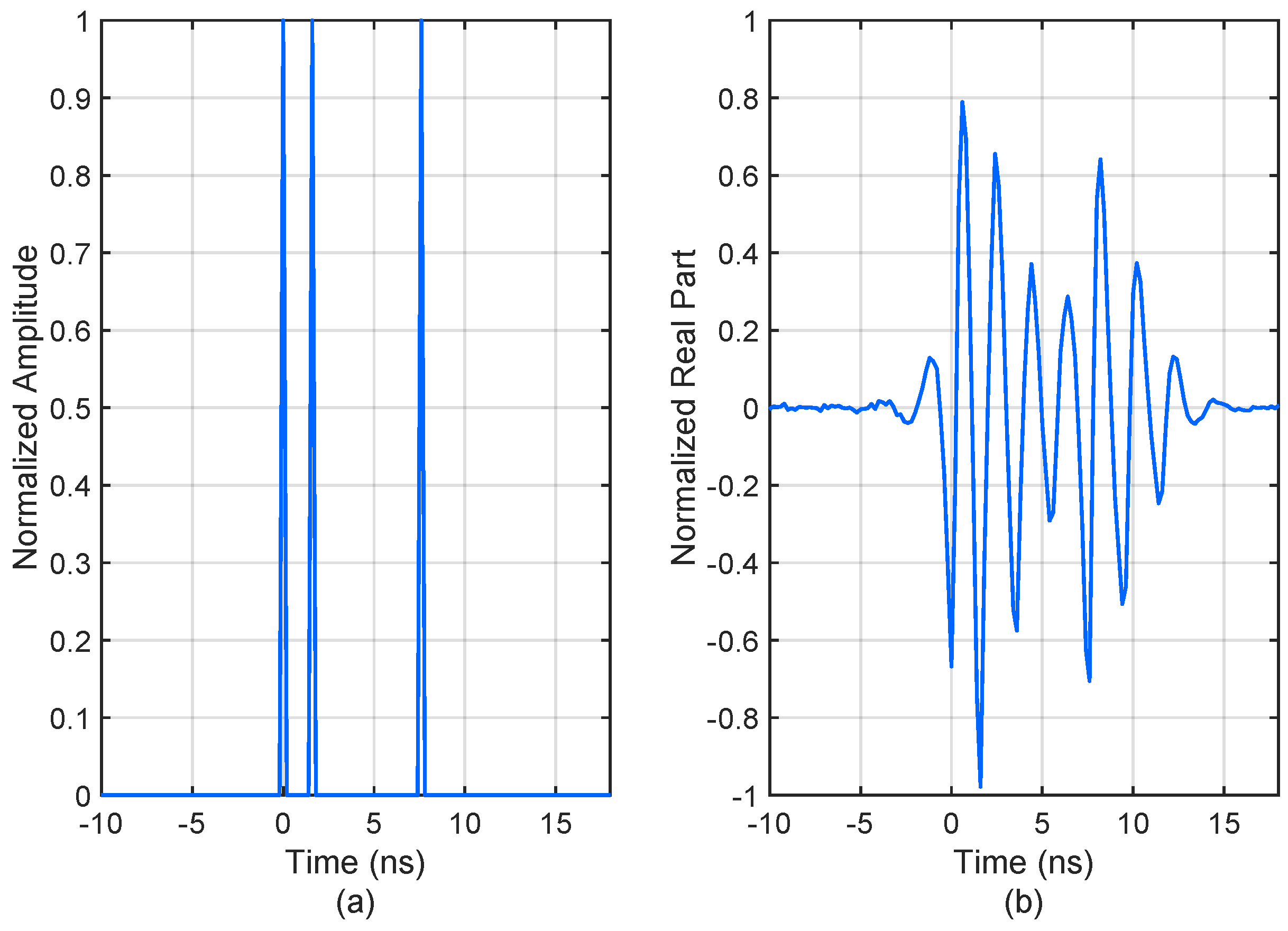
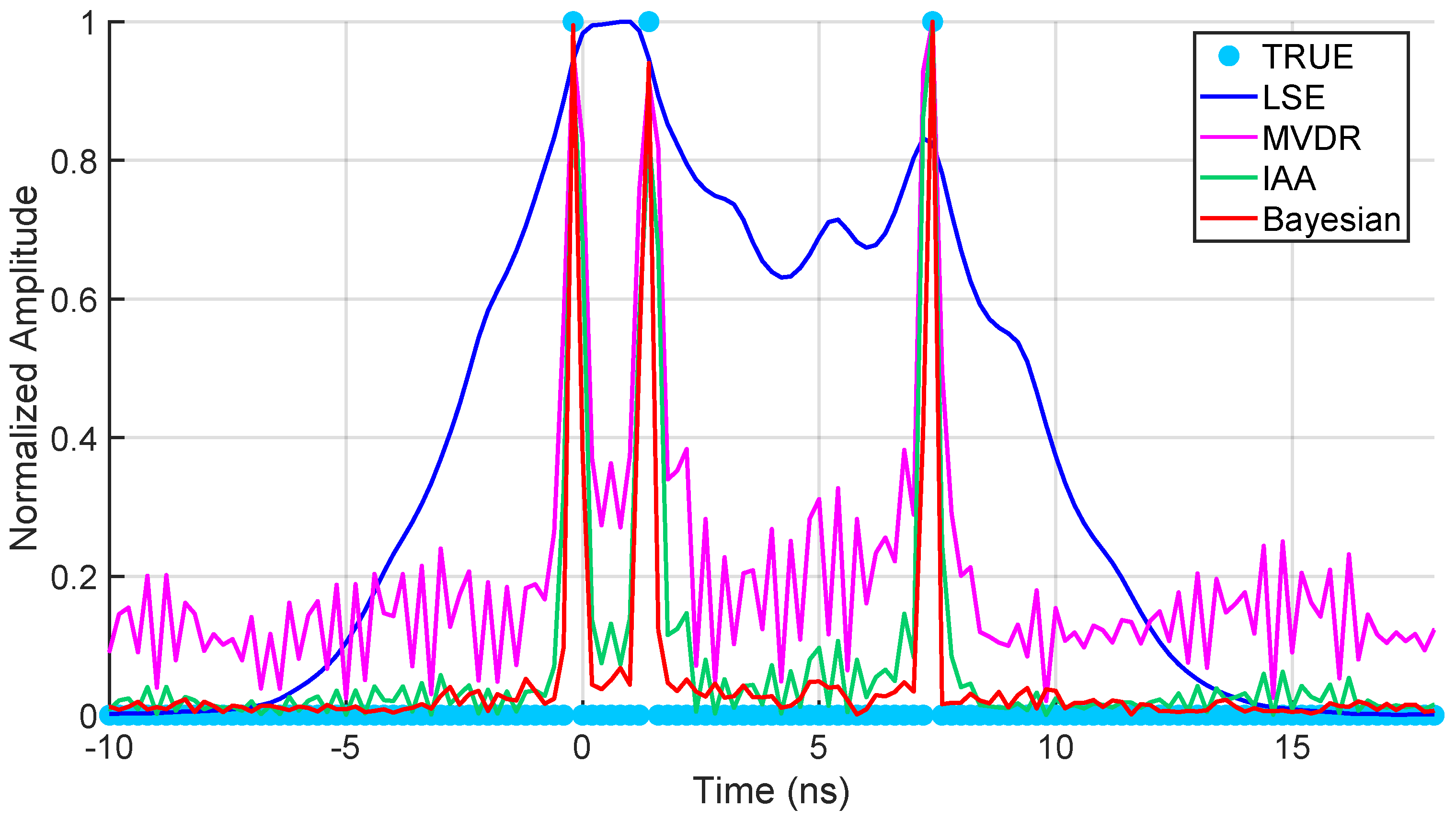
4.1. Point Targets Simulation

As shown in Figure 3a, three point targets are considered in the simulation, which are located at 0 ns, 1.5 ns, and 7.5 ns. Their amplitudes are with the same value. The simulation parameters of the signal with TDR are shown in Table 1. Figure 3b gives the received signal, from which it is difficult to recognize the three point targets because of TDR.
In this simulation, the white Gaussian noise with SNR of 30 dB is added to the signal. After ringing suppression by LSE, MVDR, IAA, and Bayesian, the results are given in Figure 4.
From Figure 4, we can see that the two closely spaced point targets are hard to be recovered for LSE method, while the MVDR and IAA method can distinguish the targets and the outline of the targets is sharpened. However, the MVDR and IAA methods suffer from severe transverse ripples and sidelobes. Obviously, the proposed Bayesian method has the best performance among all the ringing suppression methods.

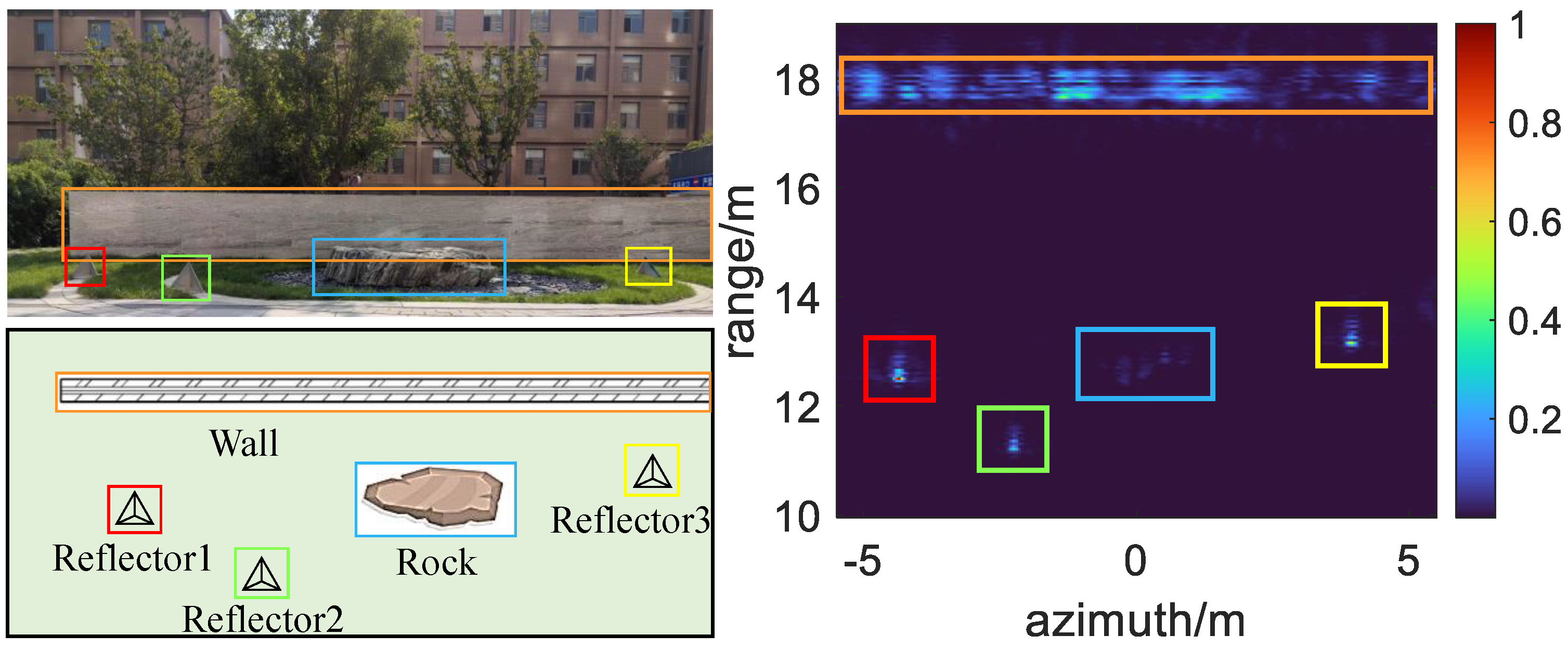
4.2. Real Scene Experiments

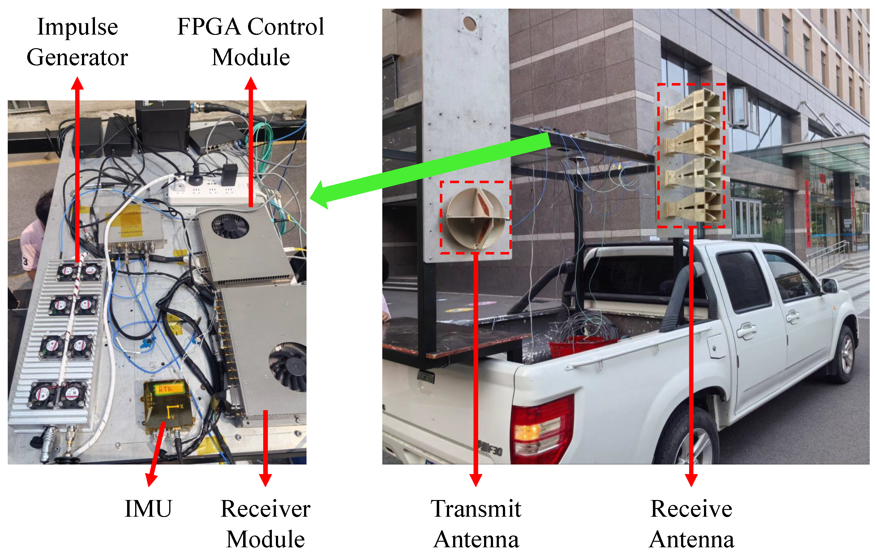
4.2.1. Experimental Setup and Radar System Introduction

In this section, to further verify the performance and robustness of the proposed method under practical conditions, experimental validation was conducted using data collected from real-world scenarios. As illustrated in Figure 5, the experimental setup was designed to simulate a complex environment with multiple reflective surfaces and obstacles. Three high-precision corner reflectors were strategically positioned on both sides of a large rock formation, which served as a natural obstruction. Behind the rock and corner reflectors, a brick wall with dimensions of approximately 2 m in height and 10 m in length was chosen to represent a typical obstacle encountered in real-world applications, thereby increasing the complexity of the scene.
The SAR system utilized in this study is depicted in Figure 6, showcasing the integration of advanced electronic modules and a robust vehicle platform designed for high-precision radar imaging. At the core of the system is the impulse generator, which produces UWB impulse signals with a bandwidth of 2 GHz, ensuring high-resolution imaging capabilities. These signals are radiated into the scene through a high-gain UWB transmitting antenna. The reflected signals from the scene are captured by a horn antenna and subsequently processed by the receiving module, which includes low-noise amplifiers (LNAs) and analog-to-digital converters (ADCs) to ensure high-fidelity signal acquisition. The digitized data are then transmitted to the FPGA control module, which serves as the central processing unit of the SAR system. This module not only stores the acquired data but also manages the intricate timing logic of the system, ensuring synchronization between the transmitting and receiving components.
To enhance the accuracy of the SAR imaging, an inertial measuring unit (IMU) is integrated into the system, providing real-time attitude and orientation data. This is complemented by a high-precision GNSS antenna, enabling precise geolocation of the radar data. The combination of the IMU and GNSS antenna ensures that the SAR system can compensate for platform motion and environmental disturbances, thereby improving the overall image quality.
The detailed parameters of the SAR system, including the working frequency, pulse repetition time (PRT), and sampling rate, are provided in Table 2. These parameters have been carefully selected to optimize the system’s performance for the specific experimental conditions and target scenarios under investigation.

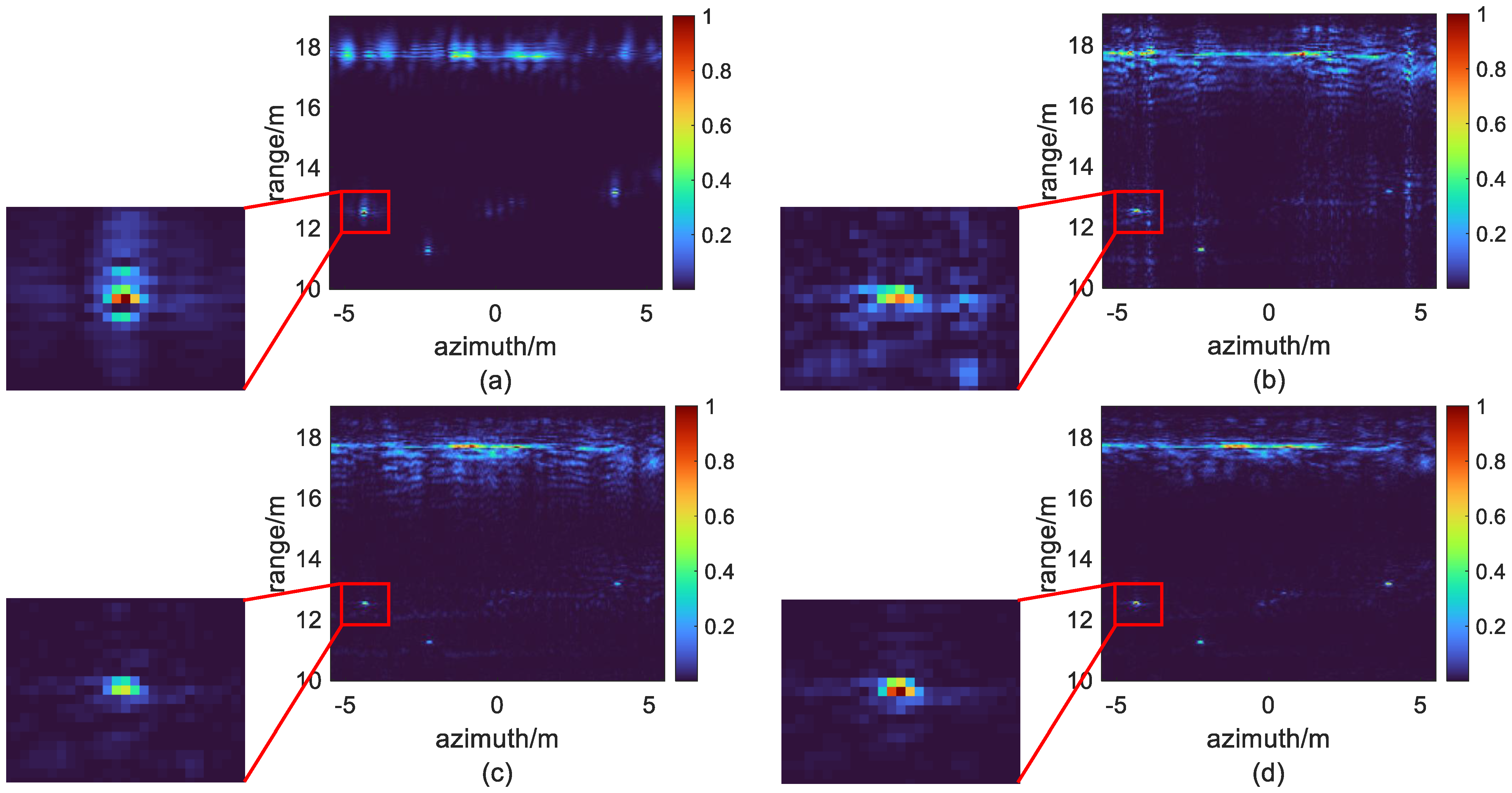
4.2.2. Ringing Suppression Results

As illustrated in Figure 7, the results obtained from the LSE, MVDR, IAA, and the proposed Bayesian method are presented for comparison. The LSE algorithm demonstrates a uniform distribution of ringing on both sides of the target, failing to achieve effective suppression of TDR. In contrast, the MVDR, IAA, and the proposed Bayesian method exhibit significant suppression of TDR, leading to a notable improvement in the range imaging quality of the three corner reflectors. However, while MVDR and IAA show promising results in TDR suppression, they introduce transverse ripples and sidelobes in the reconstructed images, particularly in regions with continuous and complex targets such as the rock and the wall. These artifacts significantly degrade the visual quality and interpretability of the images. On the other hand, the proposed Bayesian algorithm effectively preserves finer details in the scene, with minimal transverse ripples or sidelobes observed, resulting in a cleaner and more accurate representation of the targets.
The performance of the four algorithms, LSE, MVDR, IAA, and the proposed Bayesian method is analyzed in both ideal point target (corner reflector) and continuous target (brick wall) scenarios, highlighting their differences in resolution, ringing suppression, and adaptability. Figure 8 shows the range profile of an ideal point target (point reflector 3). The LSE method exhibits significant main lobe broadening and symmetrically distributed periodic ringing, indicating its inability to effectively suppress TDR as expected. In contrast, MVDR and IAA demonstrate improved main lobe compression and ringing suppression, though they still exhibit low-amplitude transverse ripples in regions far from the main lobe. The Bayesian method achieves comparable performance to the MVDR and IAA methods in terms of main lobe compression, while demonstrating a slight improvement in sidelobe suppression.
For continuous targets, such as a brick wall, the performance differences among the algorithms are further accentuated in Figure 9. The LSE method fails to suppress the ringing artifacts, which split the wall’s reflection into two distinct main peaks and introduce periodic oscillations. In contrast, the MVDR, IAA, and Bayesian methods effectively suppress the main lobe ringing, successfully merging the split peaks into a coherent main lobe. However, due to model mismatch errors, all three methods exhibit residual sidelobes in regions far from the main lobe. Notably, MVDR and IAA produce more pronounced sidelobes compared to the Bayesian approach, likely caused by their sensitivity to scattering heterogeneity in continuous targets. The Bayesian method mitigates this issue through sparse optimization, achieving smoother scattering distributions with fewer sidelobes.
In summary, the proposed method outperforms traditional algorithms in both point and continuous target scenarios, particularly in complex scenes where sparse optimization significantly enhances imaging quality; while MVDR and IAA show improvements in ringing suppression and resolution, they remain sensitive to model errors in continuous targets. The proposed method’s robustness and adaptability make it a suitable solution for impulse SAR imaging, effectively suppressing ringing and improving target fidelity.

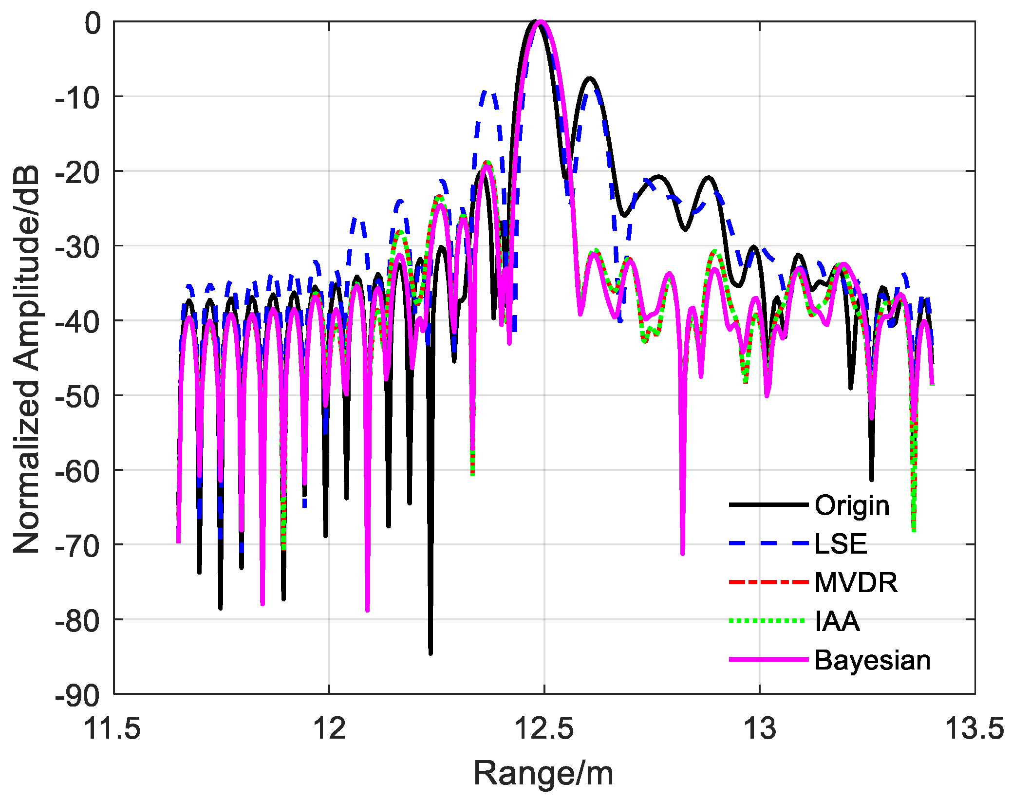
4.2.3. Performance Evaluation

To evaluate the ringing suppression performance, we computed key metrics, including the peak sidelobe ratio (PSLR), the integrated sidelobe ratio (ISLR), and image entropy, as shown in Table 3. The PSLR and ISLR values for MVDR, IAA, and the proposed Bayesian method are significantly lower than those of the original image, indicating effective ringing suppression. The Bayesian method achieves the lowest PSLR and ISLR, demonstrating slightly better performance in suppressing TDR compared to MVDR and IAA.
However, as observed in Figure 7, MVDR and IAA exhibit noticeable model mismatch at the sidelobe positions of the targets, which can be quantified using image entropy. Image entropy is a statistical measure of randomness, which is used to characterize the distribution and dispersion of signal intensity amplitudes within an image [34,35]. Generally, high-entropy enables a well-focused operation [36]. Image entropy can be defined as follows:
E = m = 1 M n = 1 N p ( m , n ) log ( p ( m , n ) )
where the probability distribution function is:
p ( m , n ) = I ( m , n ) m = 1 M n = 1 N I ( m , n )
Figure 10 indicates entropy in different SNRs. From the results, the Bayesian method shows a higher image entropy compared to the original image and LSE, indicating a trade-off between ringing suppression and image quality. This suggests that the Bayesian method achieves superior ringing suppression at the cost of a slight increase in image entropy. In contrast, MVDR and IAA, while effective in suppressing ringing, suffer from more significant model mismatch, as reflected in their higher image entropy values. This analysis highlights the Bayesian method’s ability to balance ringing suppression and image quality, making it a more robust choice for practical applications.
To further validate the practical effectiveness of the proposed method, Table 4 analyzes the computational performance of various ringing suppression algorithms on the aforementioned one-dimensional simulation data and two-dimensional real scene data. As shown in the table, the proposed image-based ringing suppression algorithm demonstrates high efficiency, completing the suppression process for single-frame impulse SAR images within 5 s across different methods, thereby exhibiting strong real-time processing capability. Among the four compared methods, LSE achieves faster computation speed but fails to deliver ringing suppression effects, serving merely as a performance benchmark. The remaining three ringing suppression methods maintain computational durations within the same order of magnitude. Specifically, the proposed Bayesian method requires longer processing time compared to MVDR, yet it shows shorter computation duration than IAA.
In conclusion, the experimental results demonstrate that the Bayesian method outperforms LSE, MVDR, and IAA in suppressing TDR with minimal degradation in image quality, despite a slight increase in image entropy. This trade-off underscores the method’s effectiveness in achieving robust ringing suppression while maintaining acceptable image fidelity. Furthermore, since the proposed method operates directly on SAR images, it achieves exceptionally high computational efficiency, fulfilling the real-time processing requirements critical for practical applications.

5. Conclusions

To address the TDR artifacts induced by UWB antennas in impulse synthetic SAR systems, this study proposes an efficient ringing suppression algorithm grounded in a thorough analysis of the physical mechanisms underlying ringing generation. The proposed method leverages sparse optimization to enhance imaging quality while balancing the trade-off between ringing suppression and image fidelity. Comparative evaluations with traditional algorithms including LSE, MVDR, and IAA demonstrate its superior performance in both ideal point targets and complex continuous targets. Specifically, the Bayesian inspired approach achieves the lowest PSLR and ISLR among all tested methods, confirming its advanced capability in suppressing sidelobes and merging split peaks caused by ringing; while MVDR and IAA exhibit residual model mismatch artifacts in regions far from the main lobe, the proposed method effectively mitigates these issues through structural constraints, resulting in smoother scattering distributions and preserved edge sharpness.
The proposed method induces a regulated rise in image entropy compared to baseline imagery, reflecting a systematic trade-off where controlled information loss is accepted to optimize TDR suppression. This is corroborated by the entropy analysis in Figure 10, where the method maintains a more favorable balance between artifact reduction and information retention than MVDR and IAA. Experimental validation using both numerical simulations and real-world data underscores the algorithm’s robustness in diverse scenarios, from isolated corner reflectors to continuous targets like brick walls.
The success of this method holds significant promise for practical applications in remote sensing, particularly in scenarios requiring high-resolution imaging, such as urban infrastructure monitoring, geological exploration, and disaster assessment. By addressing the persistent challenge of TDR in impulse SAR systems, the proposed framework not only improves image quality but also enhances the reliability of downstream processing tasks, including target detection and classification. Future work will focus on optimizing computational efficiency to further bridge the gap between theoretical performance and real-time implementation. This study advances the field of radar imaging by demonstrating the critical role of physics-driven sparse optimization in resolving artifact suppression challenges, paving the way for more accurate and interpretable SAR-based sensing systems.

Author Contributions

Conceptualization: X.X. and W.L.; Methodology: X.X., W.L. and H.T.; Software: X.X. and W.L.; Validation: C.Z. and T.J.; Formal analysis: X.X. and W.L.; Investigation: C.Z. and T.J.; Resources: L.C., J.L. and X.L.; Data curation: H.T., C.Z. and T.J.; Writing—original draft: X.X.; Writing—review and editing: X.X.; Funding acquisition: H.T. and L.C. All authors have read and agreed to the published version of the manuscript.

Funding

This research was funded by the National Key Research and Development Program of China under grant 2022YFB3901601.

Data Availability Statement

Due to the confidentiality of the project, the datasets used in this article cannot be shared. If necessary, please contact the corresponding author for relevant data and authorization.

Acknowledgments

The authors gratefully acknowledge the anonymous reviewers and editors for their constructive feedback that significantly improved the quality of this paper.

Conflicts of Interest

Author Jie Liu is employed by the 27th Research Institute of China Electronics Technology Group Corporation. All other authors declare no competing financial interests or personal relationships that could influence the work reported in this paper.

Abbreviations

The following abbreviations are used in this manuscript:
UWBultrawideband
SARsynthetic aperture radar
TDRtime-domain ringing
SNRsignal-to-noise ratio
LSEleast squares estimation
MVDRminimum variance distortionless response
IAAiterative adaptive approach
LFMlinear-frequency-modulated
PSFpoint spread function
MAPmaximum a posteriori
LNAslow-noise amplifiers
ADCsanalog-to-digital converters
IMUinertial measuring unit
PRTpulse repetition time
PSLRpeak sidelobe ratio
ISLRintegrated sidelobe ratio

References

  1. Debes, C.; Amin, M.G.; Zoubir, A.M. Target Detection in Single- and Multiple-View Through-the-Wall Radar Imaging. IEEE Trans. Geosci. Remote Sens. 2009, 47, 1349–1361. [Google Scholar] [CrossRef]
  2. Hu, J.; Zhu, G.; Jin, T.; Zhou, Z. Adaptive Through-Wall Indication of Human Target with Different Motions. IEEE Geosci. Remote Sens. Lett. 2014, 11, 911–915. [Google Scholar] [CrossRef]
  3. Hu, J.; Song, Y.; Jin, T.; Lu, B.; Zhu, G.; Zhou, Z. Shadow Effect Mitigation in Indication of Moving Human Behind Wall via MIMO TWIR. IEEE Geosci. Remote Sens. Lett. 2015, 12, 453–457. [Google Scholar] [CrossRef]
  4. Li, J.; Zeng, Z.; Sun, J.; Liu, F. Through-Wall Detection of Human Being’s Movement by UWB Radar. IEEE Geosci. Remote Sens. Lett. 2012, 9, 1079–1083. [Google Scholar] [CrossRef]
  5. Amin, M.G.; Ahmad, F. Change Detection Analysis of Humans Moving Behind Walls. IEEE Trans. Aerosp. Electron. Syst. 2013, 49, 1410–1425. [Google Scholar] [CrossRef]
  6. Wang, K.; Zeng, Z.; Sun, J. Through-Wall Detection of the Moving Paths and Vital Signs of Human Beings. IEEE Geosci. Remote Sens. Lett. 2019, 16, 717–721. [Google Scholar] [CrossRef]
  7. Debes, C.; Riedler, J.; Zoubir, A.M.; Amin, M.G. Adaptive Target Detection With Application to Through-the-Wall Radar Imaging. IEEE Trans. Signal Process. 2010, 58, 5572–5583. [Google Scholar] [CrossRef]
  8. Ali, J.; Abdullah, N.; Yusof, M.; Mohd, E.; Shah, S.M. Ultrawideband Antenna Design for GPR Applications: A Review. Int. J. Adv. Comput. Sci. Appl. 2017, 8, 392–400. [Google Scholar]
  9. Schantz, H.G. The Art and Science of Ultrawideband Antennas; Artech House: Boston, MA, USA, 2015. [Google Scholar]
  10. Rahman, M.; Haider, A.; Naghshvarianjahromi, M. A Systematic Methodology for the Time-Domain Ringing Reduction in UWB Band-Notched Antennas. IEEE Antennas Wirel. Propag. Lett. 2020, 19, 482–486. [Google Scholar] [CrossRef]
  11. Jafari, H.M.; Deen, M.J.; Hranilovic, S.; Nikolova, N.K. A Study of Ultrawideband Antennas for Near-Field Imaging. IEEE Trans. Antennas Propag. 2007, 55, 1184–1188. [Google Scholar] [CrossRef]
  12. Lotfi, P.; Azarmanesh, M.; Soltani, S. Rotatable Dual Band-Notched UWB/Triple-Band WLAN Reconfigurable Antenna. IEEE Antennas Wirel. Propag. Lett. 2013, 12, 104–107. [Google Scholar] [CrossRef]
  13. Liang, J.; Chiau, C.; Chen, X.; Parini, C. Study of a printed circular disc monopole antenna for UWB systems. IEEE Trans. Antennas Propag. 2005, 53, 3500–3504. [Google Scholar] [CrossRef]
  14. Kim, K.; Scott, W. Design of a resistively loaded vee dipole for ultrawide-band ground-penetrating Radar applications. IEEE Trans. Antennas Propag. 2005, 53, 2525–2532. [Google Scholar] [CrossRef]
  15. Jin, Y.; Chen, J.; Liang, B.; Yang, D.; Xing, M.; Liu, L. First Demonstration of Using Signal Processing Approach to Suppress Signal Ringing in Impulse UWB Through-Wall Radar. IEEE Geosci. Remote Sens. Lett. 2022, 19, 1–5. [Google Scholar] [CrossRef]
  16. Capon, J. High-resolution frequency-wavenumber spectrum analysis. Proc. IEEE 1969, 57, 1408–1418. [Google Scholar] [CrossRef]
  17. Lacoss, R.T. Data adaptive spectral analysis methods. Geophysics 1971, 36, 661–675. [Google Scholar] [CrossRef]
  18. Stoica, P.; Li, J.; He, H. Spectral Analysis of Nonuniformly Sampled Data: A New Approach Versus the Periodogram. IEEE Trans. Signal Process. 2009, 57, 843–858. [Google Scholar] [CrossRef]
  19. Zhang, Y.; Zhang, Y.; Huang, Y.; Li, W.; Yang, J. Angular Superresolution for Scanning Radar with Improved Regularized Iterative Adaptive Approach. IEEE Geosci. Remote Sens. Lett. 2016, 13, 846–850. [Google Scholar] [CrossRef]
  20. Li, Y.; Liu, J.; Jiang, X.; Huang, X. Angular Superresol for Signal Model in Coherent Scanning Radars. IEEE Trans. Aerosp. Electron. Syst. 2019, 55, 3103–3116. [Google Scholar] [CrossRef]
  21. Zhang, Y.; Jakobsson, A.; Zhang, Y.; Huang, Y.; Yang, J. Wideband Sparse Reconstruction for Scanning Radar. IEEE Trans. Geosci. Remote Sens. 2018, 56, 6055–6068. [Google Scholar] [CrossRef]
  22. Pan, C. Gibbs phenomenon removal and digital filtering directly through the fast Fourier transform. IEEE Trans. Signal Process. 2001, 49, 444–448. [Google Scholar] [CrossRef]
  23. Lustig, M.; Donoho, D.; Pauly, J.M. Sparse MRI: The application of compressed sensing for rapid MR imaging. Magn. Reson. Med. 2007, 58, 1182–1195. [Google Scholar] [CrossRef] [PubMed]
  24. Block, K.T.; Uecker, M.; Frahm, J. Undersampled radial MRI with multiple coils. Iterative image reconstruction using a total variation constraint. Magn. Reson. Med. 2007, 57, 1086–1098. [Google Scholar] [CrossRef]
  25. Amin, M.G. Through-the-Wall Radar Imaging; CRC Press: Boca Raton, FL, USA, 2017. [Google Scholar]
  26. Guru, B.S.; Hiziroglu, H.R. Electromagnetic Field Theory Fundamentals; Cambridge University Press: Cambridge, UK, 2009. [Google Scholar]
  27. Kannadhasan, S.; Nagarajan, R. Performance Improvement of Slot Antenna Using Various Parameters and Band Pass Filter. In Proceedings of the 2018 International Conference on Circuits and Systems in Digital Enterprise Technology (ICCSDET), Kottayam, India, 21–22 December 2018; pp. 1–4. [Google Scholar] [CrossRef]
  28. Wu, C.H.; Wang, C.H.; Chen, S.Y.; Chen, C.H. Balanced-to-Unbalanced Bandpass Filters and the Antenna Application. IEEE Trans. Microw. Theory Tech. 2008, 56, 2474–2482. [Google Scholar] [CrossRef]
  29. Zhou, X.P.; Wei, G.H.; Wu, S.L.; Liu, Y. Overview of imaging algorithm based on impulse radar. Xi Tong Gong Cheng Yu Dian Zi Ji Shu/Syst. Eng. Electron. 2014, 36, 1081–1087. [Google Scholar]
  30. Lv, T.g.; Lu, Z.l. The analysis of the azimuth resolution of impulse signal SAR. ACTA Electron. Sin. 2000, 28, 40–43. [Google Scholar]
  31. Zhang, Y.; Tuo, X.; Huang, Y.; Yang, J. A TV Forward-Looking Super-Resolution Imaging Method Based on TSVD Strategy for Scanning Radar. IEEE Trans. Geosci. Remote Sens. 2020, 58, 4517–4528. [Google Scholar] [CrossRef]
  32. Cetin, M.; Karl, W. Feature-enhanced synthetic aperture radar image formation based on nonquadratic regularization. IEEE Trans. Image Process. 2001, 10, 623–631. [Google Scholar] [CrossRef]
  33. Xu, G.; Xing, M.D.; Xia, X.G.; Zhang, L.; Liu, Y.Y.; Bao, Z. Sparse Regularization of Interferometric Phase and Amplitude for InSAR Image Formation Based on Bayesian Representation. IEEE Trans. Geosci. Remote Sens. 2015, 53, 2123–2136. [Google Scholar] [CrossRef]
  34. Wu, K.C. Bringing Order to Disorder: Is Image Entropy the Answer? JACC Cardiovasc. Imaging 2019, 12, 1185–1187. [Google Scholar] [CrossRef]
  35. Bai, Z.; Liu, Z.; He, P. SAR image target segmentation based on entropy maximization and morphology. J. Syst. Eng. Electron. 2004, 15, 484–487. [Google Scholar]
  36. Nobre, R.H.; Rodrigues, F.A.; Marques, R.C.; Nobre, J.S.; Neto, J.F.; Medeiros, F.N. SAR image segmentation with Renyi’s entropy. IEEE Signal Process. Lett. 2016, 23, 1551–1555. [Google Scholar] [CrossRef]
Figure 1. (a) Original impulse signal. (b) Impulse signal affected by multiple reflections. (c) Impulse signal affected by low-frequency losses. (d) Impulse signal affected by multiple reflections and low-frequency losses.
Remotesensing 17 01455 g001
Figure 2. Illustration of impulse signal ringing deconvolution model.
Remotesensing 17 01455 g002
Figure 3. (a) True original scene of point target. (b) Impulse signal with ringing.
Remotesensing 17 01455 g003
Figure 4. Results of different deconvolution methods.
Remotesensing 17 01455 g004
Figure 5. Real scene, target distribution map and 2D SAR imaging result.
Remotesensing 17 01455 g005
Figure 6. Automotive impulse SAR system used in the experiment.
Remotesensing 17 01455 g006
Figure 7. Ringing suppression results. (a) LSE. (b) MVDR. (c) IAA. (d) Bayesian.
Remotesensing 17 01455 g007
Figure 8. Range profile of ideal point target (corner reflector 3).
Remotesensing 17 01455 g008
Figure 9. Range profile of continuous target (brick wall).
Remotesensing 17 01455 g009
Figure 10. Entropy curves under different SNRs.
Remotesensing 17 01455 g010
Table 1. Simulation parameters.
ParametersValuesParametersValues
Raise time T r 0.4 nsDecay time T d 0.5 ns
Sampling rate F s 5 GHzDuration T20 ns
Time delay t d 1 nsNumber of reflection K2
Reflection coefficient1 ρ 1 0.5Reflection coefficient2 ρ 2 0.2
Table 2. Parameters of impulse SAR system.
ParametersValuesParametersValues
Platform velocity4 m/sAzimuth beam40°
Sampling rate5 GHzEffective pulse width0.25 ns
Pulse repetition time200 μ sWorking frequency0.4−2.4 GHz
Table 3. Performances of different ringing suppression methods.
OriginLSEMVDRIAABayesian
PSLR (dB)−7.6145−8.5419−18.7809−18.6574−19.3318
ISLR (dB)−6.8603−5.7687−18.3457−18.7191−19.0273
Table 4. Efficiencies of different ringing suppression methods.
LSEMVDRIAABayesian
Simulation data0.0127 s0.0799 s0.2385 s0.1947 s
Real scene data0.0331 s1.2754 s4.1803 s2.6297 s
Disclaimer/Publisher’s Note: The statements, opinions and data contained in all publications are solely those of the individual author(s) and contributor(s) and not of MDPI and/or the editor(s). MDPI and/or the editor(s) disclaim responsibility for any injury to people or property resulting from any ideas, methods, instructions or products referred to in the content.

