1. Introduction
Recent advancements in satellite technology, along with decreased launch costs and the commercialization of low-Earth-orbit (LEO) constellations, have emerged as key driving forces behind the development of mega-constellations. There is a growing trend in the building of LEO constellations worldwide to deliver global broadband Internet services [
1,
2]. LEO satellites provide signals with high temporal resolution, extending their applications to the fields of position, navigation, and timing (PNT) and remote sensing. Many studies have demonstrated the potential of LEO satellites as promising and reliable sources for navigation [
3,
4]. The advantages of LEO satellite navigation include strong signal strength, favorable dilution of precision (DOP) factors, fast geometric changes that enhance precise point positioning (PPP) performance, and easy collaboration with the global navigation satellite system (GNSS) [
5,
6]. These advantages compensate for the limitations of GNSS signals in environments characterized by deep attenuation and interference, fostering the development of integrated navigation and communication (INAC) technology based on broadband modulation. An INAC system can effectively reduce the costs associated with constellation construction; thus, the implementation of navigation based on broadband modulation has become an important research area [
7].
Orthogonal frequency division multiplexing (OFDM) offers high spectral efficiency, effective multipath mitigation, and a large mean square bandwidth [
8,
9], making it widely used in wireless communication and INAC systems. The long-term evolution (LTE) system independently performs positioning using a positioning reference signal (PRS) based on OFDM, which is located in the positioning subframes, and the new radio (NR) further optimizes the PRS for better positioning performance [
10,
11]. However, there are severe near–far effects between the positioning signals from different base stations, which make the signals from far base stations more difficult to receive, resulting in a positioning accuracy of a few tens of meters. This is not enough for the high-precision positioning of future applications [
12,
13]. To mitigate the near–far effects, Yin proposed a multi-scale non-orthogonal multiple access (MS-NOMA) scheme [
14]. In this scheme, the navigation signal is modulated using OFDM, and employs different pseudo-random noise (PRN) code sequences across various subcarriers to allocate resources to multiple positioning users. However, it imposes a limitation on the number of positioning users. Deng proposed a time code division-OFDM (TC-OFDM) signal [
15,
16]. TC-OFDM integrates OFDM for communication with binary phase shift keying (BPSK) modulation for navigation, both of which share the same frequency band. However, the spectral fluctuations and high out-of-band (OOB) emissions associated with the BPSK signal lead to interference with the OFDM demodulation, adversely affecting signals in adjacent frequency bands. For the LEO satellite INAC system, Wang proposed a Zadoff–Chu NOMA (ZC-NOMA) scheme [
17]. ZC-NOMA superimposes low-power ZC sequences onto the communication subcarriers of OFDM to mitigate the Doppler effect on time-of-arriving (TOA) estimation. However, there is also MI between the communication symbols and the ZC sequences, which limits performance in massive LEO satellite positioning scenarios. Furthermore, the communication reliability of OFDM-based signals is compromised in high-mobility channels due to Doppler spread, which induces inter-carrier interference (ICI) and results in an increased bit error rate (BER).
Orthogonal time–frequency space (OTFS) modulation is specifically designed for reliable communication in high-mobility channels. It multiplexes information symbols over two-dimensional orthogonal basis functions in the delay–Doppler (DD) domain [
18], converting a fast time-varying multipath channel into a sparse and slow time-varying channel, thereby facilitating low-complexity detection and channel estimation [
19]. Consequently, OTFS is regarded as a candidate waveform for 6G, and has been utilized in the design of INAC schemes [
20]. In recent years, research on OTFS has focused on communication areas such as waveform design [
21], channel estimation [
22,
23], detection [
24], and diversity [
25,
26] techniques. Refs. [
27,
28,
29] studied the random access, spatial correlation, and downlink outage probability of OTFS in LEO satellite communication systems. Ref. [
30] designed a realizable DD orthogonal pulse and proposed orthogonal delay–Doppler division multiplexing modulation (ODDM), achieving lower OOB emission and BER in practical systems. In addition, integrated sensing and communication (ISAC) based on OTFS has also received attention [
31,
32,
33,
34]. The main purpose of these works was to enable localization, velocimetry, imaging, detection, etc., of the environment or targets, rather than acquiring time and space information about the users themselves. Specifically, the ISAC scheme for the Internet of Things (IoT) in [
32] achieves low-complexity, high-precision target parameter estimation under the assumption of perfect delay and frequency synchronization. In contrast, navigation receivers do not transmit signals, but synchronize and localize themselves by passively receiving line-of-sight (LOS) signals from satellites [
35]. For the same reason, the schemes in [
33,
34] for target detection and tracking in multi-antenna radar receivers are not suitable as PNT solutions for single-antenna navigation receivers. In [
31], a random-padded OTFS (RP-OTFSM) is proposed to improve radar sensing performance by replacing the impulse pilot surrounded by zero guard zone by random-value pilot with a cyclic prefix, but it is not designed to provide continuous and accurate PNT services with dedicated broadcast signals. In terms of research on OTFS-based INAC, Ref. [
36] utilizes the distance and velocity information estimated from the delay–Doppler channel matrix of the OTFS system for positioning. However, the signal does not incorporate a dedicated navigation component, resulting in a limited number of navigation users. Ref. [
37] superimposes the alternating binary offset carrier (AltBOC) modulated navigation message with the quadrature amplitude-modulated communication data to enhance the reliability of data transmission. Additionally, a time-domain PRN sequence for channel estimation and positioning is inserted before the OTFS frame, and we refer to this scheme as PN-OTFS later. However, due to the successive interference cancelation (SIC) employed to separate navigation messages from communication data, the computational burden on the receiver to process multi-satellite signals is substantial. Furthermore, the proposed signals in [
36,
37] must process the entire bandwidth to demodulate the data used for navigation, which undoubtedly increases the processing burden on the navigation receiver.
In summary, the existing INAC waveforms still face the following challenges: (1) A high-power communication signal impacts the correlation function of the navigation signal in waveforms that share frequency bands, thereby limiting ranging accuracy. (2) The complexity of receiving navigation signals is quite high. Navigation receivers typically process signals from dozens of satellites [
38], while broadband LEO satellites usually operate in the Ka, Ku, and C frequency bands, with signal bandwidths exceeding hundreds of megahertz, imposing a significant burden on signal processing. (3) Data transmission reliability is poor in high-mobility channels. OFDM-based signals experience severe ICI in high-mobility channels, leading to a significant increase in BER.
We focus on the design of an INAC waveform based on OTFS to address these three issues, inspiring LEO PNT applications while ensuring communication reliability in high-mobility channels. Specifically, the contributions of this paper include the following four aspects:
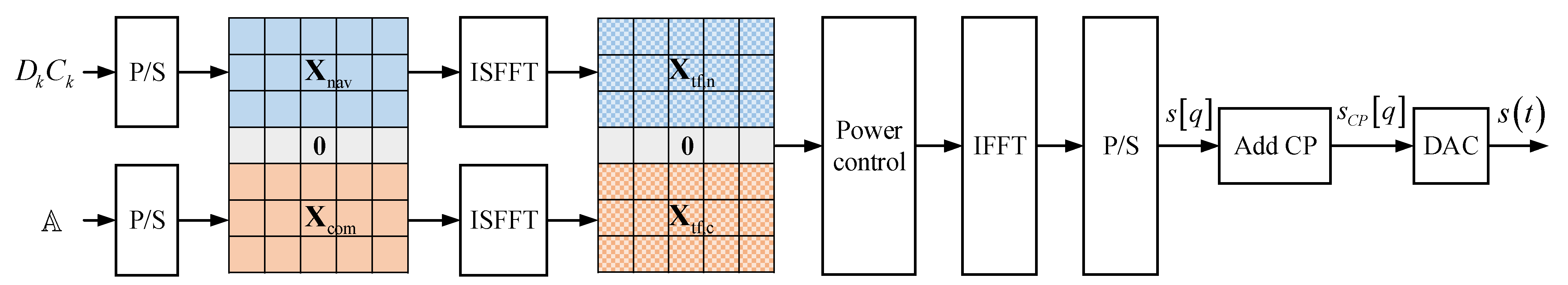
A delay–Doppler block division multiplexing (DDBDM) waveform is proposed. The navigation PRN codes and communication data are modulated on two-dimensional orthogonal basis functions in the DD domain, and this orthogonality limits MI, making it easier to improve ranging accuracy. Meanwhile, data transmission in the DD domain ensures reliability of communication.
By independently transforming navigation and communication signals across different DD blocks, they are separated in the frequency domain. This allows users to receive the navigation signal independently, without the loss of useful power, thereby reducing the signal processing overhead. Additionally, the dedicated broadcast signal enables continuous and passive positioning, facilitating easier collaboration with the GNSS.
We propose a navigation receiver architecture for DDBDM that extracts continuous and accurate measurements. The proposed acquisition and tracking structure is compatible with traditional navigation receivers, facilitating the simplification of receiver design and reducing the development costs for user equipment (UE). Furthermore, we implement a software-defined radio (SDR) prototype of the INAC system to validate the design of the proposed architecture.
Simulation results indicate that the proposed waveform exhibits superior comprehensive performance compared to existing schemes. The ranging accuracy of DDBDM is higher than that of ZC-NOMA, PN-OTFS, and RP-OTFSM, with the same bandwidth. Even with an 80% reduction in the signal bandwidth of DDBDM, the ranging accuracy remains higher than that of PN-OTFS and RP-OTFSM, and it also surpasses that of ZC-NOMA when the signal-to-noise ratio (SNR) is greater than 10 dB and the communication-to-navigation power ratio (CNPR) is 30 dB. In LEO high-mobility multipath channels, DDBDM has a lower BER compared to the other schemes, thus providing reliable communication. It also aids in the transmission of broadcast messages to reduce the time to first fix (TTFF) for navigation receivers and to provide information augmentation services.
The remainder of this paper is organized as follows.
Section 2 introduces the system model and elucidates the problem of the original OTFS.
Section 3 introduces the proposed waveform and elaborates on the steps of signal generation.
Section 4 proposes the navigation signal processing method.
Section 5 evaluates the navigation and communication performance and implements the prototype of the INAC system. Finally, the paper is summarized in
Section 6.
4. Navigation Signal Processing
This section proposes the navigation receiver architecture for DDBDM, which primarily consists of acquisition and tracking modules. The architecture enables continuous and accurate measurement of delay and Doppler frequency for navigation. Additionally, its design, similar to that of traditional navigation receivers, helps to reduce the development cost and facilitate upgrades of UE.
4.1. Signal Acquisition
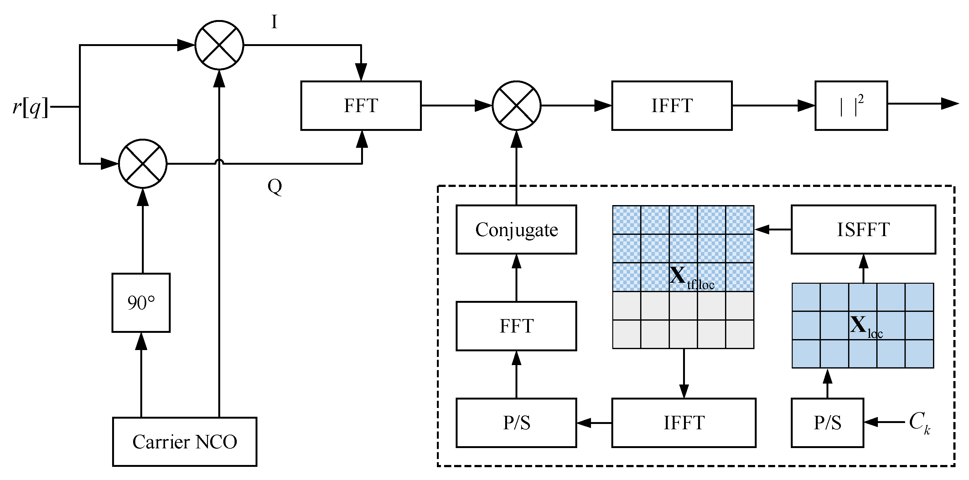
In the signal acquisition stage, only coarse estimations of the delay and Doppler frequency need to be provided. The received continuous-time baseband signal is denoted as r(t), and the discrete-time samples r[q] obtained after the analog-to-digital converter (ADC) serve as the input to the acquisition module.
The block diagram of the DDBDM signal acquisition using the parallel code-phase search (PCS) method is shown in
Figure 5. This structure is similar to that of a traditional navigation receiver, with the difference being the generation of the local replica, namely the part enclosed in the dashed box. The local replica in TF domain is as follows:
where
is the local PRN code in the DD domain defined in (5),
and satisfies
, and the zero padding in (19) is used to oversample the PRN code [
46]. Therefore, the sampling rate
is an integer multiple of the subcarrier spacing. Since the sampling rate no longer needs to be greater than the entire signal bandwidth
, the signal processing overhead for navigation is reduced.
Then, IFFT and P/S operations are employed to generate the oversampled local replica:
The discrete-time local replica in the above equation can be pre-stored in the receiver, without the necessity for real-time generation.
The orthogonality of the basis functions and the periodicity of the PRN code enable receivers to estimate the delay and Doppler frequency in the time domain. The correlation function between the cyclic shift and the conjugate version of the received signal and the local replica is as follows:
where the number of signal samples in one period is
. The correlation values at the delay of each sample in the above equation can be quickly calculated using the FFT/IFFT-based PCS method:
where
denotes the Hadamard product operator.
The carrier numerically controlled oscillator (NCO) is used to adjust the Doppler frequency of the received signal. After the cross-correlation operations for all possible frequency bins, a correlation value matrix is generated. The maximum value obtained from the incoherent combination of the real and imaginary parts of the elements in the matrix is then compared with the detection threshold to determine whether the signal is present [
50].
If the signal is detected, the maximum likelihood (ML) estimate of the delay can be calculated by finding the peak value of the correlation corresponding to the current frequency bin:
Finally, since the accuracy of the frequency bin determined during the signal detection process typically does not meet the precision for initializing the tracking loop, a fine Doppler frequency
can be estimated using methods such as spectral analysis [
51].
4.2. Signal Tracking
In the signal tracking stage, the acquisition results are first used for initialization, followed by continuous processing of the navigation signals to obtain accurate measurements of delay and Doppler frequency. The proposed tracking module includes a frequency-locked loop-assisted phase-locked loop (PLL) and a carrier-aided delay-locked loop (DLL).
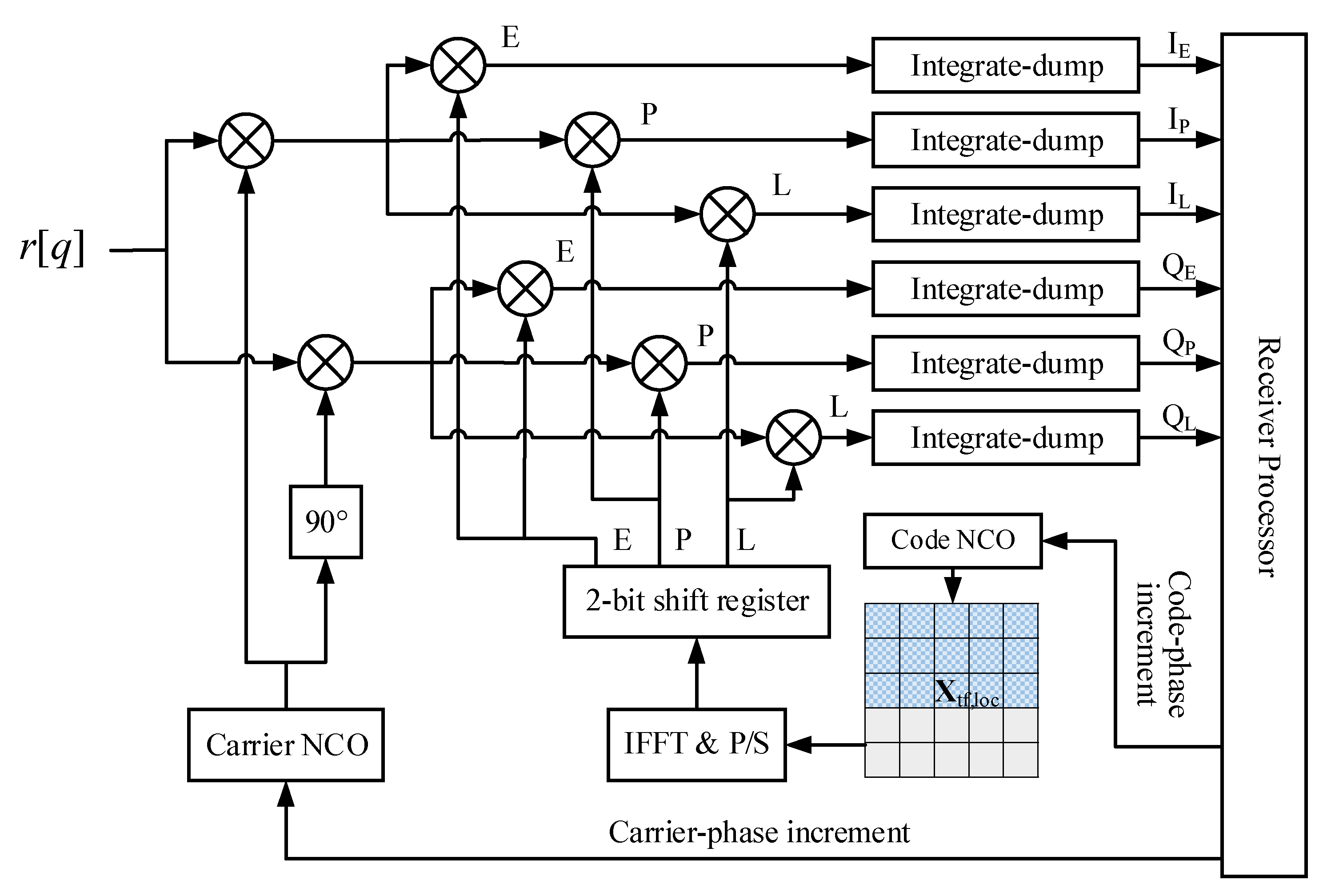
Figure 6 shows the block diagram of DDBDM signal tracking. As can be observed from the Figure, most of the components of the tracking loop are the same as in a traditional navigation receiver, except for the generation of local replicas. Specifically, in contrast to GNSS signals that generate code replicas in the time domain, DDBDM is in the TF domain (DD to TF domain can be performed offline), and requires an additional modulation process, i.e., the IFFT and P/S part in the figure. This no doubt increases the computational overhead, which is one of the reasons why this paper considers the receival of part of the signal bandwidth.
In the tracking process with the DLL, it is necessary to simultaneously generate local replicas for the early, prompt, and late branches, and then the complex correlation values are computed through the integration and dump operation. The general form of the correlation values parameterized by Λ is as follows:
Assuming d is the early–late spacing of the DLL, the early, prompt, and late correlation values can be produced by setting Λ to be −d/2, 0, and d/2, respectively.
The DDBDM signal has in-phase and quadrature components, so the correlation values from both channels are combined with the same weighting to form the composite tracking error estimate, which continuously steers the shared NCO for both channels. For the PLL, the carrier phase error using an arctangent phase discriminator is as follows:
where
For the DLL, the code phase error using the noncoherent early–late processing (NELP) discriminator is as follows:
where
The subscripts E, P, and L represent the early, prompt, and late correlation values, respectively. The subscripts Re and Im represent the real and imaginary parts of the correlation values, respectively.
Finally, the navigation receiver calculates the position, velocity, and clock bias of UE using the measurements and the navigation messages demodulated by the tracking loop. It is worth noting that the CP of the received signal has little impact on the main lobe of the ACF [
52]; it could be considered part of the time-domain signal, aiming to utilize as much energy as possible for correlation.
5. Performance Evaluation
This section evaluates the navigation and communication performance of DDBDM, while comparing it with ZC-NOMA [
17], PN-OTFS [
37], and TFBDM (time–frequency block division multiplexing). The first two are INAC schemes designed for LEO satellites, while TFBDM uses an OFDM-based TF block structure similar to DDBDM. Moreover, to compare the performance of DDBDM more generally, we also use RP-OTFSM in the ISAC system as a benchmark [
31], since it uses known random pilot, and thus may be used as the signal for LEO satellites. Finally, an INAC system prototype, based on SDR, is implemented, and it is used to verify the proposed waveform and navigation receiver architecture.
5.1. Parameter Setup
The system simulation parameters were selected from the LEO-based non-terrestrial networks (NTN) scenario (C2&D2), specified by the third-generation partnership project (3GPP) [
53,
54]. The parameters are summarized in
Table 2, where the subcarrier spacing is Δ
f = 120 kHz, the total number of subcarriers (delay bins) is
M = 1024, and the number of time slots (Doppler bins) is
N = 16. The number of zero-padding subcarriers is
Mp = 24, and the number of subcarriers that can be allocated to navigation and communication is
Mn +
Mc = 1000. The signal frame duration is
NT = 0.133 ms. The duration of the CP should be greater than the maximum delay spread of the multipath channel given in
Table 3, set to
TCP = 1.482 μs. The navigation message and communication data mapping are BPSK and 4QAM, respectively. The satellite communication channel adopts the tapped delay line (TDL) model. The signal strength in the multiple satellites scenario is based on the actual OneWeb constellation at an orbital altitude of 1200 km, with a user longitude of 112.99° and latitude of 28.22°.
The power allocation of the navigation and communication signals has a significant impact on the performance of the INAC signal. In this paper, we define the communication-to-navigation power ratio (CNPR) as the indicator of power allocation:
For ease of analysis, the power of the navigation and communication subcarriers is equally distributed separately. The larger the CNPR, the higher the power allocated to the communication subcarriers. To fairly compare the performance between DDBDM, ZC-NOMA, and PN-OTFS, we evaluate their performance with the same SNR of the received INAC signal.
5.2. Ranging Accuracy
In this section, we first evaluate the ranging accuracy of DDBDM under different conditions, based on the theoretical expressions, and then verify the consistency between the theoretical and simulation results by Monte Carlo simulation. The ranging accuracy of DDBDM can be assessed based on the code tracking accuracy of the DLL, using the NELP discriminator [
55]:
where
is the equivalent noise bandwidth,
is the coherent integration time,
is the front-end bandwidth of the receiver, and
d is the early–late spacing of the correlator.
is the received power of the navigation signal, where
is the channel coefficient,
is the PSD of the environmental noise,
is the normalized PSD of the navigation signal, and
and
are the power and normalized PSD of the interference signal, respectively. The ranging accuracy of ZC-NOMA is also fairly compared using the above equation, as it has a continuous navigation signal. PN-OTFS and RP-OTFSM use a discontinuous PRN preamble or pilot for positioning, so their ranging accuracy is assessed based on the code tracking accuracy of the open-loop estimator using the NELP discriminator [
55,
56]. We discuss an SNR range from −6 dB to 30 dB. The carrier power-to-noise density ratio (
C/
N0) of the navigation signal is 44.8 dB∙Hz at SNR = −6 dB and CNPR = 30 dB, which is equivalent to the power level of GNSS signals. Due to the low orbital altitude of LEO satellites, it is easier to increase the SNR of the received signal.
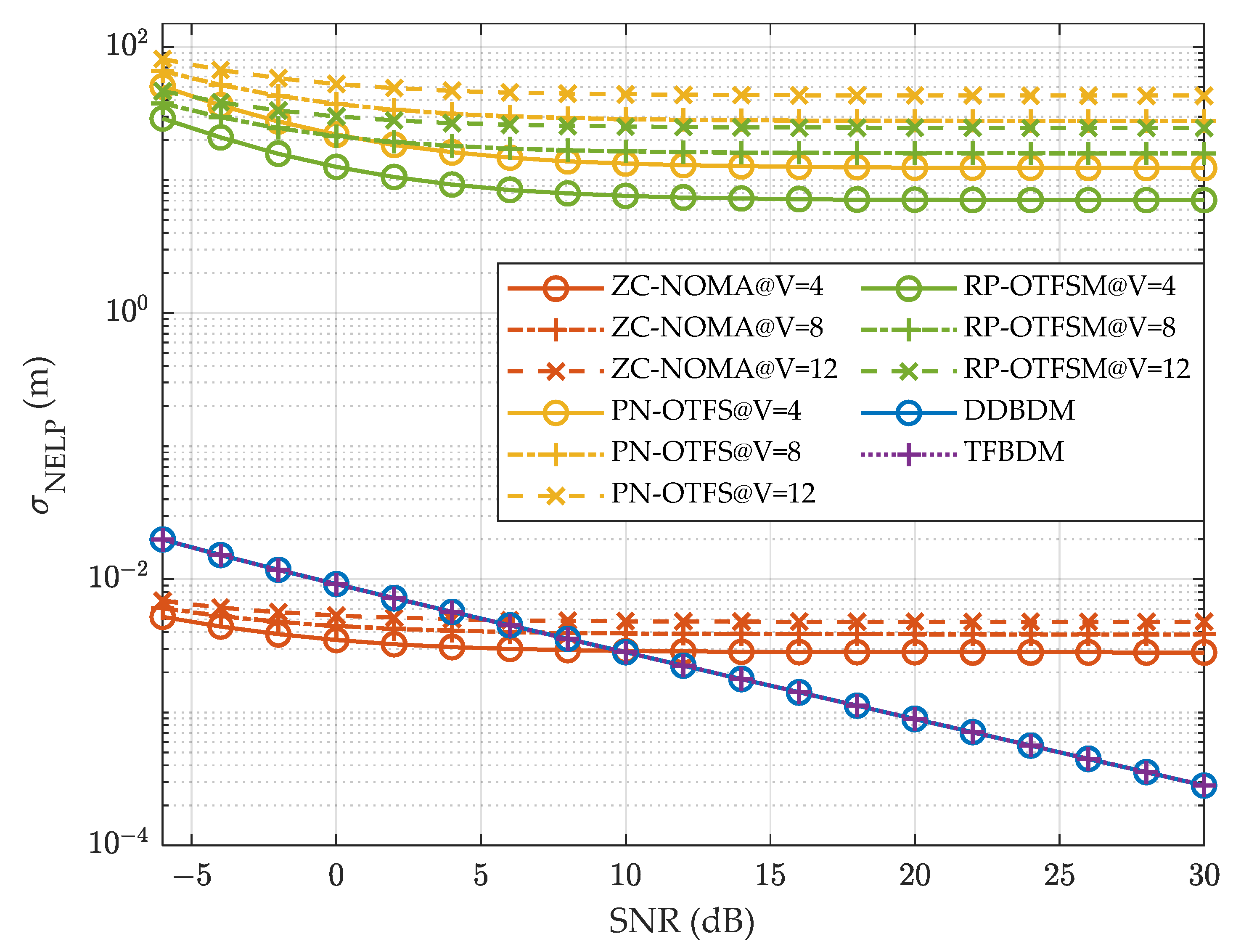
Firstly, we analyze the effect of the number of visible satellites V on the ranging accuracy. In this case,
V is set to 4, 8, and 12, respectively, and CNPR = 30 dB. The navigation signal bandwidth is 24 MHz for both DDBDM and TFBDM, and 120 MHz for ZC-NOMA, PN-OTFS, and RP-OTFSM. The tracking loop parameters are
BL = 0.2 Hz,
Tcoh = 0.133 ms, and
d = 0.5 chip.
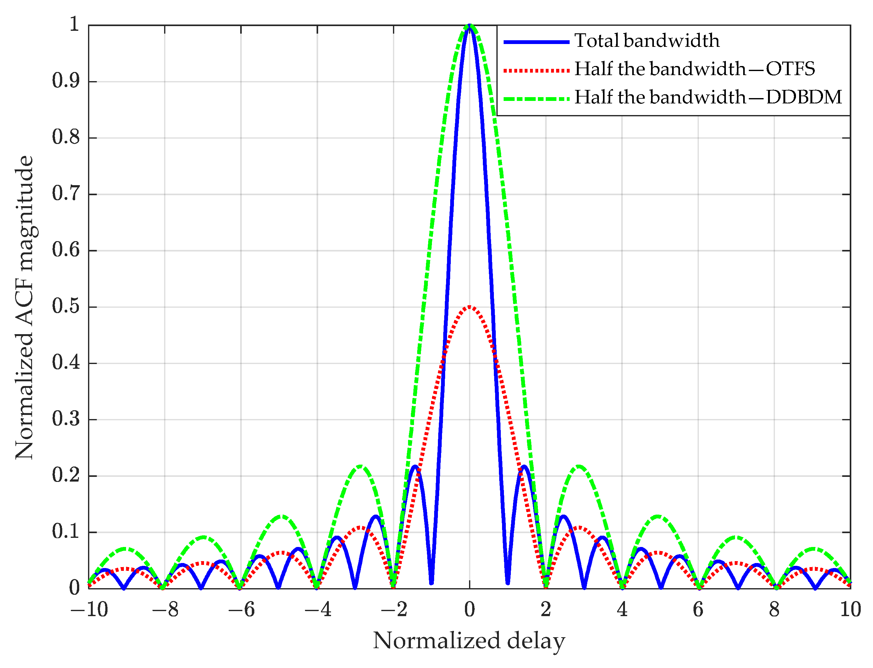
Figure 7 shows the curves of ranging accuracy for the five INAC schemes as a function of the SNR. It can be seen that the ranging accuracies of ZC-NOMA, PN-OTFS, and RP-OTFSM all decrease with the number of visible satellites, and do not improve significantly with the increase in SNR. This is because the navigation signals of the three schemes are subject to interference from communication signals from other satellites in a multi-satellite scenario, and ZC-NOMA, in particular, additionally receives interference with the communication signal from the same satellite. Therefore, the more visible satellites there are, the stronger the power of the interference signals, and the increase in SNR also raises the power of the communication signals acting as interference, which limits the improvement in ranging accuracy. In contrast, the ranging accuracy of DDBDM and TFBDM is almost independent of the number of visible satellites, thanks to the separation of the navigation and communication subcarriers and the employment of CDMA between the navigation signals from different satellites. For the sake of clarity of the Figure, we no longer distinguish their ranging accuracies at different numbers of visible satellites. The navigation signals of DDBDM and TFDBM have similar PSDs, so their ranging accuracies are the same, and are always higher than those of PN-OTFS and RP-OTFSM. The ranging accuracy of DDBDM surpasses that of the ZC-NOMA, with a larger bandwidth if the SNR exceeds 10 dB. This indicates that DDBDM has low MI, making it easier to improve the ranging accuracy.
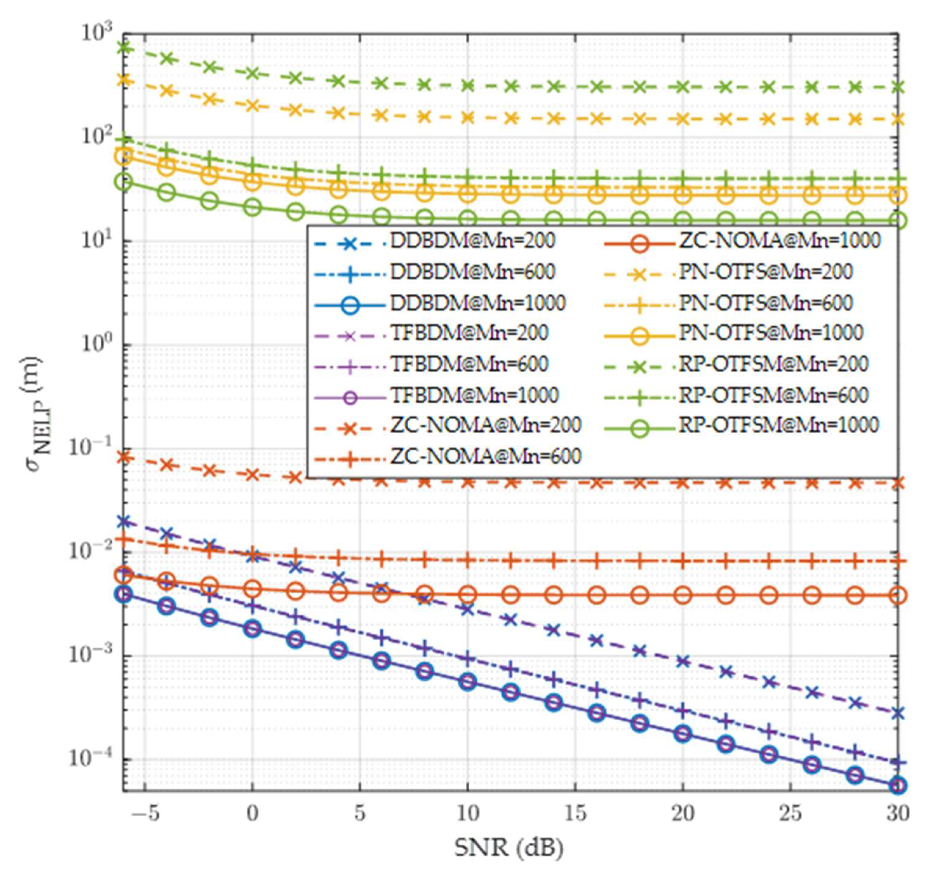
Secondly, we evaluate the ranging accuracy of the five schemes with different received navigation signal bandwidths. The number of navigation subcarriers
Mn is set to 200, 600, and 1000, with the corresponding navigation signal bandwidth determined based on
Br =
MnΔ
f. V = 8, CNPR = 30 dB, and the other parameters remain unchanged.
Figure 8 shows the curves of ranging accuracy as a function of the SNR under different navigation signal bandwidths. The results indicate that DDBDM and TFBDM have the highest ranging accuracy with the same bandwidth. Even when
Mn = 200, the ranging accuracy of DDBDM is still significantly higher than that of PN-OTFS and RP-OTFSM with
Mn = 1000, and it also exceeds that of ZC-NOMA when the SNR is greater than 7 dB, a condition that is easily met in LEO scenarios. The results imply that to achieve the same or higher ranging accuracy, the navigation signal bandwidth of DDBDM can be reduced by 80% compared to ZC-NOMA, PN-OTFS, and RP-OTFSM, mitigating the signal processing burden on the navigation receiver. This is supported by the fact that DDBDM has both a dedicated broadcast signal, allowing continuous tracking of the signal, and a very low MI. In addition, the ranging accuracy of RP-OTFSM is slightly higher than that of PN-OTFS, thanks to the fact that the pilot used for ranging in RP-OTFSM has a larger mean square bandwidth than that of the time-domain PN preamble [
8,
42]. Since PN-OTFS and RP-OTFSM do not have a dedicated broadcast signal component, the ranging accuracy of their open-loop estimators is significantly lower than that of DDBDM, TFBDM, and ZC-NOMA.
Subsequently, we discuss the impact of different power allocations on ranging accuracy. With V = 8 and SNR = 20 dB, the remaining parameters are consistent with those in
Figure 7.
Figure 9 illustrates that as the CNPR increases, the ranging accuracy of all signals decreases, because the power is used more for communication rather than for navigation. Under the condition of a fixed SNR, the ranging accuracy curves for the five schemes do not intersect. DDBDM and TFBDM always have the highest ranging accuracy, while RP-OTFSM and PN-OTFS are worse because they are unable to perform continuous tracking. This is consistent with the previous results.
Finally, we verify the consistency of the theoretical analysis with the simulation. The Monte Carlo simulation uses the tracking loop given in
Figure 6, with the loop parameters
BL = 0.2 Hz,
Tcoh = 0.133 ms, and
d = 0.5 chip. The tracking loop conforms to the generalized structure specified in [
55], and thus allows for evaluation with the theoretical results given in (30). The number of navigation subcarriers of DDBDM is set to 200 and 600, the CNPR is set to 20 and 30, and each point corresponds to 10
4 periods of signal processing. The ranging accuracy is statistically derived as shown in
Figure 10. THE and SIM in the Figure represent the theoretical and simulation results for the given conditions, respectively. It can be observed that under different navigation signal bandwidths and power allocation conditions, the ranging accuracy of the simulation agrees well with the theoretical results in general, which suggests that the assessment of the ranging accuracy using (30) is justified.
From the above discussion, DDBDM offers excellent navigation performance in the scenario of the massive LEO satellites. The low MI of DDBDM ensures that its ranging accuracy effectively improves as the SNR of the INAC signal increases, and its block structure makes it virtually unaffected by communication signals from other satellites. Additionally, the separation of the navigation and communication subcarriers of DDBDM makes the signal processing overhead of the navigation receiver much lower than that of other schemes, making it easier to collaborate with the GNSS to enhance PNT service.
5.3. Data Transmission Reliability
The reliability of data transmission not only affects the quality of service for broadband communication, but is also crucial for quickly receiving navigation messages and high-precision correction parameters in PNT applications. It is usually evaluated by the BER. Therefore, we compare the BER performance of different signals under the same received SNR and the amount of transmitted data. The BER performance depends on the SNR with the determined modulation and coding scheme. The actual SNR of the communication signal of satellite
i is calculated as follows:
where
denotes the channel coefficient on the
k-th subcarrier from satellite
i to the UE link, including antenna gain, free space propagation loss, shadow fading, and other effects.
Channel estimation and signal detection algorithms are not the focus of this work, so ideal channel estimation is used here, and a linear minimum mean square error (LMMSE) detector is employed [
57]. Meanwhile, the number of visible satellites discussed here is V = 1, as the communication receivers could mitigate the impact of signals from other satellites using SIC. Due to the Doppler frequency of the Ka-band signal caused by the dynamic of the satellite far exceeding the subcarrier spacing, the satellite side compensated Doppler frequency shift scenario recommended by 3GPP is adopted, with a residual Doppler frequency of 0.91 ppm [
54]. The parameters of the TDL-C channel model used in the simulation are provided in
Table 3. For each SNR and subcarrier point, the BER simulation exceeds 10
4 frames.
Figure 11 shows the BER curves for the five schemes as a function of the SNR. It can be observed that DDBDM has the lowest BER for the same CNPR, which is attributed to the good orthogonality maintained by the DD basis functions in high-mobility multipath channels. ZC-NOMA has the highest BER, followed by TFBDM, as the OFDM-based design introduces ICI in high-mobility scenarios, adversely affecting data demodulation. Additionally, the navigation signal from ZC-NOMA interferes with the communication signal, resulting in a higher BER than that of TFBDM, which is also based on OFDM. The difference in BER performance between the two becomes especially more significant as the CNPR decreases. The BER of RP-OTFSM is slightly higher than that of DDBDM, due to its larger noise bandwidth. The BER performance of PN-OTFS falls between that of RP-OTFSM and TFBDM. Although it employs OTFS modulation for data transmission, the overlay of navigation messages on the communication data constellation increases the BER during the demodulation process. This effect is especially noticeable under low-CNPR conditions, leading to a special case where its BER is even higher than that of OFDM-based TFBDM, at CNPR = 0 dB.
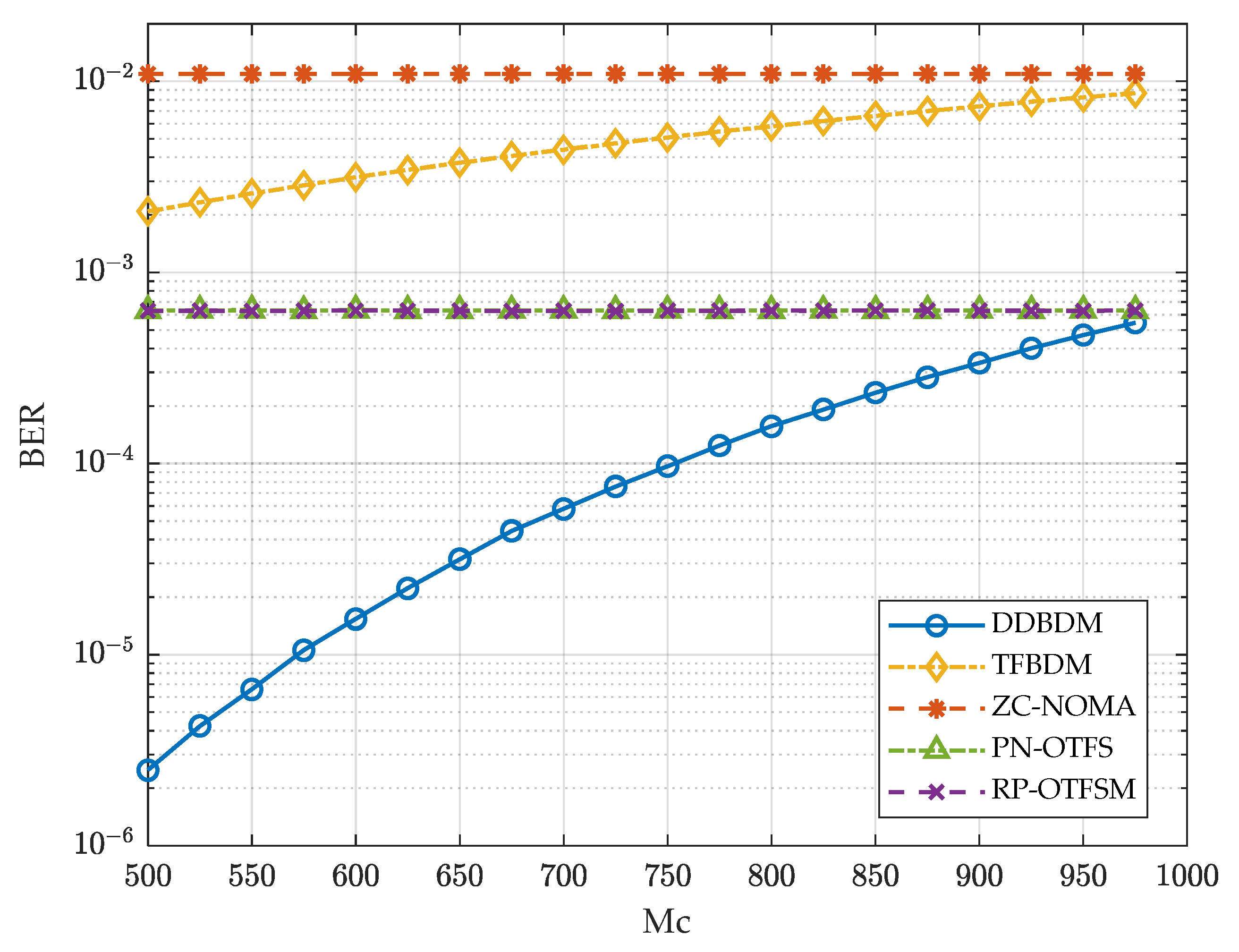
Figure 12 shows the BER curves varying with different numbers of communication subcarriers
Mc, where SNR = 10 dB and CNPR = 20 dB. It can be seen that the BER performance of DDBDM and TFBDM deteriorates as the bandwidth of the communication signal increases. This is because an increase in the noise bandwidth leads to a decrease in the effective SNR defined in (31), while the power of the communication signal remains constant. However, DDBDM still has the lowest BER compared to all other schemes. Moreover, the BER performance of PN-OTFS is almost the same as that of RP-OTFSM in this case, since the former allocates little power to the navigational message, and has little effect on the communication constellation diagram.
Finally, we summarize the performance of DDBDM signals under different CNPR and bandwidth (subcarriers) conditions. The primary function of LEO constellations is to provide broadband communication services, which typically means that the power and bandwidth allocated for navigation are less than those for communication. To ensure communication capacity when allocating bandwidth, it is necessary to allocate most subcarriers to communication signals. Based on the above results, it is appropriate to allocate 200 and 800 subcarriers for navigation and communication signals, respectively. In contrast to ZC-NOMA and PN-OTFS, we can allocate more power to the navigation signals of DDBDM to further improve the navigation performance, as the BER performance of DDBDM does not significantly degrade with a decrease in CNPR. Therefore, DDBDM not only achieves the lowest BER in broadband communication, but also provides fast and reliable augmentation information for PNT applications.
5.4. Prototype Implementation
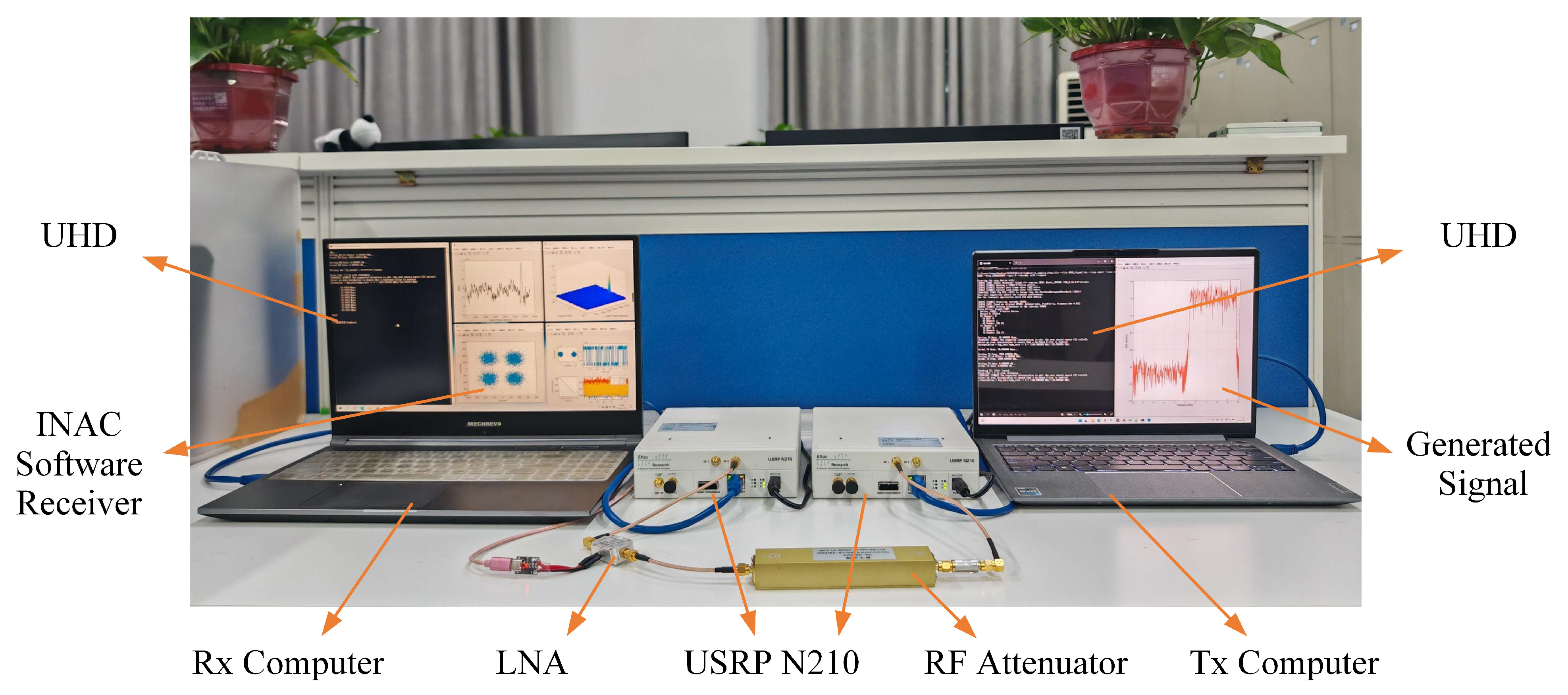
The comparison of ranging accuracy and data transmission reliability has been simulated in the previous subsections, and here, we focus on the validation of the feasibility of the proposed navigation receiver architecture in a practical system. We implement a prototype of the INAC system for DDBDM based on the SDR, and develop a software receiver utilizing the architecture proposed in
Section 4. The hardware system based on the SDR is shown in
Figure 13. The system includes two universal software radio peripherals (USRPs), transmitting and receiving terminals (Tx and Rx computers), a radio frequency (RF) attenuator, and a low-noise amplifier (LNA). The transmitting terminal generates the DDBDM discrete-time baseband signal file. The USRP hardware driver (UHD) program transmits the signal to the USRP via a network cable, and conducts digital-to-analog conversion. Another USRP down-converts and samples the analog signal, which passes through an RF attenuator and LNA. Subsequently, the UHD transmits the signal to the receiving terminal and saves it as a signal file. Finally, the software receiver processes the signal file to verify the feasibility of using DDBDM for navigation. The RF attenuator and LNA in the RF link jointly form an AWGN channel, where the RF attenuator can be adjusted to obtain the desired SNR. The effects of the high-mobility channel (maximum Doppler shift and Doppler rate of 0.91 ppm and 0.09 ppm/s, respectively) are considered in the INAC signal generation. As the navigation receiver processes LOS signals, it is justified for the validation of the navigation function in this channel.
The Ka-band exceeds the carrier frequency of most commercial SDRs, and the RF is reduced from 20 GHz to 2 GHz. The maximum Doppler shift and Doppler rate are still set to 0.91 ppm and 0.09 ppm/s, respectively [
54]. The master clock rate of USRP N210 is 100 MHz, and the sampling rate supported is limited to dividing the master clock rate by an integer factor. Therefore, the sampling rate of the transmitted signal is set to
fs = 20 MHz, the subcarrier spacing is Δ
f =100 kHz, and the numbers of total subcarriers, navigation subcarriers, and zero-padding subcarriers are
M = 188,
Mn = 88, and
Mp = 12, respectively. The sampling frequency for the navigation signal receiver is set to 10 MHz, and the RF center frequency should be offset by half of the navigation signal bandwidth, i.e., 1.995 GHz, based on 2 GHz. The SNR is 5 dB, and the CNPR is 23 dB, so the
C/
N0 of the navigation signal is 55 dB∙Hz. The coherent integration time
Tcoh = 0.16 ms (a signal frame duration), the noncoherent integration time is 1.6 ms, and the Doppler frequency search step of the PCS method is set to 6.25 kHz. The equivalent noise bandwidth of DLL is 0.2 Hz, the early–late spacing of the correlator is 0.5 chip, the PLL bandwidth is 60 Hz, and the other parameters are consistent with
Table 2.
Figure 14 shows the acquisition result of the DDBDM signal. The code phase (delay) is at the 2863rd sample. The peak of the correlation values is located at −12.5 kHz and the fine Doppler frequency is calculated as −12.6 kHz. This result is used to initialize the tracking loop.
Figure 15 shows the corresponding tracking results. The navigation message demodulation constellation and message bits are located on the top-left and top-right of the panel, respectively. The result indicates that even if the transmitted navigation message is spread by the PRN code mapping in the DD domain, the UE still measures the pseudo-range and demodulates the navigation message in the time domain. The bottom-left of the panel shows the Doppler frequency output by the PLL through the loop filter, which is consistent with the dynamic of 1.8 kHz/s (0.09 ppm/s × 20 GHz). The bottom-right of the panel shows the magnitude of the correlation function output from the DLL. The magnitude of the prompt branch is the highest, so the code tracking is successful. This indicates that the proposed receiver architecture is capable of independently receiving the DDBDM navigation signals and outputting accurate measurements of delay and frequency.
The experimental results verify the feasibility of the proposed waveform and navigation receiver architecture, indicating that DDBDM has the advantages of flexible reception and a low processing bandwidth. Furthermore, since the rectangular pulse in the TF domain is difficult to satisfy the bi-orthogonal robust property in practical applications [
30], an interesting direction in the future is to design INAC waveforms directly based on the DD plane orthogonal pulse to improve their performance in practical systems, instead of converting them to the TF domain.


