Review

Overview of Radar Jamming Waveform Design

College of Electronic Science and Technology, National University of Defense Technology, Changsha 410073, China
*
Author to whom correspondence should be addressed.
Remote Sens. 2025, 17(7), 1218; https://doi.org/10.3390/rs17071218
Submission received: 31 January 2025 / Revised: 25 March 2025 / Accepted: 27 March 2025 / Published: 29 March 2025

Abstract

:
Radar jamming waveform design is a vital part of radar jamming. Over seven to eight decades of evolution, the field has transitioned from noise signal design to coherent jamming signal design, resulting in a multitude of complex jamming styles capable of achieving deceptive jamming, suppressive jamming, and smart noise jamming, which combines both deception and suppression. For the first time, this article establishes a general formula for unifying jamming waveform design. Building upon this foundation, we systematically categorize jamming techniques, and provide an in-depth summary of the corresponding principles and conduct comparative analysis of their effectiveness against different targets. Finally, we look forward in terms of future research directions in jamming waveform design, including quantifiable jamming effect evaluation indicators, combined jamming styles, and intelligent jamming waveform generation methods to address the continuous advancement of radar technology and the complexity and variability of the electromagnetic environment. In order to fill the gap in the literature by summarizing the current state of the field and highlighting key challenges and opportunities, this review provides a comprehensive overview of radar jamming waveform design, categorizes and compares different jamming techniques, and identifies future research directions.

1. Introduction

To fully safeguard information security in regard to vital areas and prevent important targets from being detected by radar, radar jamming has become a crucial means to curb illegal radar detection. Radar jamming refers to electronic jamming measures that use radar jamming equipment or materials to radiate, scatter, or absorb electromagnetic energy, disrupting or weakening the radar’s ability to detect and track targets [1]. The effectiveness of radar jamming is mainly achieved through the selection of the jamming timing, the allocation of jamming resources, decision making in terms of jamming styles, and the design of jamming waveforms. Among these, the design of jamming waveforms, which involves highly technical content, flexibility, and interconnections with other aspects, is the core of radar jamming and occupies an important position in the radar jamming process. Through specific waveform design, effective jamming of radar systems can be achieved, reducing their detection and tracking capabilities. This involves multiple fields, such as signal processing technology and waveform optimization theory, requiring a comprehensive consideration of the working principles of radar systems, the characteristics of jamming signals, and the electromagnetic environment.
In the 1940s and 1950s, the development of radar jamming waveform design was in its early stages. During this period, radar systems were relatively simple, with fixed working frequency bands and weak anti-jamming capabilities. Barrage noise jamming could achieve good jamming effects.
In the 1960s and 1970s, with the advancement of radar technology, radar systems began to adopt various anti-jamming techniques, such as frequency agility and pulse width agility. Jamming waveform design also became more complex, with the emergence of noise jamming techniques with higher power and wider frequency coverage, as well as various deceptive jamming methods and comb spectrum jamming techniques for frequency-agile radars [2].
From the late twentieth century to the present, in response to more complex radar systems, jamming waveform design has become more refined and diversified, with increased attention being paid to parameters such as the phase and jamming duration in regard to waveforms. After the concept of cognitive radar [3] was proposed, related counter theories also emerged. During the design process, machine learning algorithms are applied to enhance the intelligence and adaptability system.
This paper summarizes the current research status of radar jamming waveforms from the perspectives of jamming effects, jamming targets, and stages of jamming action, and proposes a general formula for jamming waveforms.
The primary objective of this review is to provide a comprehensive overview of radar jamming waveform design, categorize and compare different jamming techniques, and identify future research directions. This review aims to fill the gap in the literature by summarizing the current state of the field and highlighting key challenges and opportunities.

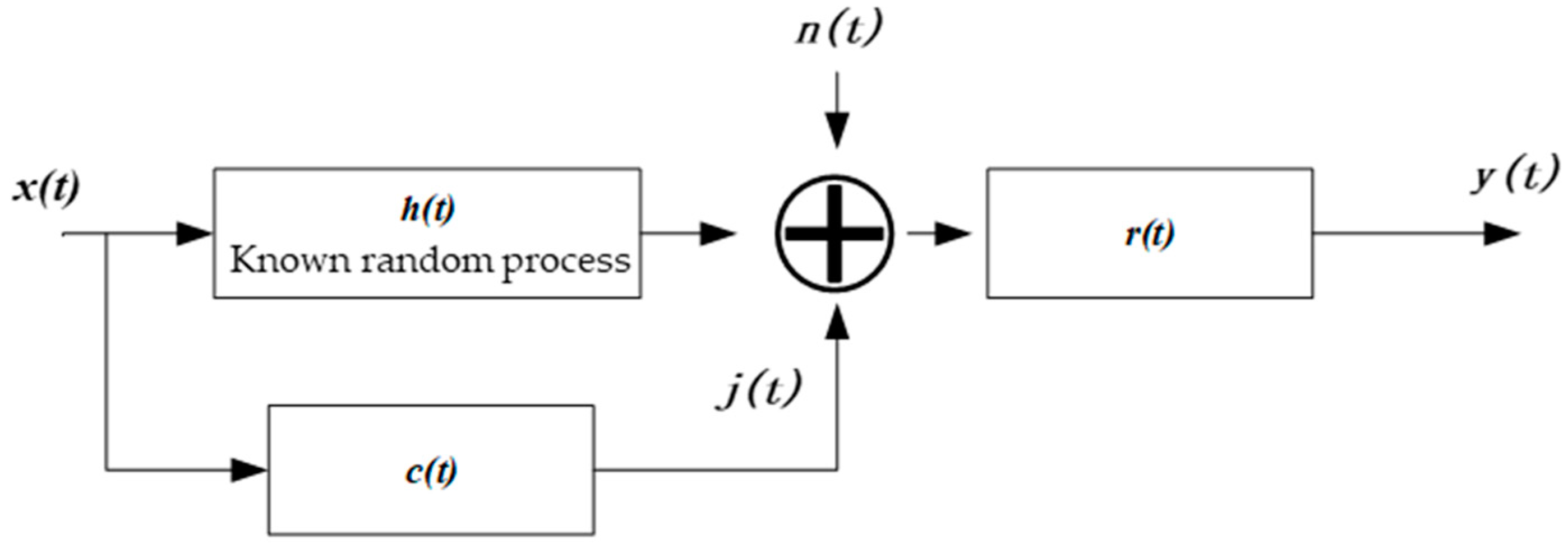
2. General Formula for Jamming

According to the current research status, the general formula for jamming waveform design can be obtained by summarizing various factors in the design of jamming waveforms:
s j ( t , τ ) = i A ( t ) × { G i ( t , τ ) × [ a 1 × s ( t , τ ) × n p r o ( t , τ ) + a 2 × s ( t , τ ) n c o n v ( t , τ )     + a 3 × s ( t , τ ) + a 4 × n n o i s e ] × e x p [ 2 j π g i ( t , τ ) ] } δ ( f i ( t , τ ) ) s . t . a i a 1 , a 2 , a 3 , a 4 , a i N i = 1 4 a i = 1
In the formula, represents the summation operation; i indicates the objects that are to be summed up; × denotes multiplication; and signifies convolution; A ( t ) represents amplitude modulation; G i ( t , τ ) is a rectangular pulse with an amplitude of 1; s ( t , τ ) is the target radar signal; n p r o ( t , τ ) is the noise waveforms used for product modulation; n c o n v ( t , τ ) is the noise waveforms used for convolution modulation; n n o i s e represents the noise jamming signal; e x p [ 2 j π g i ( t , τ ) ] denotes frequency modulation; g i ( t , τ ) is the frequency modulation factor; and δ ( f i ( t , τ ) ) indicates time delay modulation, with f i ( t , τ ) being the time delay factor. Because there are only a few cases in current waveform design where the original signal, modulated signal, and pure noise are mixed together, in the equation, only one variable in a i a 1 , a 2 , a 3 , a 4 has a value of 1, with the rest being 0. Please refer to Table 1 for specific combinations, where ‘/’ indicates that no relevant modulation has been performed.
This formula is proposed to lay the groundwork for the introduction of various waveforms in the subsequent sections of this review. It aims to enable us to comprehend diverse jamming styles from a mathematical perspective and to inspire innovative ideas for the design of jamming waveforms.

3. Classification Based on Jamming Effects

In Section 2, the principle of modulating jamming waveforms has been introduced, and this section introduces the classification of jamming waveforms based on the effect of jamming.
Radar jamming can be classified into two types, based on its effects: barrage jamming and deceptive jamming. Barrage jamming refers to the use of noise or noise-like jamming signals to overwhelm the target echo, preventing the receiver from extracting information from it. Deceptive jamming, on the other hand, involves using jamming signals to confuse the real target echo, causing the radar to obtain incorrect information.

3.1. Barrage Jamming

Barrage jamming can be further divided into broadband blocking jamming and directed jamming. Blocking jamming has a wide frequency spectrum, capable of covering a large range of frequencies. However, it has a low power utilization rate. Due to hardware design limitations, the jamming energy that can be allocated to each frequency point is relatively low, and its principle is relatively simple, which will not be elaborated in this paper. Directed jamming, on the other hand, uses narrowband noise signals to accurately target and interfere with specific frequency bands. Compared to broadband blocking jamming, it has a higher energy utilization rate.

3.1.1. Single-Band Jamming

For single-frequency bands, traditional directed jamming primarily involves modulating high-power noise signals. When these signals enter the radar electronic system, they cause the radar receiver to saturate. This results in the radar losing its ability to detect targets, thereby achieving the jamming objective. From a frequency domain perspective, the noise involved in this type of jamming is mainly narrowband random signals. By modulating the narrowband noise onto the center frequency of the radar signal, it ensures that the noise can pass through the filter and enter the receiver. This method utilizes limited effective information from the radar and is simple to implement, but it is too crude, so jamming effectiveness is not fully realized.
Ref. [4] modeled the jamming process based on whether the characteristics of the protected target are known, as shown in Figure 1. Here, h(t) represents the target scattering characteristics, x(t) is the received radar signal, c(t) is the jammer channel, n(t) is the noise in the environment, r(t) represents the receiver channel, and y(t) is the signal received by the receiver. Jamming reduces the signal-to-jamming-plus-noise ratio (SJNR), thereby weakening the radar’s target detection capability; it also reduces the mutual information (MI) between the echo and the impulse response of the target, weakening the radar’s ability to estimate target parameters [5,6]. The water-filling method [7] can be used to calculate the optimal colored noise power spectrum. Refs. [8,9] applies KL divergence to radar waveform design, which can be used to evaluate the similarity of echoes with and without jamming.
This method can fully utilize the radar signal, the scattering characteristics of the protected target, and environmental information to achieve precise and efficient directed colored noise jamming. However, during the power spectrum calculation process, the phase information is ignored, resulting in weak phase coherence between the generated jamming and the radar waveform. Consequently, the jamming effect is greatly weakened after matched filtering.

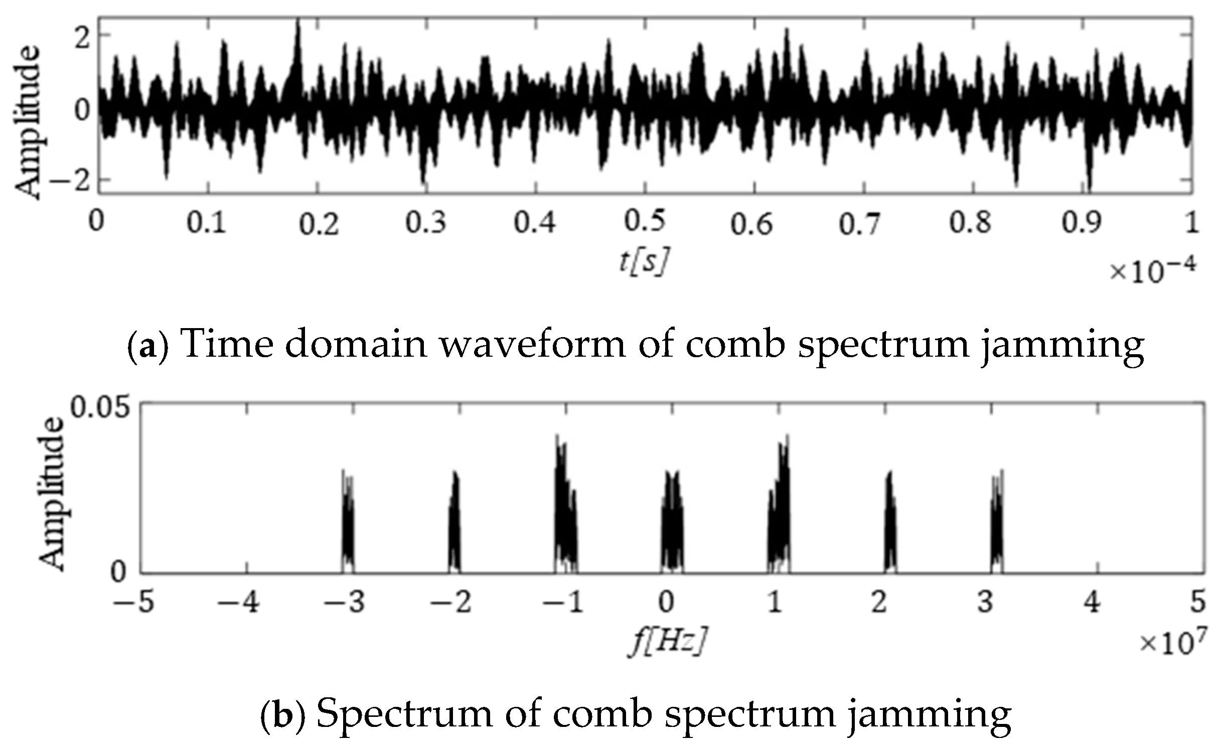
3.1.2. Multi-Band Jamming

With the development of frequency agility technology, it is difficult to effectively interfere with signals at multiple frequency points using traditional narrowband directed jamming in terms of barrage jamming. On the other hand, barrage jamming, due to its wide bandwidth, has a more dispersed energy distribution across different frequencies. Therefore, in situations where there is limited jamming energy, its effectiveness is limited. In comparison, comb spectrum jamming can target the working frequency points of frequency-agile radars, thus solving the aforementioned problems [10,11].
Comb spectrum jamming can frequency shift the jamming signal to act on multiple frequency points simultaneously [12], and the basic formula is:
j ( t ) = k = 1 K a k e j ( 2 π f k t ) N ( t )
In the formula, K represents the total number of frequency shifts, a k denotes the amplitude gain of the k -th frequency shift, f k represents the size of the frequency shift, and N t is the jamming signal. Figure 2 shows a reproduction of the simulation of comb spectrum jamming presented in ref. [12].
In 2014, Shen and others proposed a broadband SAR subband pulse modulation comb spectrum jamming technique [13], utilizing the partial coherence of subband modulated pulses of broadband SAR radar signals and the frequency shifting characteristics of comb spectrum jamming signals. Since subband modulated pulses can achieve partial processing gain after matched filtering, the comb spectrum modulation of subband pulse signals is equivalent to copying and shifting the subband pulses in the frequency domain, increasing the density of the jamming signal and, thereby, improving the jamming effect.
In 2020, An and others addressed the issue of the high peak-to-average power ratio (PAPR) in comb spectrum jamming. They analyzed the relationship between the PAPR of comb spectrum signals and the clipping rate and number of jamming signals [14]. At the same time, they proposed a PAPR improvement method based on neural network learning. This method uses neural networks to adaptively select an appropriate clipping rate for the comb spectrum jamming signal, effectively improving the PAPR, while maintaining the original spectral characteristics of the signal.
Comb spectrum jamming signals are the result of superimposing multiple frequency shifts of the baseband signal. Their frequency characteristics allow them to precisely interfere with multiple frequency points simultaneously, effectively countering radar systems with frequency agility. They are highly flexible and can adjust the frequency points and intensity of the jamming as needed. However, this type of jamming is relatively dispersed in terms of frequency points, which means that the jamming energy is somewhat dispersed. The effectiveness of the jamming also largely depends on the choice of the baseband signal. If the reconnaissance is insufficient and the baseband signal is poorly chosen, the jamming effect will be significantly compromised. When signals from multiple frequency points are superimposed, controlling the PAPR is challenging, which is the biggest obstacle faced by this jamming technique in practical engineering applications.

3.2. Deceptive Jamming

The development of jamming technology is deeply influenced by the advancement of reconnaissance technology. In the early stages, radar systems were relatively simple, and the information obtained by reconnaissance was limited. Jamming specific frequency points was sufficient to achieve good results. However, with the development of pulse compression processing technology, it has become increasingly difficult for non-coherent jamming signals to achieve their objectives through radar signal processing. In this context, the importance of coherent technology has become more prominent, which has also driven the development of digital radio frequency memory (DRFM) [15] technology.
In engineering, the process of DRFM generally involves down-converting the intercepted signal, digitizing it through the use of an Analog-to-Digital Converter (ADC), and storing it on a high-speed memory, typically a Random Access Memory (RAM). Then, according to the requirements, the stored signal is specially modulated, and through the use of a Digital-to-Analog Converter (DAC) and upconversion by a mixer, it is restored to a radio frequency signal and transmitted into space (as shown in Figure 3).

3.2.1. Full-Pulse Repetition Jamming

At the beginning of this century, the design methods for jamming waveforms based on DRFM technology were primarily focused on range and velocity false target deception jamming [16,17]. The idea is to use DRFM to intercept and store a pulse, and then delay and retransmit the pulse to achieve deception.
In ref. [18], a DRFM jamming method for full-pulse storage and retransmission against linear frequency modulated (LFM) pulse compression radars is introduced. Mathematical models for stationary and moving false targets are constructed, and their range image jamming effects are verified through simulations. Ref. [19] analyzes the basic principle of range false target deception jamming for fire control radars and establishes an evaluation index for the jamming effects. Combined with tactical data, it analyzes the jamming effects of a range of false targets. However, when generating multiple false targets in the above literature, each target must be modulated individually, and the signal PAPR is uncontrollable when multiple false targets are superimposed, which can easily cause signal distortion during engineering implementations.
Ref. [20] proposes a speed domain multi-false-target deception jamming implementation scheme based on a digital radio frequency memory, discussing the modulation method of jamming information. To address the high PAPR of the jamming signal, a phase-shifting method was used and achieved good results.
Ref. [21] systematically introduces the working mechanisms and mathematical models of various false target jamming methods and simulates their effects on MIMO radars. Ref. [22] introduces the basic principles of generating velocity range false targets.
In situations where there is prior knowledge of the location and RF radiation parameters of networked radar stations, ref. [23] proposes a solution based on the concept of a “homologous test” and a certain spatial resolution of networked radar.
However, all the false target deception jamming waveforms mentioned above must be generated after successfully intercepting one or more complete pulses and then modulating them. This means that the jamming signal must lag behind the radar signal by at least one pulse width, resulting in low real-time performance of the jamming.

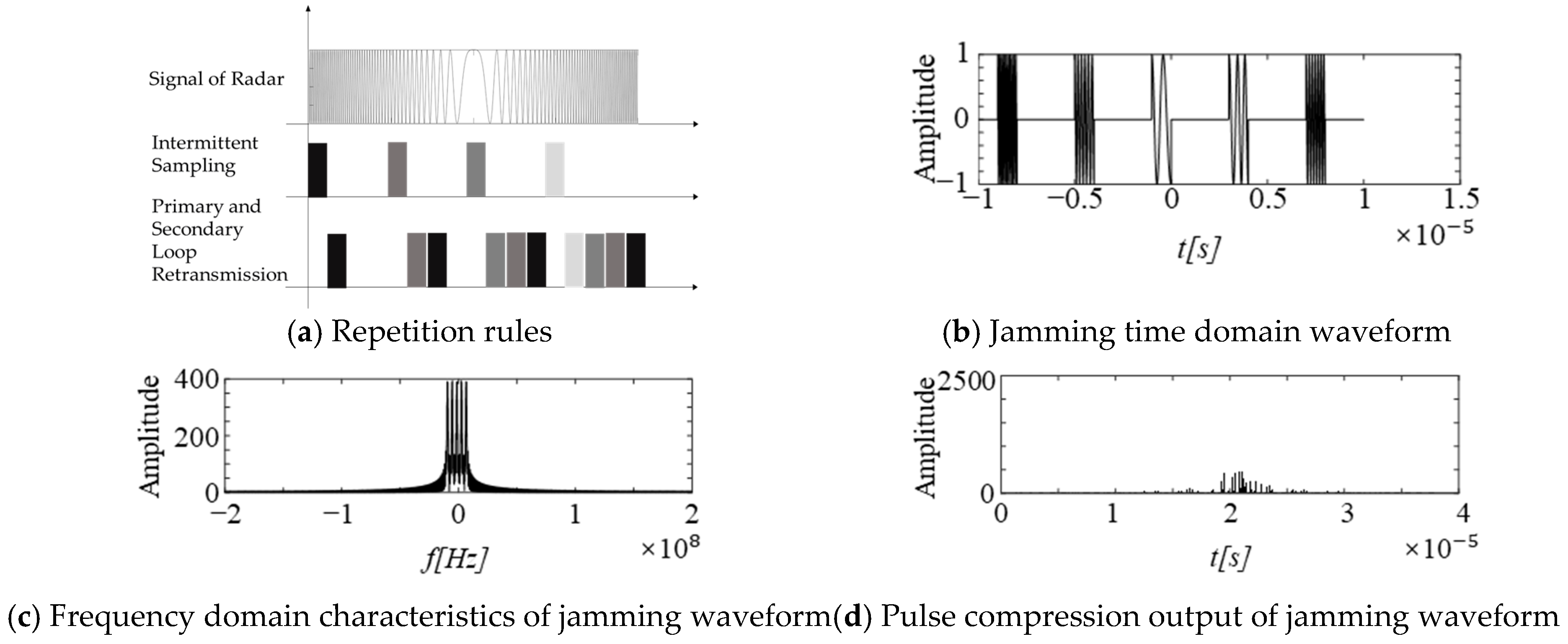
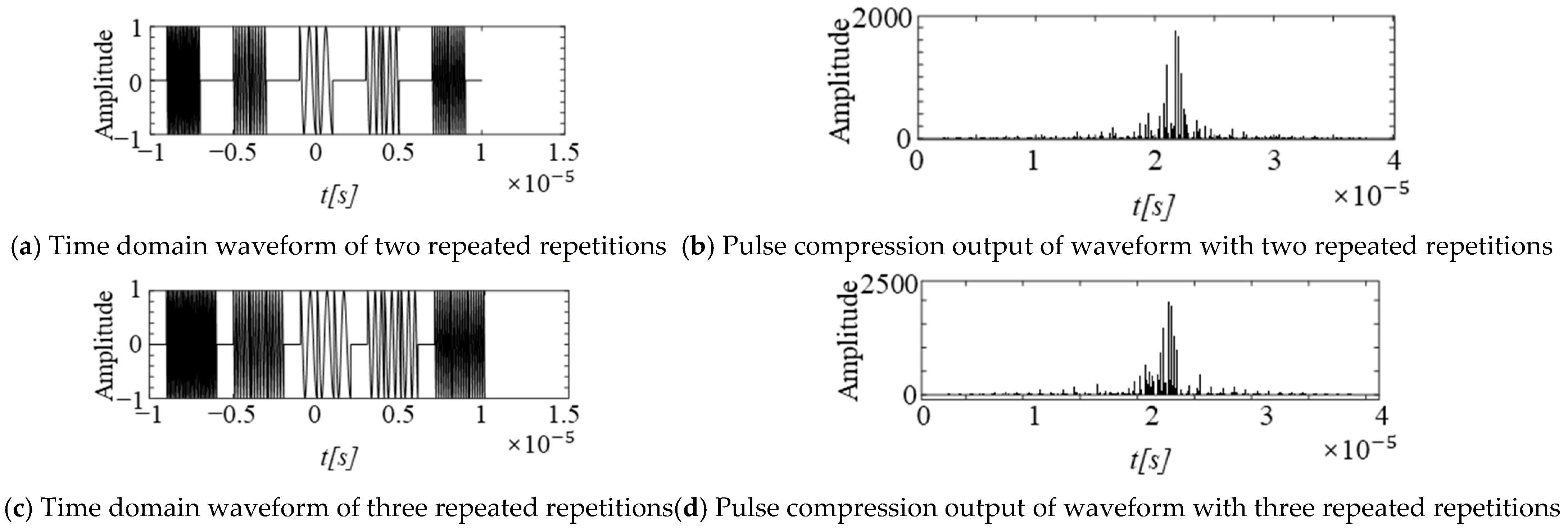
3.2.2. Intermittent Sampling and Repetition Jamming

Intermittent sampling and repetition jamming was formally proposed by Wang’s team from the National University of Defense Technology in 2006 [24]. The original intention was to address practical engineering issues, such as low isolation between transmitting and receiving antennas on missile-borne jammers. For LFM signals with a large time-bandwidth product, they adopted a method of receiving and retransmitting in segments, which can be seen as using the different times for reconnaissance and jamming to gain isolation between the transmitting and receiving antennas, sacrificing some coherence in terms of the jamming signal for stronger real-time performance.
Notably, the jamming signal produced by this method not only has good coherence and real-time performance, but also, after matched filtering, can generate a series of regularly distributed false targets with the   sinc function as the envelope. This has attracted widespread attention within the academic community [25]. The following year, in ref. [26], the team conducted an in-depth analysis and discussion of the mathematical principles of this type of jamming and pointed out the cause of the false targets.
j ( t ) = r e c t ( t τ / 2 τ ) n = + δ ( t n T s )
In this context, r e c t t is the rectangular pulse, τ is the duration of a single sampling period, T s is the sampling and retransmission period   ( τ > T s / 2 ) , and is the convolution operator. In the frequency domain:
J ( f ) = n = + τ f s sinc ( n f s π ) exp ( j n τ f s π ) δ ( f n f s )
When the received signal is s(t), let its spectrum be S(f). The spectrum of the output jamming signal is defined as:
J s ( f ) = n = + τ f s sinc ( n τ f s π ) exp ( j n τ f s π ) S ( f n f s )
In this context, f s = 1 T s . From n = + sinc ( n τ f s π ) exp ( j n τ f s π ) , it can be deduced that the result of the matched filtering after jamming is the weighted periodic extension of multiple sinc functions.
The intermittent sampling and repetition jamming signal initially employed a method of “sampling a segment and then retransmitting that segment” to generate the signal.
From Figure 4, which is a reproduction of the simulation, we can see that after pulse compression processing, this type of jamming signal can form a series of false targets that are uniformly distributed in time. In (a), different color blocks represent different waveform segments that are sampled or forwarded. The outermost layer of the false targets is modulated by the sinc function, and the main lobe width of the sinc function is twice that of the sampling and retransmission period. The false targets in the pulse compression output of this type of jamming signal are uniformly and sparsely distributed in the time domain, with rapid amplitude decay and strong regularity in their changes, making them easily eliminated by anti-jamming techniques during the jamming process. Therefore, the sampling and retransmission rules can be changed to improve the jamming effect [27].
As a result, researchers have adopted methods of intermittent sampling and repeated retransmission, as well as sequential cyclic retransmission, in order to address the issues of rapid false target decay and sparse distribution.
From Figure 5, which is a reproduction of the simulation, the pulse compression output result is improved, the number of false targets increases, with multiple similar false targets emerging near the original single false target. The more times the signal is retransmitted, the more false targets are generated, which slows down the rate of amplitude decay. However, the false targets formed by this type of jamming are still distributed at equal intervals, and the envelope is still approximately the sinc function.
As shown in Figure 6, which is a reproduction of the simulation, the false targets generated by this jamming method are also weighted extensions of the sinc function. The intervals between the false targets remain fixed, but the regularity of the weights becomes less apparent. Since the false targets appear at fixed intervals, they are easily filtered out using anti-jamming techniques. Therefore, researchers later began to focus on more complex design methods, such as non-uniform sampling and phase modulation during retransmission, which ultimately led to the development of smart jamming effects from intermittent sampling and retransmission jamming (this will be discussed in Section 3.3).

3.3. Smart Noise Jamming

Smart noise jamming combines the advantages of noise suppression jamming and false target deception jamming [28]. Through the use of special modulation methods, jamming waveforms with a certain degree of coherence are generated, causing the radar signal processing output to exhibit both false target deception effects and noise masking effects. Therefore, some studies in the literature also refer to it as dense false target jamming [29]. The origin of the proposal is difficult to trace, but it represents a breakthrough in terms of the traditional classification of jamming types.
There are many ways to generate this type of jamming waveform, primarily relying on the modulation of pulse intermediate frequency data intercepted by DRFM to achieve the desired jamming effects. These methods can be categorized based on the completeness of the pulse: methods for generating jamming signals by modulating complete pulses and methods for generating jamming signals by modulating pulse segments.

3.3.1. Jamming by Modulating Complete Pulses

Ref. [30] presents methods for designing jamming waveforms using complete pulses for modulation, including pulse overlapping, frequency domain modulation, time domain modulation, and simultaneous frequency and time domain modulation.
Ref. [31] simulates the pulse delay overlapping method, and ref. [32] simulates the pulse frequency shift superposition method. Both methods yield good jamming effects in simulations, but controlling the PAPR remains challenging in engineering implementations.
Refs. [17,33,34] all use noise templates to perform product modulation on pulse signals to obtain jamming waveforms, which can form controllable range smart noise jamming effects in regard to ranging and imaging.
Refs. [16,35,36] use noise waveforms to perform convolution modulation on pulse signals to obtain jamming waveforms. The resulting jamming effects can impact multiple radar functions, including ranging, velocity measurement, and imaging. However, compared to product modulation, convolution modulation significantly increases the computational load.
Both product and convolution modulation can reduce the PAPR in the time domain waveform to some extent. However, like the pulse overlapping method, they require the interception of a complete pulse before the corresponding jamming signal can be generated, resulting in a noticeable lag in jamming.

3.3.2. Jamming by Modulating Pulse Segments

In regard to an LFM pulse, any segment extracted from it can be considered as a partially coherent LFM pulse with the original signal. After radar matched-filtering processing, it can also achieve a processing gain [37]. Therefore, by quickly extracting segments of the radar signal and performing corresponding modulation, the effect of smart noise jamming can be presented in the matched-filtering output [38]. Refs. [33] and [31], respectively, use equidistant sampling and pulse sampling methods to generate smart noise jamming signals, but the distribution of the generated false targets is too regular. If the pulse segments are overlapped, there are issues with controlling the PAPR and achieving complete isolation of the transmitting and receiving antennas in the duplexer.
In recent years, many papers have achieved the effect of smart noise jamming by specially processing intermittent sampling and retransmission jamming [39]. This method effectively avoids the above two problems.
In refs. [40,41,42], Chen’s team, based on intermittent sampling and repeated retransmission jamming, and considering the non-cooperative nature of reconnaissance, modeled the radar pulse width as an unknown length. They first studied the conditions according to which the pulse width is determined, with a fixed sampling period, T s .
T s = ( 1 + n i ) τ i
In this context, n i represents the number of retransmissions, and τ i is the sampling duration. When τ i is determined, n i is also correspondingly determined. The paper mainly studies the impact of the sampling duration on the jamming effect and optimizes the jamming effect segment by segment, using the “cutting assumption method”, ultimately forming a non-uniformly sampled intermittent sampling and retransmission jamming waveform. Ref. [43] also involves similar research.
As shown in Figure 7, which is a reproduction of the simulation, this is a simulation of non-uniform intermittent sampling and retransmission jamming signals for an LFM pulse, with a pulse width of 20 μs and a bandwidth of 10 MHz. First, a sampling and retransmission period of 2 μs is used, denoted as T s , which allows the signal to be divided into 10 sub-pulses. Then, the number of retransmissions for each sub-pulse is selected, denoted as n i [ 1 , 9 ] , which determines the sampling time length as T s 1 + n i . The objective function is:
d = E [ y ( t ) ] σ [ y ( t ) ]
where y ( t ) represents the pulse compression output, E [ · ] denotes the mean operation, and σ [ · ] represents the standard deviation operation. By adjusting the value of n i , the pulse compression output of the jamming waveform is optimized to make it more suppressive. In terms of optimization algorithms, group intelligence algorithms, such as genetic algorithms and ant colony algorithms, are commonly used, and Q-learning algorithms can also be employed.
Following a similar approach, Zhang used the particle swarm optimization algorithm. By varying the phase modulation of the intermittent sampling and retransmission jamming signal, he sought the optimal jamming waveform to jam with phase-coded signals [44]. The objective function is:
d = ω 1 E ( | y ( t ) | ) / max ( y ( t ) ) ω 2 σ ( | y ( t ) | / max ( y ( t ) ) )
This function is very similar to Equation (6), both aiming to increase the ratio of the mean to the standard deviation of the pulse compression output, so that the pulse compression output can be evenly distributed in the time domain. This reduces the regularity of the false targets and enhances its suppressive effect.
Furthermore, in refs. [45,46,47], researchers have also applied intermittent sampling and retransmission jamming to the study of jamming with phase-coded radar signals. By designing the jamming waveform, it is possible to produce a smart noise jamming effect wherein advanced and delayed false targets overlap.
As mentioned above, intermittent sampling and retransmission jamming involves truncating the original pulse, and the resulting jamming signal retains a significant amount of matched-filtering gain. For radars that use pulse compression processing, the jamming effect is significantly more prominent than for other types of jamming. However, the regularity of the waveform and the lag of the main false target make it susceptible to filtering. To address the regularity issue of the jamming waveform, researchers mainly focus on changing the retransmission rules to make the pulse compression output more complex and obscure the regularity. For the lag issue of the main false target, researchers have provided two approaches: one is to apply phase modulation to the intermittent sampling and retransmission jamming signal for phase-coded signals, enabling it to produce advanced pulse compression output with false targets; the other is to adjust the sampling duration and the number of retransmissions to optimize the pulse compression output into a more evenly distributed dense array of false targets. In this case, the real target echo is submerged in the jamming signal and cannot be distinguished from the false target and the real echo signal based on the lag of the main false target, achieving an effect of deception combined with suppression. Waveform design offers many parameters for adjustment, allowing for diverse jamming effects and demonstrating strong flexibility.

3.4. Comparative Analysis

The development of jamming waveform design has reached a stage where traditional classifications of suppression or deception effects no longer cover all types of jamming effects. Smart noise should be considered as a separate category within waveform design classification.
Traditional suppression jamming primarily uses colored noise signals. It aims to achieve jamming by increasing the signal-to-noise ratio (SNR) to reduce the probability of target echo detection. The main characteristics are simplicity and ease of modulation, and it is capable of overwhelming echoes over a wide range, but it is non-coherent. Before the introduction of intermittent sampling and retransmission jamming, deception jamming involved capturing complete pulses, modulating them to generate false targets or strings of false targets, or forwarding larger amplitude echoes to lure the tracking gate. Its characteristics include high realism of the false targets and signal coherence, but it requires accurate reconnaissance parameters, has a large computational load, difficulties in regard to the isolation of transmitter and receiver antennas, low real-time performance, and difficulty in suppressing the PAPR in multiple false target scenarios. Intermittent sampling and retransmission jamming, while solving the isolation problem related to transmitter and receiver antennas, improving real-time performance, and making the PAPR controllable, produces regularly distributed multiple false targets that are easily recognizable. Smart noise jamming combines suppression and deception, using coherent jamming signals to affect target detection in the corresponding area. A specific comparison of jamming technique performance is shown in Table 2.
Currently, there is no unified evaluation criterion for measuring the effects of various jamming waveforms. Barrage jamming using noise signals primarily relies on the SJNR as the criterion for evaluating jamming effectiveness [4]. The objective function is:
min S c c ( f ) S J N R S c c ( f ) s . t . S J N R = H ( f ) X ( f ) 2 X ( f ) 2 S c c ( f ) + S n n ( f ) d f B W S c c ( f ) d f P
Here, X ( f ) and H ( f ) are the Fourier transforms of the radar signal and the target impulse response, respectively; S c c ( f ) is the characteristic of the jammer; and S n n ( f ) is the power spectrum of the environmental additive noise.
For deceptive jamming using retransmitted radar signals (mainly including range and velocity false targets), the evaluation criteria for jamming effectiveness are primarily considered from a statistical perspective. For example, the probability of successful range deception is often used as an indicator:
P = N M
where P is the probability of successful deception, N is the number of successful deceptions, and M is the total number of deception attempts. A deception is considered effective if, within a deception cycle, the range error is greater than half the width of the tracking gate, or the time the tracking gate follows the target is less than half the deception cycle. The effectiveness of the deception is influenced by the SNR and the timing of the jamming, but these factors are not mathematically expressed in the probability formula.
Additionally, the maximum deception range can be used to characterize the effectiveness of range deception jamming. The maximum deception range is the maximum distance according to which the jammer can drag the radar tracking gate away from the real target. Generally, the farther the tracking gate can be dragged, the better.
R max = t 1 t 2 v ( t ) d t
where t 1 represents the start time of a jamming cycle, t 2 represents the end time of a jamming cycle, and v represents the deception velocity.
The evaluation of velocity deception jamming is also similar.
For the evaluation of multiple false target deception jamming, the approach is also statistical.
One aspect concerns the maximum number of false targets. That is, during the test, the multi-false-target jammer is operated to its maximum capacity to release as many false targets as possible, and the number of false targets tracked by the radar is recorded. After multiple tests, the average value is calculated. The more targets, the better the performance.
n max = 1 N i = 1 N n max i
where n max i represents the number of false targets in the i -th trial, and N represents the number of trials.
The second aspect is the false target jamming effectiveness ratio. If in the i -th trial, the total number of false targets released is N J i and the number of false targets tracked by the radar is N F i , then the false target jamming effectiveness ratio for that trial is given by:
K J i = N F i N J i
The radar false target jamming effectiveness ratio after multiple trials is given by:
K J = 1 N i = 1 N K J i
Thirdly, in tactical applications, the success rate of single-target penetration can also be used to characterize the effectiveness of jamming.
For the effectiveness of smart noise jamming, the optimization objective function has already been provided in Equation (7), using the ratio of the mean to the standard deviation of the pulse compression output to evaluate the jamming effect within a certain range in the range dimension. However, such an evaluation method has not been used for range–velocity or range–azimuth imaging results. The main method is still through visual observation of the output results, and conducting a qualitative comparative analysis. Essentially, it is about minimizing the SJNR or the target detection probability, P d .
arg min S J N R ( θ ) o r arg min P d ( θ )
where θ represents the set of adjustable parameters.
In summary, since the mechanisms and effects of various jamming types are different, it is not possible to provide a unified evaluation formula like the general formula for jamming waveforms. The current evaluation methods are mainly divided into three categories: First, during the testing phase, the functionality of the radar is assessed through the use of Monte Carlo experiments to determine whether the radar functions are achieved. Second, focusing on radar signal processing methods, the optimal jamming waveform design is derived using mathematical tools. Third, the output results with and without jamming are compared through visual observation.
These methods are not universal, and the effects of different types of jamming cannot be compared. This hinders researchers from optimizing the jamming waveform. This also hinders researchers from quantitatively evaluating the jamming effects of different jamming waveforms on different radars.

4. Classification Based on Jamming Targets

Radar is commonly used for ranging, speed measurement, and imaging. The emphasis of jamming varies for radars with different functions. This section takes typical pulse compression radar, pulse Doppler radar (PD radar), and SAR, as examples, to analyze the current interference waveform technologies for different radars.

4.1. Jamming Against Pulse Compression Radars

4.1.1. Principle of Pulse Compression Radars

Pulse compression radar is a type of radar system that transmits high-energy pulses with a long duration and then compresses the received echoes into short pulses, using a matched filter. This technique allows the radar to achieve a high resolution, while maintaining a long detection range.
The basic principle of pulse compression radar involves transmitting a long pulse with a wide bandwidth to ensure sufficient energy for long-range target detection. This pulse is typically modulated using a linear frequency modulation (LFM) technique, which introduces a frequency sweep across the pulse duration. When the pulse encounters a target, it reflects as an echo, which is also modulated in the same way. The received echo is then processed through a matched filter, designed to compress the long pulse into a short, high-amplitude pulse. This compression is achieved by correlating the received signal with the transmitted signal’s modulation pattern. The resulting narrow pulse corresponds to the target’s location, with its width inversely proportional to the transmitted signal’s bandwidth, thus achieving a high-range resolution. During this process, the noise and matched filters are not coherent, so they are suppressed. That is shown in Figure 8.

4.1.2. Jamming

For jamming against pulse compression radars, traditional noise jamming cannot achieve a processing gain, resulting in low effectiveness. Therefore, researchers have focused more on deceptive or smart jamming techniques. Many studies revolve around intermittent sampling and retransmission jamming, which has been discussed in previous sections regarding its process and advantages against pulse compression radars. Ref. [48] studies the generation of leading false target clusters, based on an intermittent reception and transmission jamming system, using frequency modulation and amplitude compensation of the intermittent sampling LFM signal. Ref. [49] proposes a jamming method based on segmenting and forwarding the entire radar pulse signal. Through reasonably segmenting and forwarding the complete radar pulse signal, it provides a formula for calculating the number of pulse segments when the false target amplitude is not lower than the true target, as well as the requirements for the forwarding sequence when the number of false targets is maximized. The literature also proposes an N-order spectral expansion–compression method, which can produce leading, trailing false target jamming, and suppression jamming.

4.2. Jamming Against PD Radars

4.2.1. Principle of PD Radars

PD radar is a new type of radar developed based on moving target indication (MTI) radar. This radar possesses the range resolution of pulse radar and the velocity resolution of continuous wave radar, offering stronger clutter suppression capabilities (as shown in Figure 9).

4.2.2. Jamming

Previously, the jamming against PD radars was primarily based on noise jamming [50,51]. This involved frequency measurement of the radar signal to guide the jammer to produce narrowband directed or broadband blocking jamming. For example, ref. [50] analyzed the signal characteristics of PD radars from the perspective of the frequency domain, studied the relationship between the bandwidth settings of the PD radar’s filter bank and the radar pulse repetition frequency, and combined the effects of noise frequency modulation jamming on phase detection receivers to provide a reasonable bandwidth for jamming PD radars. However, noise lacks the coherence characteristics of radar signals. Therefore, the jamming effect is poor.
Subsequently, jamming against PD radars entered the stage involving coherent jamming methods, which can still be mainly divided into deceptive jamming and smart jamming. Ref. [52] proposed methods for generating narrowband noise jamming and deceptive jamming using digital phase shifters and frequency synthesis devices, based on some basic jamming techniques. Ref. [52] studied the impact of smart noise jamming on the signal processing part of PD radars and quantitatively evaluated the jamming effects of four types of smart noise. Ref. [53] used different jamming methods based on the radar signal repetition frequency. In low repetition frequency conditions, wide pulse coverage jamming was used, superimposing a broadened coverage pulse with target Doppler characteristics on the target. Due to the action of the radar’s constant false alarm circuit, the detection threshold is increased to suppress the real target. In medium and high repetition frequency conditions, Doppler false echo jamming was used, with modulation producing multiple deceptive Doppler echoes, disrupting the PD radar’s target resolution. Ref. [54] compared the jamming effects of noise jamming, range multiple false target jamming, velocity multiple false target jamming, velocity–range two-dimensional multiple false target jamming, and intermittent sampling and retransmission jamming.

4.3. Jamming Against SAR

4.3.1. Principle of SAR
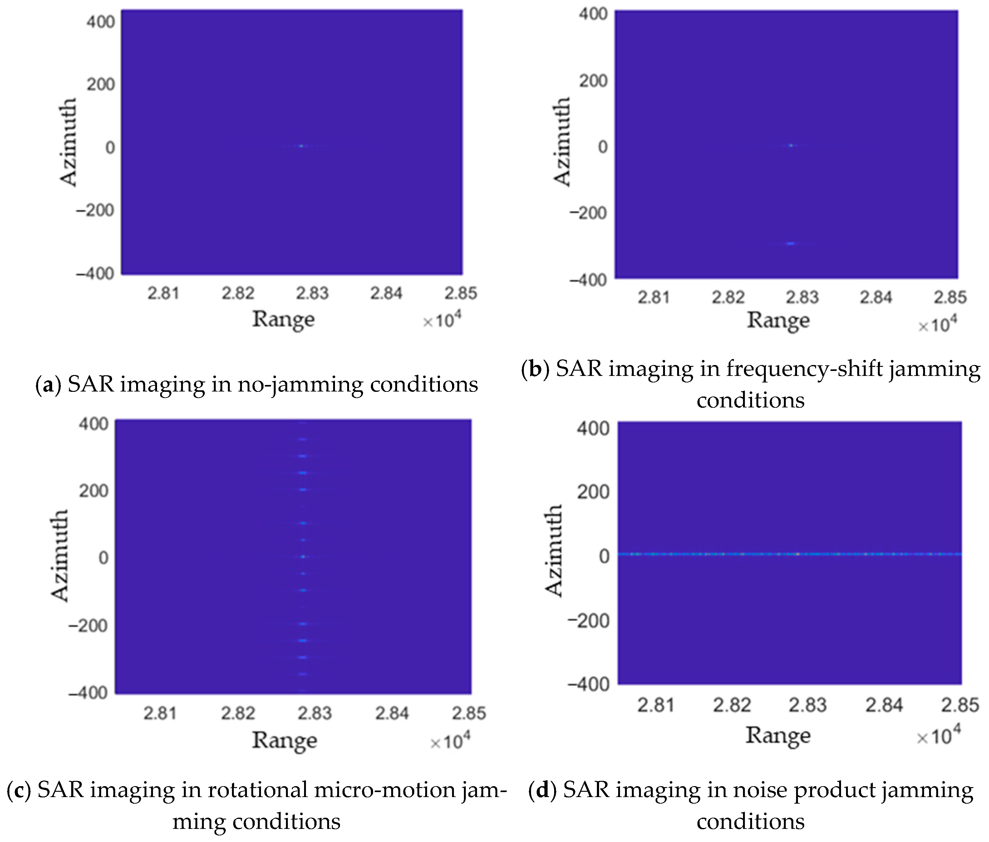
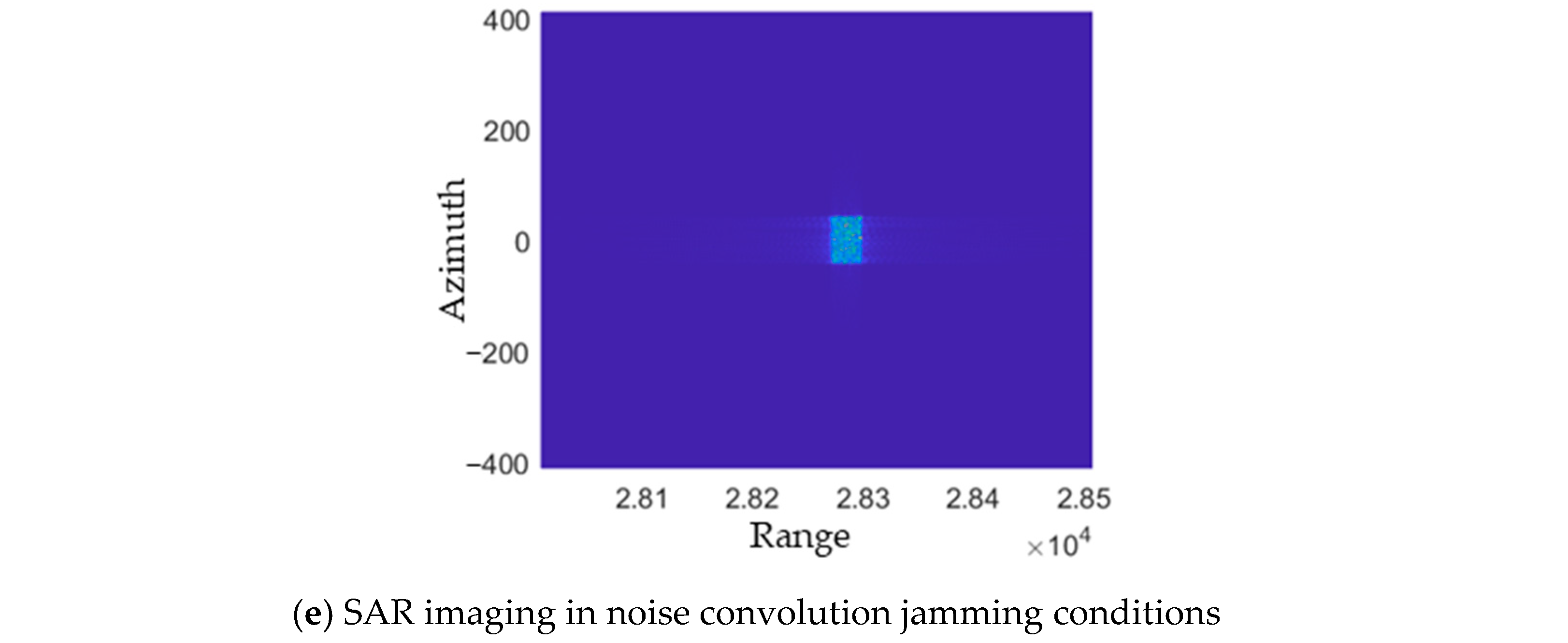
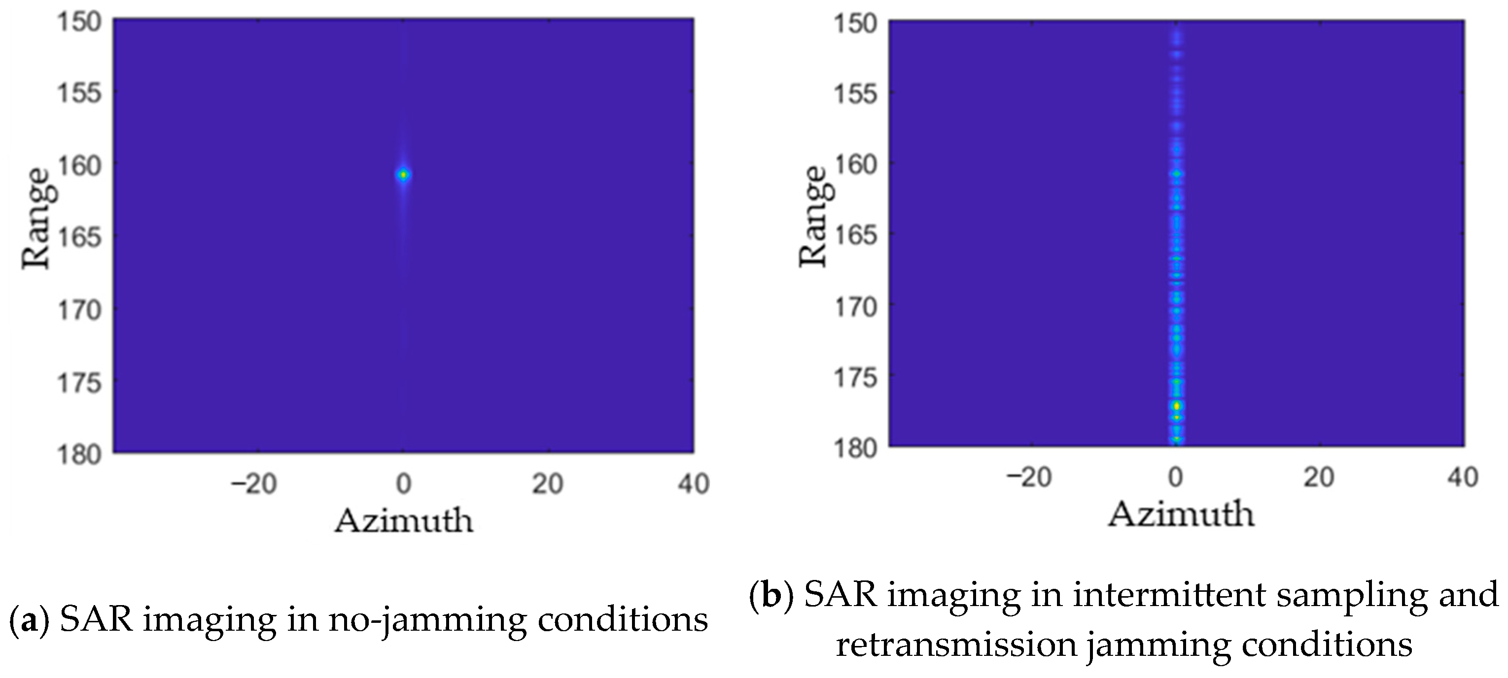
SAR is an advanced microwave imaging system, characterized by its all-weather, all-the-time, high processing gain, and strong anti-jamming capabilities. The high-precision target images it generates provide strong support for intelligence reconnaissance.
Its principle is shown in Figure 10, the aircraft icon is the airborne SAR, and the red dot is the target. SAR systems acquire information about the ground by transmitting radar beams toward it and receiving the returned radar signals. Unlike traditional radars, the antenna in a SAR system is a synthetic aperture, which gathers signals received from different positions to synthesize an image. The basic principle of synthetic aperture is to use the relative motion between the radar and the target to transform a small physical antenna aperture into a larger equivalent virtual antenna, thereby obtaining radar image data with a high azimuth resolution. It works by using a relatively short antenna that, while flying in a straight line, receives and stores the echo signals from the same target at different locations. After the radar has moved a certain distance, it eliminates the phase differences caused by the different times and distances of the received signals from the same target, and corrects them as if they were received simultaneously, much like an antenna array. This synthetic method can greatly improve the resolution of the image, allowing us to observe ground details more clearly.
Its application value has been tested in practice. With its high-resolution imaging of stationary ground targets and the ability to indicate moving ground targets with the support of Ground Moving Target Indication (GMTI) technology, SAR is widely used in fire guidance and “reconnaissance-strike integrated” systems. Therefore, the jamming against SAR has been pushed to the forefront of radar jamming technology.

4.3.2. Jamming

Around the 1990s, Goji from the United States [55] and Condley from the United Kingdom [56] took the lead in researching jamming SAR with noise signals, analyzing the impact of the jammer’s spatial position and jamming power on the effectiveness of the jamming. In China, Liang from Xidian University [57,58] proposed, in 1995, the use of blocking, directed, and random pulse jamming methods against SAR, and analyzed their jamming effects. During this period, other scholars’ research was similar, mainly using noise signals as jamming signals, to reduce the imaging SNR, overwhelming the target echoes with high-power incoherent noise, thus achieving suppression within the radar’s detectable azimuth. However, such jamming methods require high power from the jammer transmitter and can easily reveal the deployment direction of the jammer.
Subsequently, with the development of DRFM, to also achieve a matched-filtering gain with the jamming, research began to focus on deceptive jamming and smart noise jamming based on retransmission jamming. In SAR imagery, each point corresponds to a certain level of reflectivity, delay, and Doppler shift [59]. Therefore, the jammer must produce corresponding reflectivity, delay, and Doppler shift for each point; otherwise, precise jamming of point targets cannot be achieved [35,60]. Ref. [61] was the first in China to research the delay and Doppler shift required for the retransmission signal when adding false targets at specific points. From a time domain perspective, this involves convolving the radar signal with an impulse signal and multiplying it with a frequency-shifted signal. Convolution and multiplication have since been introduced into the study of SAR jamming signals. From this, specialized convolution-based deceptive jamming for false targets or scenarios [62] and jamming using convolving radar signals with noise templates [63,64] have emerged. In the frequency domain, there are fast and slow-time dimensional frequency shift jamming and smart noise jamming that work by multiplying radar signals with noise [17], as well as motion modulation jamming that combines convolution and multiplication [65], and micro-movement jamming, such as vibration, rotation, and acceleration [66]. That is shown in Figure 11.
During the same period, intermittent sampling and retransmission jamming technology was proposed [24], and it attracted the attention of researchers due to its characteristic of generating multiple false targets. In ref. [67], Wu and others conducted a study on the effects of intermittent sampling and retransmission jamming on SAR. However, intermittent sampling and retransmission jamming actually involve regular time delays of pulse segments in the fast-time domain, resulting in significant jamming in the range direction, but which is not yet apparent in the azimuth direction. Therefore, based on the principle of intermittent sampling and retransmission jamming, Wu also proposed intermittent sampling and retransmission jamming targeted in the azimuth direction [68]. The essence of this is to increase the time length to achieve sampling and retransmission in terms of the slow-time dimension. That is shown in Figure 12.
To fully leverage the advantages of various jamming techniques, people have combined different jamming methods to form a composite SAR jamming approach. For instance, to address the lack of flexibility in regard to passive jamming and the lack of stability in regard to active jamming for Synthetic Aperture Radar Moving Target Indication (SAR-GMTI) systems, ref. [69] proposed an innovative large-area masking active–passive coordinated jamming method. In regard to this method, passive jamming is achieved by using a rotating corner reflector in an L-shaped configuration, while active jamming is accomplished through a combination of motion modulation and intermittent sampling jamming. This method uses passive jamming as the mainstay, with active jamming serving as a supplement, working in coordination. Because active jamming can effectively fill the jamming elimination areas of passive jamming, this method can successfully implement large-scale masking jamming against SAR-GMTI systems.
Ref. [70] proposed a jamming waveform that combines comb spectrum modulation and micro-Doppler modulation [71], as well as smart noise jamming [31], to address issues such as insufficient jamming area using coherent suppression jamming and high transmission power requirements using incoherent suppression jamming for SAR. Inspired by the combination of smart noise signals with comb spectrum and micro-Doppler modulation signals, which can produce jamming patterns in SAR imaging results, this method combines the three approaches to achieve a partial compression gain in both range and azimuth directions, creating a larger jamming area. It allows for the adjustment of the jamming parameters based on the characteristics of the ground echo in the suppression area to meet the jamming requirements. However, in terms of evaluating the jamming effect, it still relies on visual observation by the human eye, making it difficult to set objective and quantifiable parameters for the jamming waveform.
Looking at the development history, jamming of SAR has mainly evolved from jamming with a receiver using noise signals, to jamming with matched-filtering processing using coherent signals, and then to precise jamming involving the entire post-processing of imaging. In terms of image quality, this evolution has progressed from degrading the overall quality of the image, to creating false targets or jamming bands in a specific dimension, and then to the process of masking a certain area or transferring specific jamming scenarios.

4.4. Comparative Analysis

The jamming techniques against these typical radar systems have all gone through a process of evolution from non-coherent to coherent jamming, which also demands higher requirements in terms of the reconnaissance parameters. Pulse compression radar, PD radar, and SAR are typical radar systems designed for range measurement, velocity measurement, and imaging, respectively. However, the starting point for jamming them is essentially the same: to overwhelm real targets with noise or smart noise to affect target detection, or to interfere with the judgment of real targets by using false targets.
Since pulse compression radar processes individual pulses, jamming is also limited to the design of jamming for single pulses. The other two, especially SAR, achieve their functions through the post-processing of multiple echoes. Jamming with a single echo does not significantly affect the overall functionality of the technique. Therefore, from the perspective of slow time, designing jamming signals over multiple slow-time intervals is necessary to achieve the jamming effect. A specific comparison of jamming technique performance is shown in Table 3 below.

5. Classification Based on the Stage of Jamming Action

Radar jamming is the targeted treatment of the “weaknesses” that occur during each processing stage, which hinders the normal operation of radar. Taking filters as an example, to improve the SNR and filter out jamming from other frequency bands, radars are designed with corresponding band-pass filters. From the perspective of the jammer, it is necessary to design noise signals that can pass through narrowband filters. To improve the utilization rate of noise power, narrowband noise signals are commonly used. To enhance the coverage effect of noise signals on echo signals, the power spectral distribution of colored noise is designed [4]. To counter anti-jamming measures wherein radars operate on multiple frequency points simultaneously or use frequency hopping, colored noise is processed with a comb spectrum. This allows it to efficiently cover the multiple frequency points commonly used by radars [12].
However, with the introduction of matched filters, the effectiveness of non-coherent signals, such as Gaussian noise, is greatly reduced. Therefore, researchers, with the aid of DRFM technology, have vigorously developed coherent jamming techniques, such as retransmission and smart jamming, so that the jamming signals can also achieve a processing gain after matched filtering. In ref. [71], a smart jamming method for pulse compression radar is proposed, wherein, in the range dimension, the radar signal is modulated with preset multiplicative noise to generate jamming signals with a certain degree of coherence. Refs. [40,41,42,43,72] also focus on interfering with the matched-filtering process, designing waveforms that affect the imaging results in regard to the range dimension.
With the introduction of technologies such as PD radar and SAR, the processing of echo pulse signals has evolved from single-pulse processing to multi-pulse processing. In addition to range information, radars can also extract velocity, direction, and other information from the processing of multiple pulse echoes. It is difficult to produce jamming in multiple dimensions relying solely on methods that interfere with the pulse compression process. For example, ref. [61] mentions that retransmission signals without added delay, according to certain characteristics, do not appear as false targets in SAR images. In ref. [67], Wu has verified that traditional intermittent sampling and retransmission jamming can only produce strip jamming signals in regard to the range dimension of SAR images, and such one-dimensional jamming signals are easily filtered out. Therefore, jamming for these new types of radar systems must focus on interfering with coherent pulse trains, using complex modulation methods for jamming signals to disrupt their signal processing process. In ref. [71], random phase modulation is added on the basis of range dimension jamming to achieve jamming in the range–Doppler two-dimensional domain for PD radar. Ref. [73] proposes various frequency-shift jamming methods for SAR and analyzes the differences in the jamming effects brought about by frequency shifts in the fast-time and slow-time dimensions.

6. Summary

Radar jamming waveform design, as a crucial force in curbing the effectiveness of radar, is of significant importance for the protection of vital targets in the information age. With the continuous advancement of radar technology, radar jamming techniques also need to be innovated to meet new challenges. This paper reviews the main methods and strategies for radar jamming waveform design, including colored noise jamming, comb spectrum jamming, and intermittent sampling and retransmission jamming. These technologies have demonstrated their respective advantages and application prospects in regard to different radar systems. For various radar systems, such as synthetic aperture radar, pulse compression radar, and PD radar, the design of jamming waveforms also exhibits diverse characteristics. Finally, starting from the stages of jamming action, this paper elaborates on the stages wherein various types of jamming mainly take effect and analyzes the mechanisms through which they are effective.
In conclusion, the development of jamming waveforms shows a trend from crude noise jamming to jamming with post-processing, from single-pulse jamming to multi-pulse jamming, and from suppressive jamming to deceptive jamming. Although noise jamming requires a small number of reconnaissance parameters and is adaptable, it demands high transmitter power. In contrast, coherent multi-pulse jamming methods can utilize signal processing gains to greatly improve energy utilization. Due to the advancement of radar technology, its sensing dimensions have greatly increased, and its anti-jamming capabilities have also been enhanced. New jamming methods must be able to confuse radar in multiple dimensions or use dense false targets to combine suppression and deception, thereby disrupting radar judgment.
Currently, there are still several issues in regard to the design of radar jamming waveforms:
First, there is a need to strengthen the connection between jamming evaluation and radar signal processing, to construct more universal and mathematically based evaluation criteria to guide the design of jamming waveforms. As mentioned in Section 3.4, the methods based on statistical perspectives and the parameters calculated from the radar receiver processing results do not apply to different jamming patterns and radars with different functions. Moreover, the method of observing the radar processing results with the naked eye is too subjective. Therefore, it is necessary to construct a more widely applicable and quantifiable evaluation criterion to promote the development of jamming waveform design.
Second, there is a need to enhance the combination of various jamming modulation methods to meet different requirements. In Section 2, the proposed general formula can guide the generation of new combinations of jamming patterns, such as research on large-scale jamming in designated imaging areas of SAR and research on jamming waveform design for radars using specific anti-jamming measures.
Third, there is a need to introduce machine learning algorithms more extensively to make radar jamming waveform design more intelligent and adaptive, improving the real-time and efficient nature of jamming waveform design to cope with complex and changing electromagnetic environments.

Author Contributions

Conceptualization, Y.P. and X.W.; methodology, Y.P. and X.W.; software, Y.P. and D.X.; validation, Y.P. and Y.Z.; formal analysis, D.X.; investigation, X.W.; resources, Z.H.; data curation, Z.H.; writing—original draft preparation, Y.P.; writing—review and editing, Y.P.; visualization, Y.P. and D.X.; supervision, Y.P.; project administration, Z.H. All authors have read and agreed to the published version of the manuscript.

Funding

This research received no external funding.

Data Availability Statement

The results of this paper are simulated and reproduced, and the data is not published.

Conflicts of Interest

The authors declare no conflict of interest.

References

  1. Joint Chiefs of Staff. Electronic Warfare. 2023, JP 3-13.1. Available online: https://edocs.nps.edu/dodpubs/topic/jointpubs/JP3/JP3_13_1_070125.pdf (accessed on 31 January 2024).
  2. Skolnik, M.I. Radar Handbook, 3rd ed.; McGraw-Hill: New York, NY, USA, 2008. [Google Scholar]
  3. Haykin, S. Cognitive radar: A way of the future. IEEE Signal Process. Mag. 2006, 23, 30–40. [Google Scholar]
  4. Wang, L. Adaptive Waveform Design Based on Information Theory. Ph.D. Thesis, National University of Defense Technology, Changsha, China, 2015. [Google Scholar]
  5. Bell, M.R. Information theory and radar waveform design. IEEE Trans. Inf. Theory 1993, 39, 1578–1597. [Google Scholar] [CrossRef]
  6. Romero, R.A.; Bae, J.; Goodman, N.A. Theory and application of SNR and mutual information matched illumination waveforms. IEEE Trans. Aerosp. Electron. Syst. 2011, 47, 912–927. [Google Scholar]
  7. He, P.; Zhao, L.; Zhou, S.; Niu, Z. Water-filling: A geometric approach and its application to solve generalized radio resource allocation problems. IEEE Trans. Wirel. Commun. 2013, 12, 3637–3647. [Google Scholar] [CrossRef]
  8. Zhu, Z.; Kay, S.; Raghavan, R.S. Information-theoretic optimal radar waveform design. IEEE Signal Process. Lett. 2017, 24, 274–278. [Google Scholar]
  9. Chen, J.; Wang, F.; Zhou, J. Information content based optimal radar waveform design: LPI’s purpose. Entropy 2017, 19, 210. [Google Scholar] [CrossRef]
  10. Yan, Z.; Wu, C.; Chen, X.; Zeng, X.; Chen, Y. Research on coherent multi-false-target jamming technology based on comb spectrum modulation. Mod. Radar 2017, 39, 85–88. [Google Scholar]
  11. Zhang, M.; Zhang, W.; Lu, M. Design of random phase multi-frequency point cyclic superposition comb spectrum jamming waveform. Aerosp. Def. 2023, 6, 74–79. [Google Scholar]
  12. Shen, A.; Jiang, Q. Comb spectrum jamming technology for ultra-wideband radar without carrier frequency. Syst. Eng. Electron. 2009, 1, 66–68. [Google Scholar]
  13. Shen, A.; Jiang, Q. Broadband SAR subband pulse modulation comb spectrum jamming technology. Mod. Radar 2014, 1, 6–10. [Google Scholar]
  14. An, K.; Yang, T. Neural network-based optimization technology for peak-to-average power ratio of comb spectrum signals. J. Acad. Electron. Inf. Eng. 2020, 15, 566–572. [Google Scholar]
  15. Spector, S.C. A Coherent Microwave Memory Using Digital Storage: The Loopless Memory Loop; Electronic Warfare: New York, NY, USA, 1975. [Google Scholar]
  16. Tang, L.; Huang, J. Research on smart noise jamming for linear frequency-modulated pulse compression radar. Electron. Countermeas. 2008, 1, 14–17. [Google Scholar]
  17. Huang, D.; Xing, S.; Li, Y.; Liu, Y.; Xiao, S. SAR smart jamming method based on product modulation. Syst. Eng. Electron. 2021, 43, 3160–3168. [Google Scholar]
  18. Zhu, Y.; Zhao, G. Effect analysis of range target image deception jamming. J. Electromagn. Waves Appl. 2006, 1, 131–134. [Google Scholar]
  19. Zhang, W.; Zhou, X.; Tan, Y. Effect analysis of range false target deception jamming for fire control radar. Sichuan Ordnance J. 2007, 4, 40–42. [Google Scholar]
  20. Zhang, Y.; Gao, M.; Li, Y.; Yuan, Q. Digital implementation of multi-false-target jamming in velocity domain. J. Beijing Inst. Technol. 2009, 29, 59–62. [Google Scholar]
  21. Wei, S. Research on Active Efficient Deception Jamming Mechanism and Method for MIMO Radar. Master’s Thesis, University of Electronic Science and Technology of China, Sichuan, China, 2013. [Google Scholar]
  22. Gan, D.; Meng, L.; Guo, H. Brief analysis of range-Doppler false target jamming based on DRFM. Spacecr. Electron. Countermeas. 2005, 1, 25–27. [Google Scholar]
  23. Shi, C.; Wen, W.; Song, H.; Tian, D.; Zhou, J. Research on Delay Error of UAV Swarm Repeater Deception Jamming against Networked Radar. Aero Weapon. 2024, 31, 131–137. [Google Scholar]
  24. Wang, X.; Liu, J.; Zhang, W. Mathematical principles of intermittent sampling and retransmission jamming. Chin. Sci. Bull. 2006, 36, 891–901. [Google Scholar]
  25. Liu, J.; Wang, X.; Liu, Z.; Yang, J.; Wang, G. Leading false target group jamming for linear frequency-modulated pulse compression radar. J. Electron. Inf. Technol. 2008, 30, 1350–1353. [Google Scholar] [CrossRef]
  26. Liu, Z.; Liu, J.; Wang, X.; Wang, G. Analysis of intermittent sampling and retransmission jamming signals. Electron. Countermeas. 2007, 6, 19–23. [Google Scholar]
  27. Pan, X.; Liu, X.; Chen, J.; Feng, X.; Gu, Z.; Xiao, S. Review of Intermittent Sampling and Retransmission Jamming Technology. Syst. Eng. Electron. 2024, 46, 2887–2901. [Google Scholar]
  28. Luan, L. Simulation and Modeling Study of Smart Noise Jamming. Master’s Thesis, Xidian University, Xi’an, China, 2009. [Google Scholar]
  29. Yun, J.; Zhu, Y.; Jin, X. Peak-to-average power ratio improvement method for dense false target jamming. Shipborne Electron. Countermeas. 2012, 2, 54–57. [Google Scholar]
  30. Shen, H.; Wang, X.; Rong, J. Research on smart noise jamming waveform based on DRFM. Spacecr. Electron. Countermeas. 2007, 1, 62–64. [Google Scholar]
  31. Lu, K.; Wang, Y.; Liu, J. Research and simulation of smart noise waveform design. Piezoelectrics Acoustooptics 2009, 31, 757–759. [Google Scholar]
  32. Chen, Q. Simulation Study of Smart Noise Jamming. Master’s Thesis, Nanjing University of Science and Technology, Nanjing, China, 2007. [Google Scholar]
  33. Zhou, Y.; Zhang, J.; He, P. A radar jamming technology—smart noise jamming. Radar Countermeas. 2002, 1, 12–16. [Google Scholar]
  34. Tang, L.; Huang, J.; Xu, X. A smart noise jamming method for LFM pulse compression radar. Spacecr. Electron. Countermeas. 2008, 2, 34–37. [Google Scholar]
  35. Li, W.; Liang, D.; Dong, Z. Research on SAR jamming technology based on deceptive moving targets. Remote Sens. 2006, 1, 71–75. [Google Scholar]
  36. Liu, G.; Zhang, Q.; Huang, Z.; Chen, T.; Mu, B.; Guo, H. SAR Imaging of Dense False Target Jamming Based on Phase Modulation. IEEE Geosci. Remote Sens. Lett. 2025, 22, 1–5. [Google Scholar]
  37. Pan, X.; Wang, W.; Feng, D.; Fu, Q.; Wang, G. LFM radar jamming method based on full pulse segmentation and retransmission. J. Natl. Univ. Def. Technol. 2013, 3, 119–125. [Google Scholar]
  38. Wang, Y.; Zhao, G. N-order SSC blind frequency-shift jamming algorithm for LFM radar. J. Circuits Syst. 2011, 16, 70–74. [Google Scholar]
  39. Xiao, J.; Wei, X.; Sun, J. Interrupted-sampling multi-strategy forwarding jamming with amplitude constraints based on simultaneous transmission and reception technology. Digital Signal Process. 2024, 147, 104416. [Google Scholar] [CrossRef]
  40. Zhang, Y. Waveform Optimization Design of Intermittent Sampling and Retransmission Jamming. Master’s Thesis, Harbin Engineering University, Harbin, China, 2022. [Google Scholar]
  41. Chen, T.; Zhang, Y.; Hu, X.; Xiao, Y. Waveform optimization design for detection and jamming integration based on DQN. Syst. Eng. Electron. 2023, 45, 638–646. [Google Scholar]
  42. Chen, T.; Zhang, Y.; Huang, X. Adaptive jamming waveform design based on reinforcement learning. Aerosp. Def. 2021, 4, 59–66. [Google Scholar]
  43. Hao, W.; Zhang, J.; Chen, J. Research on a non-uniform combined intermittent sampling and retransmission jamming method. Fire Control Radar Technol. 2023, 52, 87–91. [Google Scholar]
  44. Zhang, J.; Li, W.; Sun, W.; Wang, H. Optimization of phase-coded radar jamming waveform based on particle swarm optimization algorithm. Mod. Electron. Technol. 2023, 46, 27–32. [Google Scholar]
  45. Zhang, L. Research on New Jamming Technology for Phase-Coded Radar. Master’s Thesis, National University of Defense Technology, Changsha, China, 2008. [Google Scholar]
  46. Xu, L.; Feng, D.; Zhao, J.; Zhang, W. Leading false target jamming for phase-coded radar systems. J. Astronaut. 2013, 1, 133–138. [Google Scholar]
  47. Lai, Z.; Gao, Y.; Wan, J.; Zhou, Y. Research on dense false target jamming for phase-coded radar. J. Air Force Early Warn. Acad. 2016, 4, 267–270. [Google Scholar]
  48. Zhang, X.; Xiao, K.; Gu, J. New System Radar Confrontation Theory; Beijing Institute of Technology Press: Beijing, China, 2020. [Google Scholar]
  49. Lv, B.; Feng, Q.; Zhang, X.; Yuan, N. Research on random pulse convolution jamming for SAR. J. Acad. Electron. Inf. Eng. 2008, 3, 276–279. [Google Scholar]
  50. Lu, J.; Li, J.; Huang, G. Noise jamming research for pulse Doppler radar. Shipborne Electron. Countermeas. 2010, 33, 15–19. [Google Scholar]
  51. Cheng, L.; Xie, D.; Jiang, D.; Zhang, Y. Simulation study of pulse Doppler radar jamming based on SystemVue. Shipborne Electron. Countermeas. 2017, 50, 72–77. [Google Scholar]
  52. Lu, M. Research on Pulse Doppler Radar Jamming Technology. Master’s Thesis, Xidian University, Xi’an, China, 2005. [Google Scholar]
  53. Yang, H.; Cheng, Q.; Jiang, S.; Wang, J. Research on pulse Doppler radar jamming modulation technology. Electron. Compon. 2023, 46, 1225–1229. [Google Scholar]
  54. Yang, Z. Research on Pseudo-Code Phase Modulation Pulse Doppler Fuze Jamming Technology. Master’s Thesis, Xidian University, Xi’an, China, 2023. [Google Scholar]
  55. Goj, G. Synthetic-Aperture Radar and Electronic Warfare; Artech House: Boston, MA, USA, 1993. [Google Scholar]
  56. Condley, C. Some system considerations for electronic countermeasures to synthetic aperture radar. In Proceedings of the IEE Colloquium on Electronic Warfare Systems, London, UK, 14 January 1991. [Google Scholar]
  57. Liang, B. NMD-GBR radar jamming waveform design. Spacecr. Electron. Countermeas. 2007, 23, 5–7. [Google Scholar]
  58. Liang, B. Jamming for synthetic aperture radar. Shanghai Aerosp. 1995, 1, 37–42+47. [Google Scholar]
  59. Wu, X.; Dai, D.; Wang, X.; Lu, H. SAR azimuth Doppler modulation jamming. Mod. Radar 2010, 1, 55–60. [Google Scholar]
  60. Bo, Z.; Lei, H.; Bing, L.; Shi, L.; Wei, B. One-bit splitting deceptive jamming against SAR. Def. Technol. 2022, 18, 1760–1777. [Google Scholar]
  61. Wang, S.; Yu, L.; Ni, J.; Zhang, G. Research on active deception jamming methods for synthetic aperture radar. Acta Electron. Sin. 2003, 2, 1900–1903. [Google Scholar]
  62. Ji, P.; Xing, S.; Dai, D.; Xu, W.; Pang, B.; Feng, D. SAR convolution deception jamming method based on inverse chirp scaling. J. Electromagn. Waves Appl. 2023, 38, 1029–1039. [Google Scholar]
  63. Ji, P.; Xing, S.; Dai, D.; Pang, B.; Feng, D. SAR range convolution azimuth product modulation scene deception jamming method. J. Aeronaut. 2023, 44, 242–259. [Google Scholar]
  64. Huang, D.; Xing, S.; Liu, Y.; Li, Y.; Xiao, S. New method for generating false signals in SAR based on noise convolution modulation. J. Radars 2020, 9, 898–907. [Google Scholar]
  65. Wu, X.; Wang, X.; Liang, J. High-fidelity uniform motion false target modulation jamming method for SAR-GMTI. J. Astronaut. 2012, 10, 1472–1479. [Google Scholar]
  66. Wu, X.; Dai, D.; Wang, X.; Lu, H. A novel active jamming method for SAR based on micro-motion modulation. Acta Electron. Sin. 2010, 4, 954–959. [Google Scholar]
  67. Wu, X.; Wang, X.; Lu, H. Research on intermittent sampling and retransmission jamming for SAR. J. Astronaut. 2009, 5, 2043–2048, 2072. [Google Scholar]
  68. Wu, X.; Bai, Z.; Dai, D.; Wang, X. Azimuth intermittent sampling and retransmission jamming for SAR. Signal Process. 2010, 1, 1–6. [Google Scholar]
  69. Zhou, Y.; Bi, D.; Shen, A. Large-area masking active-passive coordinated jamming method for SAR-GMTI. Syst. Eng. Electron. 2018, 40, 1004–1011. [Google Scholar]
  70. Song, J.; Zhang, H.; Zheng, F. Micro-motion modulation-based comb spectrum smart noise suppression jamming. Radar Sci. Technol. 2020, 18, 531–538+545. [Google Scholar]
  71. Wu, J.; Ji, X.; Wang, X.; Xiong, B.; Li, B. A practical noise jamming method for pulse compression Doppler radar. Electron. Inf. Countermeas. Technol. 2022, 37, 55–59. [Google Scholar]
  72. Wu, Z. Cognitive Electronic Countermeasure Jamming Waveform Design. Master’s Thesis, Xidian University, Xi’an, China, 2018. [Google Scholar]
  73. Huang, H.; Huang, Z.; Zhou, Y. Research on frequency-shift jamming for synthetic aperture radar. J. Astronaut. 2006, 3, 463–469. [Google Scholar]
Figure 1. Jamming process.
Remotesensing 17 01218 g001
Figure 2. Comb spectrum jamming signal.
Remotesensing 17 01218 g002
Figure 3. DRFM process diagram.
Remotesensing 17 01218 g003
Figure 4. Schematic diagram of intermittent sampling and single repetition jamming waveform.
Remotesensing 17 01218 g004
Figure 5. Schematic diagram of intermittent sampling and repeated repetition jamming.
Remotesensing 17 01218 g005
Figure 6. Schematic diagram of intermittent sampling and sequential cyclic repetition jamming.
Remotesensing 17 01218 g006
Figure 7. Schematic diagram of non-uniform intermittent sampling and repetition jamming.
Remotesensing 17 01218 g007
Figure 8. Schematic diagram of pulse compression radar.
Remotesensing 17 01218 g008
Figure 9. Schematic diagram of PD radar.
Remotesensing 17 01218 g009
Figure 10. Schematic diagram of SAR.
Remotesensing 17 01218 g010
Figure 11. SAR jamming effect diagram.
Remotesensing 17 01218 g011aRemotesensing 17 01218 g011b
Figure 12. Comparison of SAR intermittent sampling and retransmission jamming effects.
Remotesensing 17 01218 g012
Table 1. General jamming formula table.
Jamming TechniqueParametersTarget
a 1 a 2 a 3 a 4 G t , τ g t , τ f t , τ
Colored Noise0001/0/No specific target
Comb Spectrum Jamming0001/Comb spectrum frequency shift formula/No specific target
Trailing Range False Target Jamming0010/Doppler couplingIncreasing Time DelayPD radar
Non-Trailing Range False Target Jamming0010//Fixed Time DelayNo specific target
Velocity False Target Jamming0010/Doppler frequency shift (including velocity trailing, jitter, rotational micro-movement jamming, etc.)Range CouplingPD radar
Azimuth False Target Jamming0010/Slow-time frequency shift can achieve false targets in the azimuth direction of Synthetic Aperture Radar (SAR)Time AlignmentSAR
Intermittent Sampling and Repetition Jamming0010Sampling width (variable when non-uniform sampling is used)/Transmission TimingNo specific target
Convolutional Jamming0100//Time AlignmentNo specific target
Multiplicative Jamming1000//Time AlignmentNo specific target
Note: To meet various jamming requirements, multiple types of jamming can be combined and modulated.
Table 2. Comparison of jamming technique performance.
Jamming TypeJamming TechniqueJamming EffectRequired Prior ParametersAdvantagesDisadvantages
Barrage JammingNarrowband Colored Noise [4]Reduces SNR, uses colored noise to overwhelm echoes, and decreases detection probability.1. Radar Carrier Frequency
2. Radar Bandwidth
3. Radar Signal Power Spectral Distribution
1. In terms of frequency, the jamming energy is more concentrated than in blocking jamming.
2. Fewer prior parameters are required, and the jamming signal is easy to generate.
1. The generated jamming signal is non-coherent.
2. When targeting fixed frequency points, it is not flexible.
Comb Spectrum Jamming [12,13,14]Targets multiple frequency points, reduces SNR, uses colored noise to overwhelm echoes, and decreases detection probability.1. Multiple Frequency Points of Radar Operation
2. Signal Bandwidth
3. Power Spectral Characteristics
Can release colored noise targeting radar signal frequency hopping or multiple frequency points operating simultaneously.1. Requires the jammer’s transmitter and receiver bandwidth to be relatively large.
2. The superposition of signals interfering with multiple frequency points may result in an excessively high PAPR, affecting engineering implementations.
Deceptive JammingDeceptive Jamming with Complete Pulses [16,17,18,19,20,21,22,23]Generates false targets in terms of range, azimuth, or velocity.1. Carrier Frequency
2. Intercepted Radar Pulse
3. Pulse Repetition Interval
4. Frequency Modulation Slope
5. Distance and Relative Motion Relationship between Radar, Jammer, and False Target
1. Can produce deceptive jamming signals highly similar to real target echoes.
2. The azimuth and velocity of false targets are controllable.
3. The jamming signal is highly coherent with the radar signal, requiring low jamming power.
1. Requires high-quality intercepted pulses.
2. Requires many prior parameters.
3. When designing multiple false targets with different distributions and motion patterns, the parameters need to be adjusted one by one, the calculation is complex, and the PAPR is difficult to control.
4. When using modulation, such as rotation and micro-motion, the distribution pattern of multiple false targets is impacted.
Intermittent Sampling and Repetition Jamming [24,25,26,27]Forms a series of regularly distributed false targets in regard to range direction.Intercepted Radar Pulse1. Requires fewer parameters.
2. Can quickly generate multiple false targets, with strong real-time performance.
3. The jamming signal is coherent, requiring low jamming power.
4. Solves the antenna transmitter and receiver isolation problem of the jammer, with a low PAPR.
1. The distribution pattern of false targets is regular and easily recognizable.
2. The utilization rate of the jamming time is low, and the jamming effect is easily affected by the sampling and retransmission rules and duty cycle.
Smart Noise JammingSmart Noise Jamming by Modulating Complete Pulses [16,28,29,30,31,32,33,34,35]Generates suppressive jamming in the range or imaging area.1. Carrier Frequency
2. Intercepted Radar Pulse
3. Pulse Repetition Interval
4. Distance and Relative Motion Relationship between Radar, Jammer, and False Target
Can produce highly realistic points, area deception, or suppression jamming.It depends on many parameters, has a large computational load, and has poor real-time performance.
Smart Noise Jamming by Modulating Pulse Segments [40,41,42,43,44,45,46,47]Produces suppressive jamming in range or specific imaging areas.1. Carrier Frequency
2. Intercepted Radar Pulse
3. Pulse Repetition Interval
4. Distance and Relative Motion Relationship between Radar, Jammer, and False Target
It can produce highly realistic point, area deception, or suppression jamming (intermittent sampling and retransmission jamming can only produce range jamming). 1. The signals generated by equidistant sampling and pulse sampling methods mean that it is difficult to address the antenna transmitter and receiver isolation problem and high PAPR issues.
2. In regard to intermittent sampling and retransmission jamming, it is difficult to interfere in the azimuth direction, and the utilization rate of the jamming time is low.
Table 3. Comparison of jamming technique performance.
Jamming TypeJamming TechniqueJamming EffectRequired Prior ParametersAdvantagesDisadvantages
Pulse Compression RadarNoise Jamming [4]Suppresses the energy of the target echo, increases the SNR, and affects target detection.1. Signal Carrier Frequency
2. Signal Bandwidth
Less dependent on reconnaissance parametersHigh power requirements, prone to revealing the jammer’s location.
Intermittent Sampling and Repetition Jamming [24,25,26,27]Forms a series of evenly spaced false point targets.1. Intercepted Radar Pulse
2. Pulse Width
1. Less dependent on parameters
2. Good real-time performance
3. Flexible and variable number and spacing of false targets
4. Solves the problem of transmitter–receiver isolation for the jammer’s antenna
1. The distribution pattern of false targets is regular and easily identifiable.
2. Low utilization rate of jamming time.
3. Prone to being affected by the duty cycle.
Smart Noise Jamming [30,31,32]Can create suppressive dense false targets.1. Intercepted Radar Pulse
2. Pulse Width
3. Pulse Bandwidth
4. Relative Position Relationship between the Jammer and the Radar
1. Flexible modulation methods
2. The jamming signal is coherent with the radar signal, combining deception and suppression
Some modulation methods require a high computational load or have difficulty in suppressing the PAPR.
PD RadarNoise Jamming [50,51]Suppresses the energy of the target echo, increases the SNR, and affects target detection.1. Signal Carrier Frequency
2. Signal Bandwidth
Less dependent on reconnaissance parameters1. High power requirements.
2. Prone to revealing the jammer’s location.
Range–Velocity Deceptive Jamming [52]Can create highly realistic single or multiple range, velocity, or range–velocity false targets for deception.1. Intercepted Radar Pulse
2. Signal Carrier Frequency
3. Signal Pulse Width
4. Signal Bandwidth
5. Pulse Repetition Interval (PRI)
1. Can generate velocity and range false targets, and can also interfere with both velocity and range simultaneously, offering flexible jamming effects
2. Can generate multiple false targets at the same time
1. The current methods for generating multiple false targets in deceptive jamming have a strong regularity, making them easily identifiable.
2. If false target signals are designed individually to create multiple false targets for deception, the computational load is high, and it is difficult to suppress the PAPR.
3. High dependence on parameters.
Intermittent Sampling and Repetition Jamming [54]Forms a series of evenly spaced false point targets in the range direction.1. Intercepted Radar Pulse
2. Pulse Width
1. Less dependent on parameters
2. Good real-time performance
3. The number and spacing of false targets are flexible and variable
4. Solves the problem of transmitter–receiver isolation for the jammer’s antenna
1. The distribution pattern of false targets is regular and easily identifiable.
2. Low utilization rate of jamming time.
3. Prone to being affected by the duty cycle.
4. Difficult to create velocity deception.
Smart Noise Jamming [53,54]Can form dense false targets for suppressive purposes.1. Intercepted Radar Pulse
2. Pulse Width
3. Pulse Bandwidth
4. Relative Position and Velocity Relationship between the Jammer and the Radar
1. Flexible modulation methods
2. The jamming signal is coherent with the radar signal, balancing deception and suppression
1. Some modulation methods have a high computational load, or it is difficult to suppress the PAPR.
2. It is challenging to design the process for different target motions.
SARNoise Jamming [55,56,57,58]Suppresses the energy of the target echo but degrades the image quality.1. Carrier Frequency
2. Bandwidth
1. Less dependent on reconnaissance parameters
2. Wide application range
1. High power requirements.
2. Prone to revealing the jammer’s location.
Convolutional Deceptive Jamming [61]False targets or scenarios.1. Intercepted Radar Pulse
2. Relative Position and Velocity Relationship between the Jammer and the Radar
3. Pulse Repetition Interval (PRI)
4. Carrier Frequency
Generates point, surface, and scenario deception1. High computational load, and poor real-time performance.
2. High dependency on reconnaissance parameters.
Intermittent Sampling and Repetition Jamming [67,68]Evenly spaced false point target strings in the range direction.Intercept Radar Signal1. Less dependent on reconnaissance parameters, with strong real-time capabilities
2. The number and spacing of false targets are flexible and variable
3. Solves the problem of transmitter–receiver isolation for the jammer’s antenna
1. The regularity of the false targets is strong, making them easily identifiable.
2. The utilization rate of the jamming time is relatively low.
3. Prone to being affected by duty cycle.
Frequency-Shift Jamming [66]Forms false point targets, strings of point targets, suppression bands, or suppression areas in the azimuth direction.1. Intercepted Radar Pulse
2. Pulse Width
3. Signal Bandwidth
1. Can create a variety of jamming effects
2. Can cover distributed surface targets and large-scale scenarios
High dependency on reconnaissance parameters.
Motion Modulation Jamming [65,66]Azimuth false targets or suppression stripes.1. Intercepted Radar Pulse
2. Signal Carrier Frequency
3. Relative Position and Velocity Relationship between the Jammer and the Radar
1. The length of the suppression line is variable
2. The spacing and number of false point targets are variable
1. The suppression area is small, making it difficult to cover surface targets.
2. The false targets have a strong regularity, making them easily identifiable.
Smart Noise Jamming [62,63,64]Suppression bands, suppression areas.1. Intercepted Radar Pulse
2. Relative Position and Velocity Relationship between the Jammer and the Radar
3. Signal Carrier Frequency
4. Pulse Width
5. Bandwidth
1. Flexible modulation methods
2. Diverse jamming effects
High computational load, and poor real-time performance for some methods.
Disclaimer/Publisher’s Note: The statements, opinions and data contained in all publications are solely those of the individual author(s) and contributor(s) and not of MDPI and/or the editor(s). MDPI and/or the editor(s) disclaim responsibility for any injury to people or property resulting from any ideas, methods, instructions or products referred to in the content.

