Article

Broadband SAR Imaging Based on Narrowband Dense False Target Jamming

1
School of Electronic Engineering, Xidian University, Xi’an 710071, China
2
Hangzhou Institute of Technology, Xidian University, Hangzhou 311231, China
3
School of Physics, Xidian University, Xi’an 710071, China
*
Author to whom correspondence should be addressed.
Remote Sens. 2025, 17(7), 1196; https://doi.org/10.3390/rs17071196
Submission received: 26 February 2025 / Revised: 22 March 2025 / Accepted: 24 March 2025 / Published: 27 March 2025

Abstract

:
To meet the multi-device integration requirements faced by electronic warfare systems in the current environment and to address the problem of conventional jamming-based imaging algorithms being unable to achieve a high range resolution under narrowband conditions, this paper proposes a broadband high-resolution synthetic aperture radar (SAR) imaging method based on narrowband dense false target jamming signals (DFTJSs). The characteristic of this signal is its ability to modulate large bandwidth phase information for each narrowband false target jamming signal (FTJS) so that the echo of the entire jamming signal has a secondary compression characteristic in the distance direction without affecting its jamming ability, thereby eliminating the influence of the first compression distance blur and obtaining a high resolution of the large bandwidth signal. Theoretical analysis and numerical simulations indicate that narrowband DFTJSs using phase modulation can achieve high-resolution imaging of specific target areas while causing interference to non-cooperative radar (NCR).

1. Introduction

Radar, as an important detection tool, was first invented and applied in the military. It uses a relatively simple pulse system, operates at low frequencies, and has a small detection range [1,2]. With the continuous development of science and technology, modern radar integrates more complex signal design methods and processing techniques, and its application scope has penetrated into various aspects of daily life, including transportation [3], meteorology [4], and navigation [5].
In modern radar applications, there are strict requirements for performance indicators, such as the radar operating range, resolution, and measurement accuracy [6]. Linear frequency modulation (LFM) signals are widely used in various scenarios due to their large time–bandwidth product [7], which brings high resolution. In order to reduce the detection performance of non-cooperative radar (NCR), various effective electromagnetic countermeasures (ECMs) [8,9] have also emerged. These measures are generally divided into active jamming and passive jamming based on the presence of internal radiation sources [10]. With the development of numerical radio frequency memory technology (DRFM), active jamming is widely used due to its high flexibility and effectiveness. This paper focuses on the study of active jamming.
Active jamming can be further divided into suppression jamming [11,12] and deception jamming [13,14]. Suppression jamming injects high-power noise signals into NCR, reducing its signal-to-noise ratio (SNR) to submerge real targets in noise. However, due to the high gain of LFM signal pulse compression (PC), a high jamming power output is required to achieve the expected jamming effect. On the other hand, deception jamming obtains high-gain false target signals by reflecting radar signals to conceal real targets, which requires much less power than suppression jamming. This paper focuses on the study of deceptive jamming.
In order to meet the increasingly strict technical requirements and expanding technological fields of modern radar, new processing technologies, including synthetic aperture radar (SAR), are also constantly developing. SAR can provide two-dimensional high-resolution terrain observations [15,16] and has been widely used in civilian [17,18,19] and military [20,21,22] fields. However, a single radar detection and jamming device is no longer sufficient to meet the development needs of multifunctional integrated devices at present. Radar and jamming systems have many similar parts, and integrating radar and jamming functions can greatly reduce resource consumption.
At present, research on multifunctional waveforms mainly focuses on the dual functions of radar and communication, while there is still a considerable lack of research on the dual functions of radar and jamming. Reference [23] used a Filter-Bank Multicarrier (FBMC) to design Multiple-Input Multiple-Output (MIMO) frequency division signals, enabling jamming signals to have imaging capabilities. Reference [24] studied the integrated multifunctionality of SAR imaging and radar jamming, which first proposed modulating the secondary phase of the false target jamming signal (FTJS) and performing two matched filtering processes during SAR imaging range compression to eliminate the distance blur caused by the FTJS after the first compression. However, the bandwidth of the signal used for secondary compression in this method is limited by the bandwidth of the NCR’s signal. When the NCR uses narrowband signals, they will greatly limit the range resolution of SAR imaging.
In this study, we designed a dense false target jamming signal (DFTJS) based on phase modulation and used a dechirp processing method to reduce the sampling rate required for signal processing during range dimension secondary compression in order to achieve dual functions of radar jamming and high-resolution SAR imaging. Specifically, our SAR platform intercepts NCR signals, generates multiple FTJSs through convolution, and modulates a large amount of bandwidth signal phase information for each FTJS before forwarding it. After PC processing by NCR, the modulated phase information does not affect the jamming effect, which causes the modulated DFTJS to have the same jamming performance as a conventional DFTJS. After receiving the echo of the signal in SAR, an improved range–Doppler (RD) algorithm is used to complete the imaging, which first performs matched filtering compression in the range dimension, and then uses a dechirp processing method for secondary compression to eliminate distance blur and obtain high-resolution range compression results. Then, PC processing is performed in the azimuth direction to form SAR imaging results. The main contributions of this paper are as follows:
  • We designed a broadband SAR imaging signal based on narrowband DFTJSs, and provided the overall signal design process and signal processing methods to solve the problem of limited signal bandwidth in conventional secondary compression processing methods;
  • We studied the system constraints and parameter design of the signal and processing method designed in this paper through a reasonable theoretical analysis;
  • We validated and evaluated the feasibility of this method through simulation experiments, including the jamming and imaging capabilities of the joint signal.

2. Application Scenarios and Signal Model

In this study, we designed a broadband SAR imaging signal based on narrowband DFTJ. The signal transceiver equipment was deployed on an airborne platform to achieve jamming with ground radar and high-resolution imaging of the ground.

2.1. Geometric Scenes

Figure 1 shows the application scenario of the joint signal designed in this study. An unmanned aerial vehicle (UAV) performs SAR imaging on the ground while jamming with NCR (represented by P). The UAV carries an SAR platform with a forward side view configuration, flying at a speed v a along the azimuth direction and performing strip imaging. Meanwhile, P is deployed on the ground for air detection and operating in search mode, emitting narrowband LFM pulse signals. To protect the UAV from detection by P, it is necessary to jam with P. The SAR imaging signal based on narrowband DFTJSs designed in this study can meet the UAV’s requirements for jamming with P while completing ground SAR imaging.

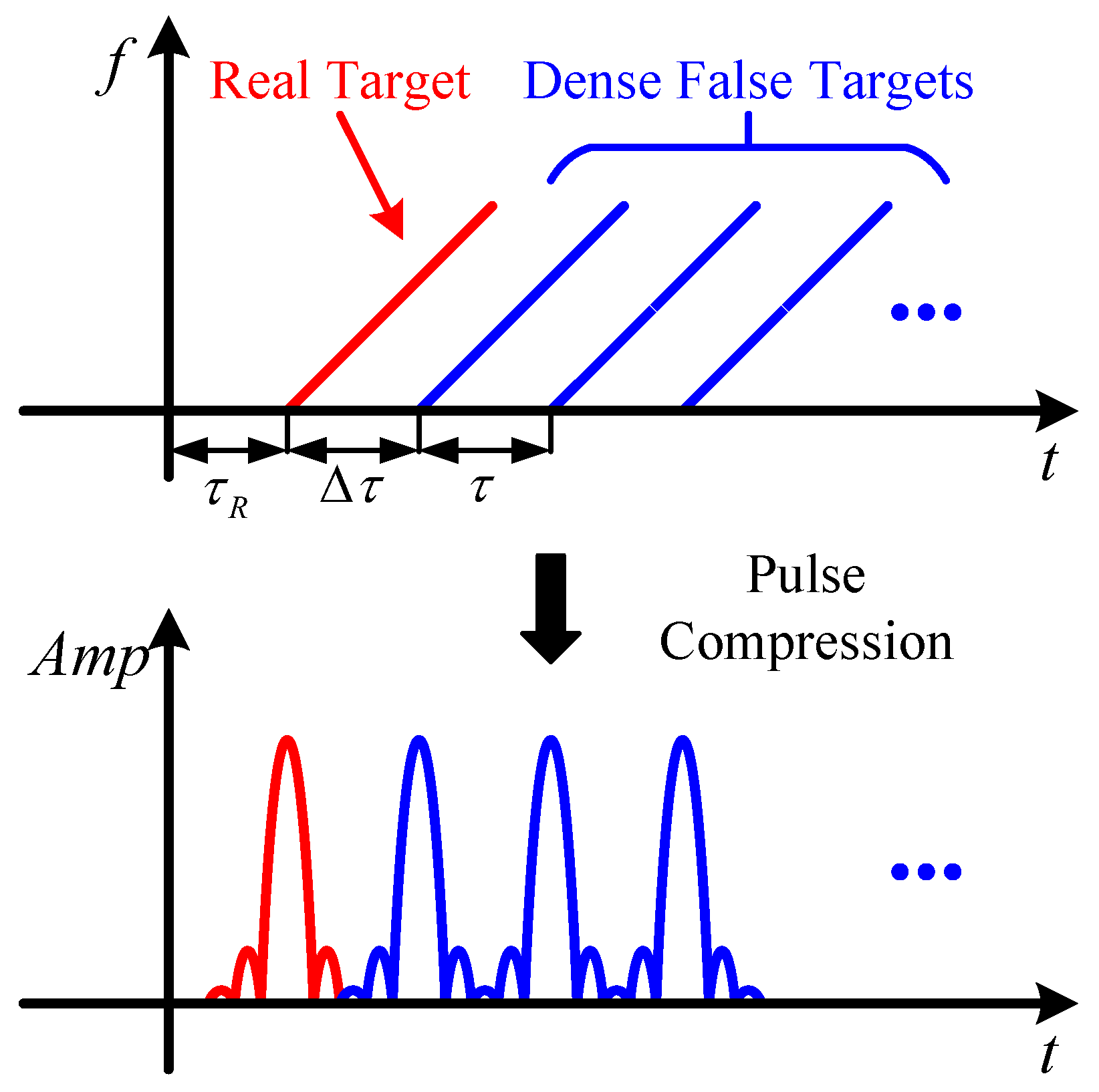
2.2. Narrowband DFTJS Model with Phase Modulation

Assuming P emits an LFM signal with a pulse width of T p , a narrow bandwidth of B, and a carrier frequency of f c , the expression for the signal intercepted by the UAV without considering the propagation delay is
s t = rect t T p exp j π k r t 2 + j 2 π f c t
where rect · represents the rectangular window function and k r = B / T p represents the frequency modulation slope of the LFM signal.
A conventional DFTJS is constructed by convolving the baseband radar signal with the corresponding generation filter g t , which is composed of N impulse response function groups with a fixed time delay τ . The specific expression can be written as
J 1 t = s t g t = rect t T p exp j π k r t 2 n = 0 N 1 δ t n τ exp j 2 π f c t = n = 0 N 1 rect t n τ T p exp j 2 π f c t + j π k r t n τ 2
where ⊗ represents the convolution symbol.
The joint signal designed in this study modulates a large bandwidth secondary phase information on each FTJS, as shown in Figure 2. In this figure, the red line represents the time–frequency diagram of the secondary phase signal, B s represents its bandwidth, and the blue line represents the time–frequency diagram of the FTJS.
The expression for the secondary phase signal is
s c t = rect t T s exp j π k r t 2
where T s = N 1 τ represents the time width of the secondary phase signal.
Sampling s c t at intervals of τ and modulating the sampled values onto the jamming signal obtains the expression of the signal after modulating the secondary phase:
J t = n = 0 N 1 rect t n τ T p exp j 2 π f c t + j π k r t n τ 2 + j π k r n τ 2

3. Jamming Effect Analysis

For the convenience of subsequent calculations, the one-way signal delay from P to the UAV can be ignored. Assume that P receives the echo of the transmitted signal and the jamming signal emitted by the UAV after the transmission interval of τ R and Δ τ + τ R , respectively. Among them, τ R is the delay of the echo and Δ τ is the time difference between the jamming signal and the radar signal caused by the generation time of the jamming signal. After receiving all the signals, P performs standard radar processing procedures on the received signals [25], including orthogonal demodulation, PC, moving target detection (MTD), and constant false alarm rate (CFAR). Without considering the amplitude after the PC, the PC processing result after orthogonal demodulation is
s o u t t = s P t δ t τ R + J t δ t Δ τ τ R exp j 2 π f c t s * t = sinc π B t τ R exp j 2 π f c τ R exp j π k r τ R t exp j 3 π k r τ R 2 + n = 0 N 1 sinc π B t τ R n τ exp j π k r τ R + n τ t j 3 π k r τ R + n τ 2 × exp j π k r n τ 2 exp j 2 π f c n τ + τ R
where sinc t = sin t t . Taking the modulus value produces
s o u t t = sinc π B t τ R + n = 0 N 1 sinc π B t Δ τ τ R n τ
where s * t is the matched filtering function used by the PC, and * represents the conjugate operation. According to Equation (6), the time–frequency structure of the received signal for P and the resulting pattern of the PC are shown in Figure 3.
The red and blue curves in Figure 3 represent the time–frequency and PC results of the true target echo and DFTJS, respectively. Due to the high correlation between the jamming signal and radar echo signal, after the PC processing, the jamming signal will generate a large number of false target peaks after the real target peaks, making it difficult to accurately identify the real target position. In order to minimize the impact of environmental clutter and various human interferences, modern radar often uses the CFAR [26] to ensure a constant false alarm rate, where the cell average CFAR (CA-CFAR) [27] is the most commonly used. At the same time, the amplitude of each false target modulation phase in the jamming signal designed in this study is 1, which does not affect the jamming effect in the PC and CFAR. Its jamming effect is the same as that of a conventional DFTJS. However, it should be noted that the positions of false targets lag behind that of real targets, which is caused by the jamming signal generation method of DFTJSs.

4. SAR Imaging Method

This section introduces the SAR imaging processing method of the joint signal designed in this paper, mainly including the echo signal model, range compression, and azimuth compression.

4.1. SAR Echo Signal Model

The echo signal model received by a UAV is
J r t = J t δ t τ P = n = 0 N 1 rect t τ P n τ T p exp j 2 π f c t τ P × exp j π k r t τ P n τ 2 + j π k r n τ 2
where τ P = 2 R T a 2 R T a c c is a quantity related to slow time T a . Without loss of generality, we assume that P is located at x 0 , y 0 , 0 , the height of the UAV is H, and the shortest distance from the UAV trajectory to point P is R 0 = y 0 2 + H 2 . As the UAV platform moves, the real-time distance between the jammed target P and the SAR can be expressed as
R T a = R 0 2 + x 0 v a T a 2 R 0 x 0 v a T a R 0 + v a 2 T a 2 2 R 0

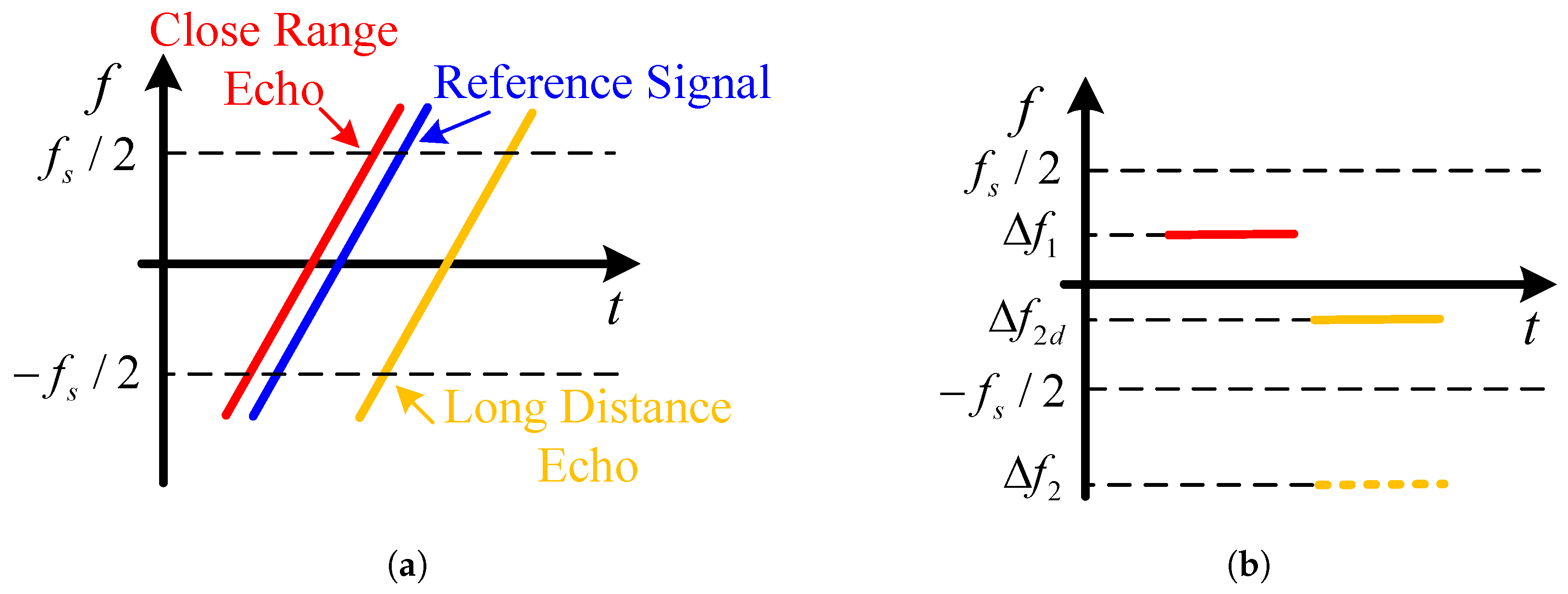
4.2. Range–Secondary Compression Based on Dechirping

First, orthogonal demodulation and matched filtering on J r t in fast time is performed to obtain the processed signal:
J o u t 1 t = J r t · exp j 2 π f c t s * t = n = 0 N 1 A P 1 exp j π k r τ P + n τ t exp j 3 π k r τ P + n τ 2 × sinc π B t τ P n τ exp j π k r n τ 2 exp j 2 π f c τ P
where · represents the multiplication symbol, and A P 1 is the amplitude of the point target echo signal after the first distance direction PC. From the structure shown in Equation (9), it can be seen that the result of the DFTJS after the PC processing is the superposition of multiple discrete sin c functions. If J o u t 1 t is directly used for SAR imaging, it will still produce distance direction blur results. Moreover, the first time-varying exponential term in Equation (9) will affect the subsequent secondary compression processing and needs to be compensated for first.
The phase that needs to be compensated is
ϕ r t = n = 0 N 1 exp j π k r n τ t
The expression of the signal after the phase compensation is
J o u t 1 c t = J o u t 1 · ϕ r * t = n = 0 N 1 A P 1 exp j 3 π k r τ P + n τ 2 sinc π B t τ P n τ × exp j π k r τ P t exp j π k r n τ 2 exp j 2 π f c τ P
After the phase compensation, it is necessary to design a reasonable forwarding interval for false targets to enable them to have secondary compressibility. Due to the fact that the jamming signal after the PC is in the form of multiple sin c functions, the peak value and the interval between adjacent zeros are related to the signal bandwidth, that is 1 1 B B . If the time interval between two adjacent jamming signals is designed to be τ = 1 1 B B , the result of the PC can become the result shown in Figure 4.
From the enlarged blue box in Figure 4, it can be seen that the false target compression results after setting the time interval are orthogonal to each other in the time domain (with the same structure as an Orthogonal Frequency Division Multiplex (OFDM)), after ignoring the influence of the fixed phase. At this point, the entire false target signal superposition can be approximated as a rectangular pulse structure:
J o u t 1 t A P 1 rect t τ p T s exp j 2 π f c τ p × exp j π k r t τ p 2 exp j π k r τ p t τ p
Equation (12) represents the form of the LFM signal, and the signal bandwidth B s = k r T s = k r N 1 τ , which is proportional to the number of false target forwards. Therefore, by increasing the number of false target forwards, a large bandwidth LFM signal in the distance direction can be obtained, which can be compressed again to obtain the distance imaging result. Due to the downsampling of the secondary phase signal during the secondary phase modulation, the sampling rate of the system during the second compression no longer satisfies the Nyquist sampling theorem [28], which means that the sampled signal spectrum will be aliasing in the frequency domain. If the matching filtering method is still used, the signal processing bandwidth will be limited, and the high distance resolution of the large bandwidth secondary phase signal cannot be obtained.
Dechirp processing [29] is another commonly used PC method, which multiplies the echo signal by a reference signal with a fixed known time delay in the time domain to obtain a single-frequency signal. The frequency is related to the time delay of the echo signal, and the echo delay can be solved through a fast Fourier transform (FFT) to achieve PC.
On the one hand, compared with traditional matched filtering methods that require two FFT operations, the dechirp method only requires one FFT to achieve PC of the signal, thereby reducing the computational complexity. On the other hand, the dechirp method can effectively reduce the bandwidth and system sampling rate of the signal processing, and it can achieve PC under the condition that the system sampling rate does not satisfy the Nyquist sampling theorem, while the distance resolution is consistent with the matched filtering method. Setting the reference signal for distance dimension secondary compression gives
s r e f t = rect t τ r e f T r e f exp j π k r t τ r e f 2
where τ r e f is the delay of the reference signal.
Performing frequency mixing on J o u t 1 t gives
J o u t 2 t = J o u t 1 t · s r e f * t = A P 1 exp j 2 π f c τ p exp j π k r t τ p 2 × exp j π k r τ p t τ p exp j π k r t τ r e f 2 = A P 1 exp j 2 π f c τ p exp j 2 π k r τ r e f τ p 2 t exp j π k r τ r e f 2
The mixing result is a single frequency signal with a pulse width of T s , ignoring the fixed phase in the equation, and performing a Fourier transform on it produces
J o u t 2 f = F F T J o u t 2 t = A P 1 A p 2 sinc T s f k r τ r e f τ p 2 exp j 2 π f c τ p
where A P 2 = T s . According to Equation (15), it can be seen that after the dechirping process, the peak value of the compressed output of the echo signal in the distance direction is located at f o u t = k r τ r e f τ p 2 ; thus, the distance delay τ p can be solved. If the 3 dB width of the main lobe of the sin c function after the FFT is defined as its resolution, then the spectral resolution is Δ f = 1 / T s , the corresponding time resolution is Δ t = Δ f / k r , and the distance resolution is
ρ r = c 2 Δ t = c 2 · 1 T s k r = c 2 B s

4.3. Azimuth Compression

By substituting Equation (8) into τ P , Equation (15) can be transformed into the slow time dimension:
J o u t 2 f , T a = A P 1 A P 2 sinc T s f k r τ r e f τ p 2 × exp j 2 π f c R 0 c 2 x 0 v a T a c R 0 + v a 2 T a 2 c R 0 = A P 1 A P 2 sinc T s f k r τ r e f τ p 2 × exp j 2 π λ R 0 2 x 0 v a T a R 0 exp j π k a T a 2
where k a = 2 v a 2 λ R 0 is the azimuth frequency modulation slope, and λ = c f c is the wavelength of the signal.
Setting the reference signal expression for the azimuth dimension dechirp gives
J a r e f ( T a ) = rect T a T a r e f exp j π k a T a 2
where T a r e f is the pulse width of the azimuth reference signal. Multiplying Equation (17) by the conjugate of Equation (18) and performing azimuth dimension dechirp processing produces.
J o u t 2 f , T a · J a r e f * ( T a ) = A P 1 A P 2 sinc T s f k r τ r e f τ p 2 × exp j 4 π λ R 0 x 0 v a T a R 0 exp j π k a T a 2 rect T a T a r e f exp j π k a T a 2 = rect T a T a r e f A P 1 A P 2 sinc T s f k r τ r e f τ p 2 × exp j 4 π λ R 0 exp j 2 π k a x 0 v a T a
Performing a slow-time Fourier transform on Equation (19) obtains the azimuth dimension dechirp compression result:
J o u t 2 f , f a = rect T a T a r e f A P 1 A P 2 sinc T s f k r τ r e f τ p 2 × exp j 4 π λ R 0 sinc T a r e f f a k a x 0 v a
As a result, the target position in the azimuth direction is compressed to f a o u t = k a x 0 v a , allowing for the solution of the azimuth delay x 0 / v a .

5. System Constraints

This section mainly analyzes the constraints of the joint signal designed in this article in radar jamming and SAR imaging processing.

5.1. Jamming Constraints

In DFTJSs, different jamming forwarding intervals τ and forwarding quantities N have different effects on the jamming effect. When τ is small, the density of false targets is high and their positions are relatively concentrated. At this time, the main lobes of the jamming signal processed by the PC will overlap with each other, making it difficult for the NCR to accurately distinguish between various false targets. DFTJSs will produce a suppressive jamming effect. In contrast, when τ is large, after the PC processing, the positions of multiple false targets are relatively scattered, and the NCR can accurately distinguish each false target, thus forming a deceptive jamming effect.
Assuming the resolution of the NCR is Δ R = c / 2 B , if the jamming effect is of the suppression type, the forwarding interval needs to meet the following criterion:
τ · c Δ R
Substituting Δ R into Equation (21) yields τ 1 / B . In contrast, if the jamming effect is required to be deceptive, the required condition is τ > 1 / B . Due to the fixed jamming interval of 1 / B in the signal design of Section 4.2, the final jamming effect can only be of the suppression type.
The DFTJS is composed of multiple jamming effects stacked together, and its maximum delay should not exceed the pulse repetition time (PRT) of the intercepted radar signal. However, the jamming signal designed in this article also needs to be used for imaging, so the signal cannot sustain the entire PRT, but needs to meet a certain duty cycle. Therefore, the relationship between the forwarding delay and the number of false targets should satisfy the following expression:
N 1 τ α · P R T
where α represents the signal duty cycle. In imaging radar, α is generally taken as 30~50%.

5.2. Imaging Range Constraints

According to the analysis in Section 5.1, the time width T s of the secondary phase signal satisfies T s α · P R T ; then, substituting it into Equation (16), the limited range of SAR imaging distance resolution can be obtained:
ρ r c 2 α k r · P R T
When the transmission signal pulse width can cover the observation range, the dechirp method can be used to undersample the echo signal with a sampling rate less than the transmission signal bandwidth so as to realize the echo signal dechirp processing. Figure 5 shows the results of echo signals from different ranges after dechirp processing. When the echo signal bandwidth is greater than the sampling rate f s , if the frequency point of the single frequency signal obtained after the echo signal is processed by dechirping falls within the bandwidth range corresponding to the sampling rate, that is, Δ f 1 [ f s , f s ] , as shown by the red solid line in Figure 5b, then the correct detection results can be obtained. In contrast, if the frequency point of the single frequency signal obtained after the echo signal is processed by dechirping falls outside the bandwidth range corresponding to the sampling rate, that is, Δ f 2 [ f s , f s ] , as shown by the yellow dotted line in Figure 5b, Δ f 2 will be folded to Δ f 2 d within the bandwidth range corresponding to the sampling rate due to the limitation of the sampling rate, as shown by the yellow solid line in Figure 5b, such that it will overlap with the results of the declination processing of other targets within the signal acquisition range, and its true position information cannot be obtained.
In the algorithm presented in this paper, the forwarding interval τ will affect the distance range of non-blurred imaging. Considering that the modulated secondary phase signal undergoes sampling with a sampling interval of τ , the corresponding system sampling rate is f s = 1 / τ . In order to meet the requirement of non-blurry imaging, the frequency points of the target echo that have undergone dechirping processing need to fall within the bandwidth [ f s / 2 , f s / 2 ] corresponding to the sampling rate, and the distance width corresponding to this frequency range is called the signal acquisition range S, where S = c 2 f s = c τ 2 . In the application scenario of the algorithm designed in this study, the reference signal delay τ r e f is equal to the delay of the imaging area distance toward the center position, and the length of each distance S / 2 before and after the center position is the range of non-blurred imaging. This range can be represented as
S = c τ r e f τ 2 2 , c τ r e f + τ 2 2 .

6. Simulation Results

In order to verify the effectiveness of the proposed design scheme, this section gives the design of joint signal simulation experiment parameters and the corresponding performance analysis. First, the jamming performance was verified through the CFAR processing results of the NCR, and then the imaging performance was verified through the SAR imaging results of point targets and multi-scattering point targets, as well as the peak sidelobe ratio (PSLR) and integral sidelobe ratio (ISLR) of the range compression. Parameter settings for the corresponding scenario of Figure 1 are shown in the following Table 1.

6.1. Jamming Performance Analysis

In order to meet the requirements of the jamming effect and high bandwidth of imaging processing, the number of false targets was set as N = 1001 . First, we simulated the radar detection results of P when there was no jamming, and then simulated the radar detection results of P after the superposition of the designed joint signal and radar echo.
Figure 6a shows the one-dimensional CFAR processing results of P when there was no jamming signal, and Figure 6b shows the magnification results of the purple box in Figure 6a. It can be seen from Figure 6b that when the jamming signal was not superimposed, the echo signal power spectrum of the real target could exceed the CFAR threshold, and thus, obtained the correct detection results.
Figure 7a shows the one-dimensional CFAR processing results of P after the jamming signal was superimposed, and Figure 7b shows the magnification results of the purple box in Figure 7a. It can be seen from Figure 7b that the false target signal was located behind the real target signal. Due to the fast response ability of the repeater deception jamming, the distance difference between the false target and the real target was very small, which thus raised the CFAR detection threshold around the real target and made the real target signal unable to cross the CFAR threshold, and thus, achieved a jamming effect similar to suppression.

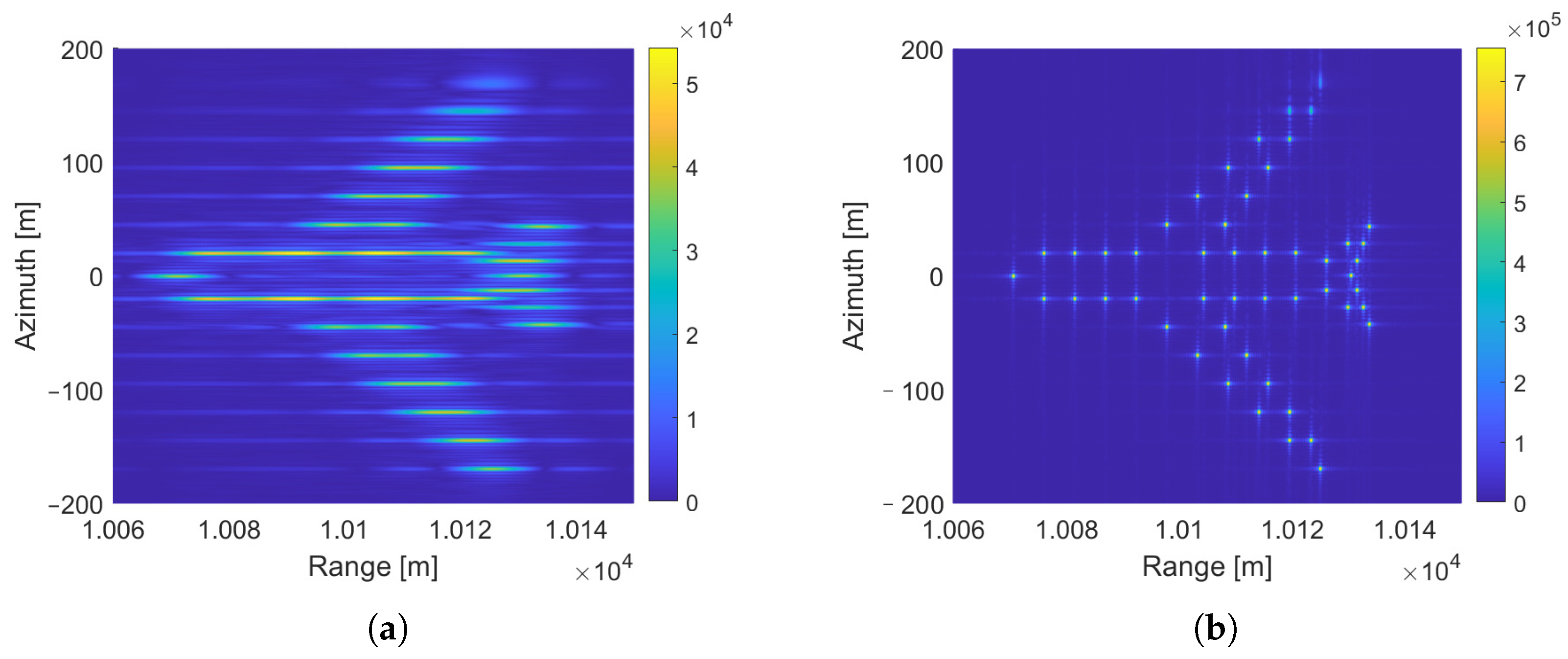
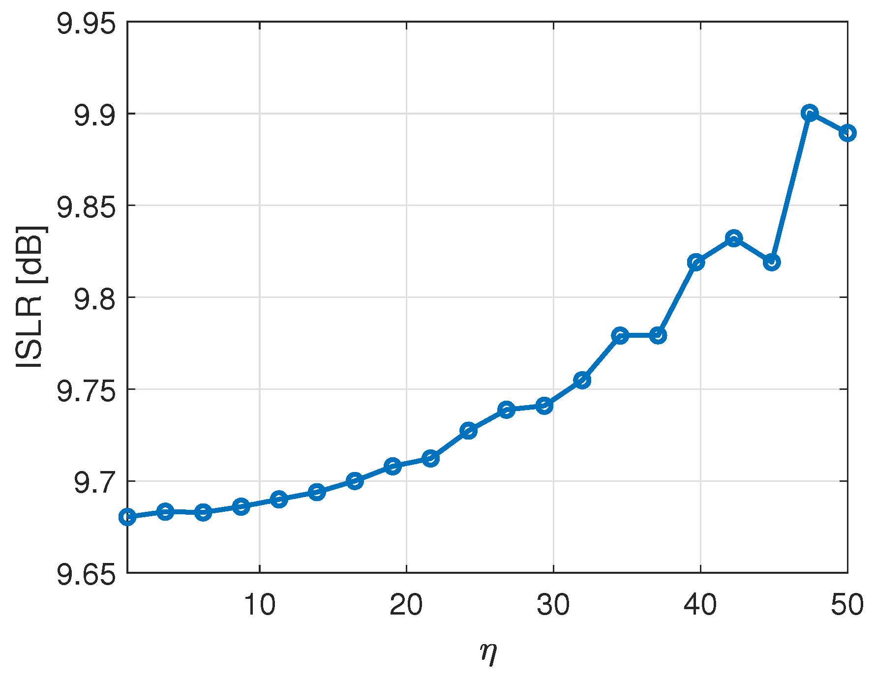
6.2. SAR Imaging Performance Analysis

To verify the imaging performance of the algorithm proposed in this paper, we conducted SAR imaging simulations using both the algorithm from reference [24] and the algorithm proposed in this paper for point target scenes.
Figure 8 shows the imaging results of point targets with different secondary compression algorithms. Figure 8a shows the imaging results obtained by using the secondary matched filtering algorithm in reference [24], and Figure 8b shows its range dimension profile. It can be seen that when the P point signal source transmitted narrowband radar signals, the bandwidth of the secondary signal modulated by the algorithm in reference [24] could not be greater than the received radar signals, which severely limited the range resolution. When the bandwidth of the P point transmission signal was 10 MHz, its range resolution was only 15 m. Figure 8c shows the point target imaging results using the algorithm designed in this study, and Figure 8d shows its range dimension profile. It can be seen that the signal designed in this study obtained a high resolution of the modulated 200 MHz large bandwidth signal in the range direction after the secondary compression, which was 0.75 m.
Figure 9 shows the imaging results of a multiple scattering points scene when different algorithms were used. Figure 9a shows the imaging results when the algorithm in reference [24] was used, and Figure 9b shows the imaging results when the algorithm in this paper was used. It can be seen that the algorithm in reference [24] no longer had the high resolution required for SAR imaging in the range direction when the NCR transmitted narrowband signals. However, the algorithm proposed in this paper could still obtain the high resolution of large bandwidth signals in the range direction, and the imaging results were relatively ideal.
PSLR [30] and ISLR [31] are important indicators for evaluating SAR imaging quality. Setting the bandwidth expansion factor η based on the NCR transmission signal bandwidth B and the secondary phase signal bandwidth B s gives
η = B s B
It can be seen from Section 2.2 that the bandwidth B s of the secondary phase signal was proportional to the number of false target retransmissions. Because of the retransmission interval τ = 1 / B , the modulation of the secondary phase signal was equivalent to η times of downsampling. When B was constant, the downsampling multiple increased with the increase in B s , which had an impact on the peak sidelobe ratio and integral sidelobe ratio of the sin c function after dechirping.
Figure 10 shows the relationship between the PSLR of the sin c function obtained by dechirp processing of the point target distance dimension and the variation in η . It can be seen that when η = 20 , that is, B s = 20 B , the PSLR of the range compression result could still be maintained above 13.2 dB, and the impact on the SAR imaging performance could be ignored.
Figure 11 shows the relationship between the ISLR of the sin c function with the change in η after the point target range dimension dechirp processing. It can be seen that when η = 20 , the ISLR was greater than 9.7 dB, which met the requirements of conventional SAR imaging. As η increased, the signal energy gradually concentrated on the main lobe, which caused the ISLR to show an upward trend.
From the above analysis, it can be seen that on the premise of ensuring the imaging performance, the joint signal bandwidth designed in this study could reach 20 times the intercepting signal bandwidth at most, that is, the range resolution performance compared with the algorithm in reference [24] could be improved by 20 times.

7. Conclusions

This paper proposes a design and processing method for a broadband SAR imaging signal based on a narrowband DFTJS, which can achieve high-range-dimension-resolution SAR imaging while jamming an NCR. By modulating a large bandwidth secondary phase signal on the narrowband DFTJS at each fixed forwarding interval, the echo signal is matched and filtered first, and then the secondary compression is performed by dechirp processing to obtain the SAR imaging results with a high range dimension resolution. At the same time, the modulated secondary phase signal will not affect the jamming effect.
Simulation experiments were designed and carried out to evaluate the jamming and imaging performance of the designed joint signal. The experimental results show that the designed signal could produce a jamming effect on the NCR, which made it unable to detect the real target. At the same time, using this signal for SAR imaging processing could obtain the imaging results of the range resolution corresponding to 20 times the bandwidth of the intercepted signal at most and achieve the high-resolution performance of broadband signals using narrowband jamming signals.
However, the research on secondary compression is still in its early stage. In order for the results after the first compression to have the characteristics of secondary compression, the false target forwarding interval must be fixed and cannot be changed, which makes it impossible to flexibly adjust the jamming effect. Future research may focus on the combination of more complex jamming signals and imaging signals, as well as explore applications in complex scenes, such as MIMO systems.

Author Contributions

Conceptualization, G.L. and Z.H.; Methodology, Z.H.; Software, H.P. and J.Z.; Validation, Z.H. and Q.Z.; Formal analysis, G.L. and H.P.; Investigation, H.P.; Resources, G.L. and Q.Z.; Data curation, G.L.; Writing – original draft, Z.H.; Writing – review & editing, H.P., Q.Z. and J.Z.; Supervision, Q.Z.; Project administration, G.L. All authors read and agreed to the published version of this manuscript.

Funding

This project is supported by National Natural Science Foundation of China No. 62306221.

Data Availability Statement

The data presented in this study are available upon request from the corresponding author.

Acknowledgments

The authors are thankful for the academic editor’s and reviewers’ comments on this work.

Conflicts of Interest

The authors declare no conflicts of interest.

References

  1. James, R.J. A history of radar. IEE Rev. 1989, 35, 343–349. [Google Scholar] [CrossRef]
  2. Guarnieri, M. The Early History of Radar [Historical]. IEEE Ind. Electron. Mag. 2010, 4, 36–42. [Google Scholar] [CrossRef]
  3. Yang, B.; Zhang, H. A CFAR algorithm based on Monte Carlo method for millimeter-wave radar road traffic target detection. Remote Sens. 2022, 14, 1779. [Google Scholar] [CrossRef]
  4. Sokol, Z.; Szturc, J.; Orellana-Alvear, J.; Popova, J.; Jurczyk, A.; Célleri, R. The role of weather radar in rainfall estimation and its application in meteorological and hydrological modelling—A review. Remote Sens. 2021, 13, 351. [Google Scholar] [CrossRef]
  5. Tagliaferri, D.; Rizzi, M.; Nicoli, M.; Tebaldini, S.; Russo, I.; Monti-Guarnieri, A.V.; Prati, C.M.; Spagnolini, U. Navigation-aided automotive SAR for high-resolution imaging of driving environments. IEEE Access 2021, 9, 35599–35615. [Google Scholar] [CrossRef]
  6. Piotrowsky, L.; Kueppers, S.; Jaeschke, T.; Pohl, N. Distance Measurement Using mmWave Radar: Micron Accuracy at Medium Range. IEEE Trans. Microw. Theory Tech. 2022, 70, 5259–5270. [Google Scholar] [CrossRef]
  7. Xu, Y.; Jin, T.; Chi, H.; Zheng, S.; Jin, X.; Zhang, X. Photonic generation of dual-chirp waveforms with improved time-bandwidth product. IEEE Photonics Technol. Lett. 2017, 29, 1253–1256. [Google Scholar] [CrossRef]
  8. Zhang, W.; Zhang, Q.; Zhang, T.; Zhao, Q.; Fu, S. Research on interference coupling mechanism and test method of UAV in complex electromagnetic environment. In Proceedings of the 2021 13th International Symposium on Antennas, Propagation and EM Theory (ISAPE), Zhuhai, China, 1–4 December 2021; pp. 01–03. [Google Scholar] [CrossRef]
  9. Li, X.; Chen, B. An Effective Composite Jamming Method for Synthetic Aperture Radar in Practical Electronic Countermeasures. In Proceedings of the 2024 IEEE International Conference on Acoustics, Speech, and Signal Processing Workshops (ICASSPW), Seoul, Republic of Korea, 14–19 April 2024; pp. 370–373. [Google Scholar] [CrossRef]
  10. Han, X.; He, H.; Zhang, Q.; Yang, L.; He, Y. Suppression of deception-false-target jamming for active/passive netted radar based on position error. IEEE Sens. J. 2022, 22, 7902–7912. [Google Scholar] [CrossRef]
  11. Liu, G.; Li, L.; Ming, F.; Sun, X.; Hong, J. A controllable suppression jamming method against SAR based on active radar transponder. Remote Sens. 2022, 14, 3949. [Google Scholar] [CrossRef]
  12. Shi, Y.; Huang, H.; Ma, Z. An Inter-Pulse Non-Coherent Jamming Technology Against SAR Based on Stepped Time-Delay. In Proceedings of the 2021 7th International Conference on Systems and Informatics (ICSAI), Chongqing, China, 13–15 November 2021; pp. 1–5. [Google Scholar] [CrossRef]
  13. Yang, K.; Ma, F.; Ran, D.; Ye, W.; Li, G. Fast generation of deceptive jamming signal against spaceborne SAR based on spatial frequency domain interpolation. IEEE Trans. Geosci. Remote Sens. 2021, 60, 1–15. [Google Scholar] [CrossRef]
  14. Zhou, Q.; Zhou, S.; Yang, L.; Ning, X.; Xing, M. Synthetic aperture radar interference based on scene fusion and active cancellation. IEEE J. Sel. Top. Appl. Earth Obs. Remote Sens. 2021, 14, 10375–10382. [Google Scholar] [CrossRef]
  15. Moreira, A.; Prats-Iraola, P.; Younis, M.; Krieger, G.; Hajnsek, I.; Papathanassiou, K.P. A tutorial on synthetic aperture radar. IEEE Geosci. Remote Sens. Mag. 2013, 1, 6–43. [Google Scholar] [CrossRef]
  16. Tsokas, A.; Rysz, M.; Pardalos, P.M.; Dipple, K. SAR data applications in earth observation: An overview. Expert Syst. Appl. 2022, 205, 117342. [Google Scholar] [CrossRef]
  17. Jawak, S.D.; Bidawe, T.G.; Luis, A.J. A review on applications of imaging synthetic aperture radar with a special focus on cryospheric studies. Adv. Remote Sens. 2015, 4, 163–175. [Google Scholar] [CrossRef]
  18. Demirci, S.; Izumi, Y. Application of H/ α ¯ Decomposition to Limited and Dual-Polarimetric 3D SAR Data of Civilian Vehicles. IEEE Access 2023, 11, 83589–83602. [Google Scholar] [CrossRef]
  19. Olsen, K.E.; Asen, W. Bridging the gap between civilian and military passive radar. IEEE Aerosp. Electron. Syst. Mag. 2017, 32, 4–12. [Google Scholar] [CrossRef]
  20. Almutiry, M. UAV tomographic synthetic aperture radar for landmine detection. Eng. Technol. Appl. Sci. Res. 2020, 10, 5933–5939. [Google Scholar] [CrossRef]
  21. Kaushal, H.; Kaddoum, G. Applications of lasers for tactical military operations. IEEE Access 2017, 5, 20736–20753. [Google Scholar] [CrossRef]
  22. Koo, V.; Chan, Y.K.; Vetharatnam, G.; Chua, M.Y.; Lim, C.H.; Lim, C.S.; Thum, C.; Lim, T.S.; bin Ahmad, Z.; Mahmood, K.A.; et al. A new unmanned aerial vehicle synthetic aperture radar for environmental monitoring. Prog. Electromagn. Res. 2012, 122, 245–268. [Google Scholar] [CrossRef]
  23. Liu, G.; Yang, W.; Wang, Y.; Bao, Y.; Wang, S.; Wu, H.; Li, P. MIMO FBMC-based joint radar imaging and electronic jamming. IEEE Geosci. Remote Sens. Lett. 2023, 20, 1–5. [Google Scholar] [CrossRef]
  24. Liu, G.; Zhang, Q.; Huang, Z.; Chen, T.; Mu, B.; Guo, H. SAR Imaging of Dense False Target Jamming Based on Phase Modulation. IEEE Geosci. Remote Sens. Lett. 2024, 22, 4000105. [Google Scholar] [CrossRef]
  25. Richards, M.A.; Scheer, J.; Holm, W.A.; Melvin, W.L. Principles of Modern Radar; SciTech Publishing: Raleigh, NC, USA, 2010. [Google Scholar]
  26. Yang, X.; Wen, G.; Ma, C.; Hui, B.; Ding, B.; Zhang, Y. CFAR detection of moving range-spread target in white Gaussian noise using waveform contrast. IEEE Geosci. Remote Sens. Lett. 2016, 13, 282–286. [Google Scholar] [CrossRef]
  27. Chen, X.; Su, N.; Huang, Y.; Guan, J. False-alarm-controllable radar detection for marine target based on multi features fusion via CNNs. IEEE Sensors J. 2021, 21, 9099–9111. [Google Scholar] [CrossRef]
  28. Vaidyanathan, P. Generalizations of the sampling theorem: Seven decades after Nyquist. IEEE Trans. Circuits Syst. Fundam. Theory Appl. 2001, 48, 1094–1109. [Google Scholar] [CrossRef]
  29. Zhu, D.; Zhu, Z. Range resampling in the polar format algorithm for spotlight SAR image formation using the chirp z-transform. IEEE Trans. Signal Process. 2007, 55, 1011–1023. [Google Scholar] [CrossRef]
  30. Letsch, K.; Berens, P. PSLR estimation for SAR systems with consideration of clutter background. In Proceedings of the SAR Image Analysis, Modeling, and Techniques VII. SPIE, Bruges, Belgium, 19–20 September 2005; Volume 5980, pp. 13–22. [Google Scholar] [CrossRef]
  31. Xu, Z.; Li, H.C.; Shi, Q.; Wang, H.; Wei, M.; Shi, J.; Shao, Y. Effect analysis and spectral weighting optimization of sidelobe reduction on SAR image understanding. IEEE J. Sel. Top. Appl. Earth Obs. Remote Sens. 2019, 12, 3434–3444. [Google Scholar] [CrossRef]
Figure 1. Application scenario of jamming and SAR imaging joint system.
Remotesensing 17 01196 g001
Figure 2. Secondary phase modulation method.
Remotesensing 17 01196 g002
Figure 3. The time–frequency structure of the signal received by P and the result of the PC.
Remotesensing 17 01196 g003
Figure 4. PC result when τ = 1 1 B B .
Remotesensing 17 01196 g004
Figure 5. Dechirp processing: (a) time–frequency diagram of echo signal and reference signal; (b) dechirp processing results of echo signal in (a).
Remotesensing 17 01196 g005
Figure 6. Detection results of P without jamming: (a) CFAR processing result of P; (b) local magnification result of (a).
Remotesensing 17 01196 g006
Figure 7. Jammed detection results of P: (a) CFAR processing result of P; (b) local magnification result of (a).
Remotesensing 17 01196 g007
Figure 8. SAR imaging results of point target: (a) imaging results using the algorithm in reference [24]; (b) range dimension profile of (a); (c) imaging results using the algorithm in this paper; (d) range dimension profile of (c).
Remotesensing 17 01196 g008
Figure 9. SAR imaging results of multiple scattering point targets: (a) imaging results using the algorithm in reference [24]; (b) imaging results using the algorithm in this paper.
Remotesensing 17 01196 g009
Figure 10. PSLR changing with η .
Remotesensing 17 01196 g010
Figure 11. ISLR changing with η .
Remotesensing 17 01196 g011
Table 1. Simulation parameter settings.
ParameterValue
Carrier frequency5 GHz
UAV velocity100 m/s
UAV altitude200 m
Central slant range10 km
Waveform bandwidth of P10 MHz
Pulse width of P10 us
Bandwidth of secondary phase signal200 MHz
Sampling rate400 MHz
SNR10 dB
Disclaimer/Publisher’s Note: The statements, opinions and data contained in all publications are solely those of the individual author(s) and contributor(s) and not of MDPI and/or the editor(s). MDPI and/or the editor(s) disclaim responsibility for any injury to people or property resulting from any ideas, methods, instructions or products referred to in the content.

