Abstract
The occurrence of surface strata movement in underground coal mining leads to the generation of numerous ground fissures, which not only damage the ecological environment but also disrupt building facilities, lead to airflow and easily trigger coal spontaneous combustion, induce geological disasters, posing a serious threat to people’s lives, property, and mining production. Therefore, it is particularly important to quickly and accurately obtain the information of ground fissures and then study their distribution patterns and the law of spatial-temporal evolution. The traditional field investigation methods for identifying fissures have low efficiency. The rapid development of UAVs has brought an opportunity to address this issue. However, it also poses new questions, such as how to interpret numerous fissures and the distribution law of fissures with underground mining. Taking a mine in the Shenfu coalfield on the semi-desert aeolian sand surface as the research area, this paper studies the fissure recognition from UAV images by deep learning, fissure development law, as well as the mutual feed of surface condition corresponding to the under-ground mining progress. The results show that the DRs-UNet deep learning method can identify more than 85% of the fissures; however, due to the influence of seasonal vegetation changes and different fissure development stages, the continuity and integrity of fissure recognition methods need to be improved. Four fissure distribution patterns were found. In open-cut areas, arc-shaped fissures are frequently observed, displaying significant dimensions in terms of depth, length, and width. Within subsidence basins, central collapse areas exhibit fissures that form perpendicular to the direction of the working face. Along roadways, parallel or oblique fissures tend to develop at specific angles. In regions characterized by weak roof strata and depressed basins, abnormal reverse-“C”-shaped fissures emerge along the mining direction. The research results comprehensively demonstrate the process of automatically identifying ground fissures from UAV images as well as the spatial distribution patterns of fissures, which can provide technical support for the prediction of ground fissures, monitoring of geological hazards in mining areas, control of land environmental damage, and land ecological restoration. In the future, it is suggested that this method be applied to different mining areas and geotechnical contexts to enhance its applicability and effectiveness.
1. Introduction
The increasingly prominent environmental degradation caused by mining has become a pressing issue. Underground coal mining induces changes in the stress of rock and soil masses, resulting in overlying rock failures and loose soil deformation, leading to non-uniform surface subsidence and the formation of mining-induced ground fissures [1]. Ground fissures pose a significant risk to various engineering structures, including buildings, underground pipelines, transportation routes, and embankments, by causing deformation and damage [2,3]. They are one of the main causes of landslides in mining areas [4,5], diverting airflow, leading to spontaneous combustion of underground coal and even coalfield fires, resulting in the wastage of coal resources and threatening coal mine safety [6]. In terms of ecological environment, they cause mechanical damage to plant root systems and vegetation degradation [7], reduce soil quality, and exacerbate soil erosion, especially in ecologically fragile arid and semi-arid areas in the western region [8,9]. These adverse effects not only endanger the lives and property of local residents but also pose significant challenges to the sustainable development of coal mining areas. Effective monitoring and early warning of ground fissures play a critical role in ensuring coal mine safety and advancing the development of environmentally friendly mining practices [10].
The traditional monitoring methods, such as manual field investigation, total station, GPS, and so on, are time-consuming, laborious, and easily affected by human subjectivity. It is difficult to obtain real-time, efficient, systematic, and comprehensive information on surface rock displacement and distribution of ground fissures [3,11,12].
According to the previous observation data of mining ground fissures, the width of ground fissures is usually in centimeters to sub-meters level [2,13]. Therefore, the resolution of optical satellite images is not suitable for mining-induced ground fissures. Uncrewed Aerial Systems (UAVs) provide the benefits of enhanced spatial resolution, lightweight, fast speed, terrain independence, and flexible acquisition of centimeter-level images, which can provide an ideal data source for dynamic monitoring [14,15,16]. UAVs have been extensively employed in various studies related to surface deformation, with numerous applications such as landslide detection [17], water resource management, and monitoring [18]. Particularly, the potential applications of UAVs in the mining industry are boosting [19]. For example, UAVs are increasingly being used to identify ground fissures induced by coal mining with increasing efficiency and accuracy [20,21].
Although the high resolution and full coverage of UAV aerial ‘big data’ means that all ground fissures can be obtained, identifying and extracting numerous ground fissures quickly from UAV images is still a challenging task. Since the ground fissure of a goaf area, whether in a natural environment or an abandoned human activity area, the information collected by the UAVs is extremely complex, containing noise information that is identical to the ground fissures. This noise information can seriously affect the performance of the automatic extraction of ground fissures [22].
In order to validate the feasibility of rapid identification methods for detecting ground fissures based on UAVs imagery and minimize interference from noise sources such as vegetation coverage, we selected the SGT mine in the Shenfu Coal Fiel, which is located in a semi-desert aellian sand area and serves as one of the largest coal reserves in the world, for a case study. Additionally, another objective of this paper is to develop a fast and accurate automatic identification method for detecting ground in a specific mining area and then bridging the distribution pattern of these fissures with coal mining. To achieve these goals, based on the study of its fissure characteristics [1,23], the UAV aerophotography scheme matching the scale of ground fissure field investigation was designed, and an automatic identification method based on deep learning was developed to realize the identification and extraction of fissures with high efficiency. The comparison verification and effect evaluation are carried out using the visual interpretation method, and corresponding analysis is adopted in combination with the underground mining progress, revealing the distribution rules of ground fissure development and the response to underground mining conditions. Finally, the mining fissure development models in the study area under different working conditions are summarized. The aim of this study is to rapidly, accurately, and automatically identify ground fissures caused by coal mining, understand the distribution patterns of fissures, and provide technical support for monitoring and protecting against geological hazards, as well as for ecological conservation and restoration in mining areas.
2. Study Area
The SGT coal mine lies at Daliuta Town, Shenmu County, Shaanxi Province, which is in the northeast of the Shendong mining area. It is located in the northern part of the Loess Plateau in northern Shaanxi and on the southeastern margin of the Mu Us Desert. The geomorphic units in the mining area can be divided into two categories: the aeolian sand area is in the north of the minefield, and the loess hilly and gully region is in the south of the minefield (Figure 1). The terrain is high in the east and low in the west. The highest point is located in eastern Fengtailiang, at an elevation of 1351 m. The lowest point is located in the valley of the Wulanmulun River, with an elevation of 1122 m. The terrain exhibits a relative height difference of 229 m and a general elevation of 1250 m. It is about 8.4 km long from north to south, 8.5 km wide from east to west, and covers an area of about 60 km2. This region has a semi-arid continental monsoon climate in the north temperate zone and is a semi-desert area covered by a large area of wavy dunes. The ground vegetation is sparse, mainly for small poplar trees, sand willow trees, and wild drought-resistant weeds, which are planted to resist sandstorms. The bedrock occurs sporadically in the study coal mine area, mostly covered by the Quaternary sediment, and the average thickness of the loose layer is about 8 m (Figure 2). The coal-bearing strata in the coal mine is a part of a Jurassic coalfield in northern Shaanxi Province. The geological structure is simple, inclined to the southwest, and the stratum is gentle, with an overall inclination of less than 3°, nearly horizontal, and a monoclinic structure tilted to the west, with no large or medium-sized faults. The surrounding rock of the laneway belongs to sedimentary stratified clastic rock. The lithology is mainly mudstone and sandstone sedimentary rock with a medium-thick and thin-layered structure, and the rock’s mechanical strength varies greatly.
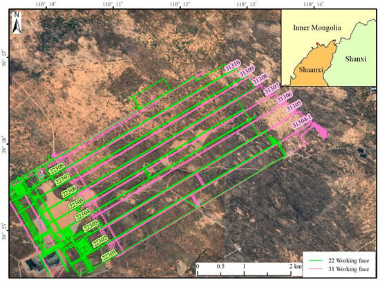
Figure 1.
The study area, the mining area, and the distribution of working faces. The background RS image illustrates the semi-desert aeolian sand environment.
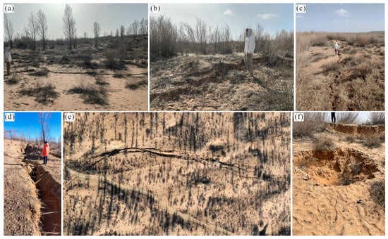
Figure 2.
Geological and geographic characteristics of the SGT mining area and mining-induced ground fissures captured by field investigations. (a) Vegetation and geomorphology, ground fissures above the laneway at the edge of the working face parallel to the direction of mining; (b) Ground fissures in the central subsidence area of the working face perpendicular to the direction of mining; (c) Ground fissures above the laneway at the edge of the face parallel to the direction of mining; (d) Scene photos of deep and large fissures in the open-cutting; (e) Aerial view photos of deep and large fissures in the open-cutting with drones; (f) Collapse pit and step large fissures in the center deformation area above the working face.
The long wall mining method is utilized for coal mining, and the fully caving method is adopted for roof management. The occurrence of coal-bearing strata varies a little along the strike and dip and is close to horizontal. At present, the main coal seams are No. 22 coal seam and No. 31 coal seam. The average buried depth of the No. 22 coal seam is about 97 m, the thickness ranges from 1 to 6 m, the thickness of the coal seam is obviously different, and it belongs to the stable type of medium-thick coal seam. No. 31 coal seam, with an average buried depth of about 134 m and a thickness of 2~4 m, has a simple structure and can be classified as a stable type of thick coal seam (Figure 3).
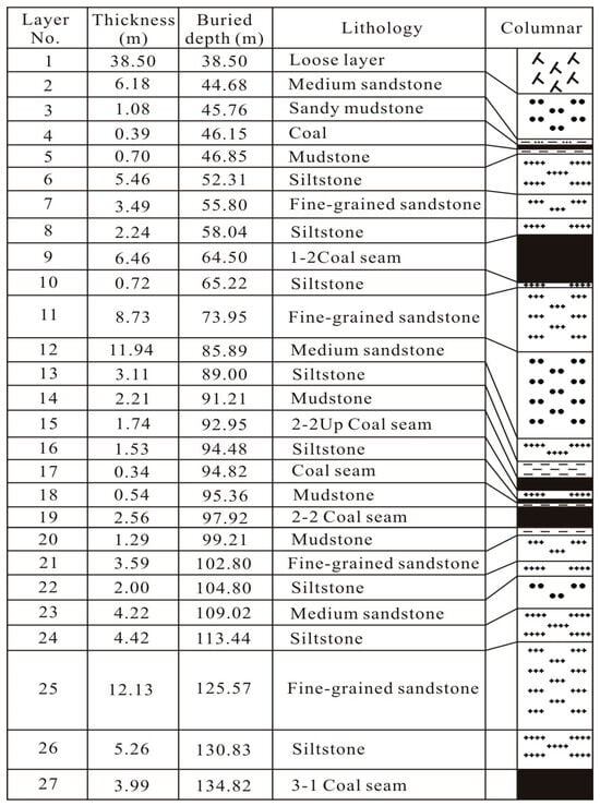
Figure 3.
Borehole histogram of the No. 22304 working face in the SGT mine.
3. Automatic Fissures Recognition from Aerial Images
3.1. Overall Process of Automatic Fissure Identification in UAV Flight Images
The deep learning method for automatic interpretation of ground fissures is completed in six steps (Figure 4).
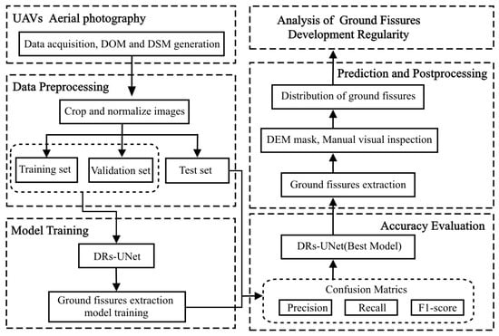
Figure 4.
A flowchart of automatic extraction of ground fissures from UAV images.
(1) UAVs aerial photography: Drone flight, using the DJI M300RTK equipped with ZenmuseP1 lens to shoot, then DJI Terra software is used for mission planning and raw data processing. Images collected by the UAVs were spliced to generate a 3-cm-resolution digital orthophoto map (DOM) and a 10-cm-resolution digital surface model (DSM) in the study area. The aerial photography covers an area of 4 km2 for 2 to 3 h at a time, which can fully cover the monthly mining progress and trace the mining subsidence area for half a year. The resolution of 3 to 5 cm can reach the scale of in-situ fissure investigation in the experimental area. For details, see the product’s official website (https://www.dji.com/cn, accessed on 8 January 2024).
(2) Data preprocessing: Using the visual interpretation method to label mining ground fissures in the DOM image of UAV aerial photography. Then, the labeled data is clipped into image patches, normalized, and further segmented into three data sets: training, validation, and testing.
(3) Model Training: In order to extract ground fissures, DRs-UNet was used to construct and train the model.
(4) Accuracy evaluation: Quantitative evaluation of the trained model by accuracy, recall rate, F1-score, and Intersection over Union (IoU).
(5) Prediction and postprocessing: The trained DRs-UNet model is used to identify and extract ground fissures in mining areas, and artificial visual inspection is carried out on the extracted ground fissures to remove misclassified information such as trees, weeds, and their shadows, optimize the identification results, and obtain the real ground fissure distribution information.
(6) Analysis of ground fissures development regularity: Finally, the spatiotemporal pattern of the mining ground fissures is investigated.
Here, we briefly summarized the workflow for the construction of the sample dataset. After obtaining the DOM from UAV photogrammetry, manual visual interpretation was conducted in the study area to identify and map the locations of active ground fissures. Based on this information, an image dataset required for training deep learning models was created. Firstly, using Environmental Systems Research Institute (ESRI) ArcGIS software, the active ground fissures were manually interpreted and outlined on the UAVs-derived DOM image, resulting in a binary mask of the fissures. Due to the computer’s memory limitation, the sample size inputted into the deep learning model cannot be too large, requiring the images to be discretized into smaller patches. Additionally, as the performance of the deep learning model is closely related to the size of the training dataset [24], following the strategy proposed by a prior study [25], each dataset in this study was discretized with a 50% overlap with the nearby dataset to expand the dataset. The data was sliced with a sliding window approach, resulting in 1712 images of size 128 × 128 pixels. Subsequently, the samples were standardized using the Z-Score method, ensuring that the average pixel value of each sample is 0 and the variance is 1. This step aims to facilitate a smoother and easier training process. Finally, the samples were divided into training set, validation set, and testing set in a ratio of 7:2:1. The training set was used to train the model, the validation set was utilized to select the best model parameters during the training iterations, and the testing set was used to quantify the performance of the model.
3.2. The Methodology of the Deep Residual Shrinkage U-Net (DRs-UNet)
In recent years, there has been a rapid development in semantic segmentation [26,27]. Deep learning semantic segmentation networks with an encoder-decoder structure have shown superiority over Fully Convolutional Networks (FCN) in considering global contextual information. The encoder extracts potential high-level and abstract semantic features from the original input image, while the decoder performs pixel-level predictions based on the features extracted by the encoder [28]. U-Net and ResNet, commonly used for crack detection, belong to this type of architecture and are known for their ease of training and high robustness [24,29]. The name U-Net originates from its U-shaped symmetrical encoding design structure, which offers architectural simplicity and high flexibility [30].
Deep Residual Shrinkage Network (DRSN) is a variant of ResNet, initially proposed by Zhao et al. [31] for fault diagnosis in mechanical transmission systems. ResNet, which is composed of a stack of residual modules, overcomes the challenge of vanishing gradients that occurs with traditional convolutional neural networks as the network deepens by using shortcut connections [29]. Assuming the input features of a residual module are denoted as xl and the output features of the residual branch as F(xl), the final output is the sum of the residual branch and the identity shortcut branch (element-wise addition): F(x) + xl. The forward propagation process of the data is as follows:
where, wl represents the weight parameters, and F(x,wl) denotes the residual mapping that the network needs to learn.
Although ResNet can effectively address the problem of network degradation, the model’s learning capability significantly decreases when dealing with signals that have high levels of noise [32]. Soft thresholding is a fundamental step in many traditional denoising methods. It sets features that are below a certain threshold to zero and adjusts other features to be close to zero, thereby attenuating noise below a specific threshold [31]. The soft thresholding expression can be defined using the following equation:
In Equation (2), y represents the output features, x indicates the input features, and τ denotes the threshold. Therefore, by embedding the soft thresholding within the residual block and utilizing the soft thresholding method to filter the features (Equation (2)), noise and redundant information can be suppressed. Through backward gradient propagation, the threshold can be automatically updated. The gradient computation expression for soft thresholding is given by Equation (3):
The DRs-UNet (Deep Residual Shrinkage U-Net) is a convolutional encoder-decoder network that combines the U-Net and ResNet models’ structures with the soft thresholding method. It enables end-to-end extraction of geological faults. This design not only effectively prevents the problem of gradient vanishing caused by deepening convolutional neural networks but also accelerates model training and convergence. Additionally, it reduces noise in the input signals, reduces redundancy in the features, and improves the classification accuracy of the images. The DRs-UNet consists of an encoder and a decoder. The encoder performs downsampling and feature extraction through convolutional operations, resulting in a series of feature maps. The decoder then restores the resolution of the feature maps, ultimately obtaining the position and extent of the active ground fissures (Figure 5).
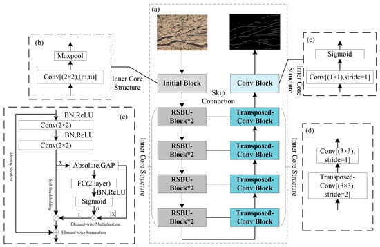
Figure 5.
Schematic of the DRs-UNet deep learning method of fissure. (a) The overall structure of DRs-UNet; (b) The interior structure of the initial block; (c) The interior structure of the residual shrinkage building unit block (RSBU-Block); (d) The interior structure of the transposed convolution block; (e) The interior structure of the final convolution block.
3.3. Evaluation of Ground Fissure Identifications
The experiments were conducted on a computer equipped with an Intel Core i7-11800H CPU (2.30 GHz) and an NVIDIA GeForce RTX 3060. PyTorch (GPU version) was utilized as the deep learning framework in this article. For efficient GPU parallel computation and acceleration, CUDA 11.0 and CuDNN 8.2 were chosen. The parameters were updated and optimized using the Adam optimizer.
Table 1 presents the confusion matrix for the binary classification task in this paper. True positives (TP) represent correctly classified ground fissure targets. True negatives (TN) indicate accurate predictions of non-fissure targets by the model. False positives (FP) refer to non-fissure targets that are incorrectly predicted as fissures. False negatives (FN) signify the fissure targets that are mistakenly classified by the model.

Table 1.
Confusion matrix for ground fissures extraction task.
In this study, the results of visual interpretation and on-site investigation were used as the ground truth for verification. Confusion matrices were established by comparing the extracted results of automatic fissure identification with the ground truth (Table 1) [22,33,34,35]. Common quantitative evaluation metrics such as Precision, Recall, and F1-score were employed to assess the performance of the model [32]. Precision represents the proportion of correctly predicted fissures out of all predicted fissures results. Recall represents the proportion of correctly predicted fissures out of all true fissures. F1-score is the harmonic mean of Precision and Recall, providing a more balanced metric.
3.4. Result of Ground Fissure Identifications
The expressions for Precision, Recall, and F1-score were calculated as 86.07%, 86.12%, and 86.08%, respectively. Compared to previous automatic identification results in fields such as highways and mining operations [22,35,36,37], considering the semi-desert wind-blown sand background of the study area, the automatic model and application in this study achieved satisfactory recognition results.
4. Fissures Distribution Patterns
4.1. Introduction to the Working Methods of Fully Mechanized Coal Mining
The adoption of the directional longwall mining method and the full caving method for roof management in mining areas has a direct impact on surface deformation and damage. The directional longwall mining method leads to relatively uniform roof failure, resulting in continuous, large-scale bending and sinking of the surface, with noticeable movement patterns. The full caving method for roof management leads to the most extensive roof failure, causing the most intense movement of rock layers and the surface, resulting in the largest deformation of the surface. Studies have shown that in mining areas with a certain thickness, the geological mining factors that predominantly influence the distribution of surface movement and deformation are the coal seam dip angle, the dimensions of the mining area, the depth of mining, the soil properties, the burial depth of the coal seam, and the thickness of the bedrock [38,39,40].
In this study, we focus on the 31,307–31,310 (22,308) working faces, in which the elevation of the ground surface ranges from 1251.5 m to 1286.55 m. The working face width is typically controlled between 260 m and 270 m, and the advancing length depends on the occurrence conditions of the coal seam, usually ranging from 4000 m to 4500 m. After the previous extraction of No. 12 coal seam (caved in 2008–2009) and No. 22 coal seam (caved in 2020–2021) within the area of interest, the current mining operations are focused on No. 22 coal seam and No. 31 coal seam. The No. 22 coal seam is generally mined 2–3 years earlier than the No. 31 coal seam.
The observed ground fissures in this study are primarily caused by the mining of No. 22 coal seam and No. 31 coal seam. The thickness of No. 22 coal seam ranges from 1.01 m to 2.62 m, with an average thickness of approximately 2 m. It is buried at a depth of 85–100 m and is considered a stable coal seam. The direct roof lithology of No. 22 coal seam is mudstone, occasionally with silt and fine sandstone. It lacks well-developed bedding and remains stable when encountering water. Its uniaxial compressive strength ranges from 15 to 30 MPa. The thickness of the immediate roof is between 2–15.8 m, generally averaging 2–8 m, with an average of 4.5 m. The thickness of the No. 31 coal seam ranges from 3.38 m to 4.05 m, with an average thickness of approximately 3.8 m. It is buried at a depth of 121–135 m and is also considered a stable coal seam. The direct roof lithology of the No. 31 coal seam is mainly composed of silt and fine sandstone, often occurring interbedded. In the northwest corner of the mining area, the thickness is greater, while in other areas, it is less than 6 m, averaging 4.2 m. It remains stable when encountering water, with a uniaxial compressive strength of 15–30 MPa. The attitude and inclination of the coal-bearing strata have little variation along the strike and dip, with a nearly horizontal attitude.
4.2. Spatial Distribution Pattern of Ground Fissures
The images captured by UAV flights during the period of 2022–2023 recorded the surface fissure information during the advancement of the working faces of No. 22 and No. 31 coal seams. Based on the interpretation results in the previous section, internal fissures tend to heal with the movement of the rock basin. However, permanent “O”-shaped static fissures often form along the edges of goaf openings and above the boundaries of laneways. This pattern is consistent with previous studies [1,3,13,41,42]. By further incorporating mining conditions and progress information, four categories of spatial distribution patterns for fissures can be classified.
4.2.1. The Open-Cut Ground Fissures
The ground fissures along the “permanent boundary” near the open cuts are characterized by their impressive size—they are the widest, longest, and deepest. The mining boundary on one side of the working face continuously moves forward with the advancement of the working face and is commonly referred to as the “dynamic boundary.” On the other hand, the goaf opening of the working face represents a fixed and unmoving boundary known as the “permanent boundary” [11,13,40,43]. Surface fissures at the open cut are located behind the advancing coal seam and experience prolonged tensile stress, resulting in significant fissure development with characteristics of width, depth, and length. Taking the fissures at the open-cut of the No. 31309 and No. 22307 working faces and fully mechanized mining faces as examples, an analysis is conducted on the characteristics of “permanent boundary” fissures and the surface movement patterns at the open-cut.
According to the operational data, the mining of the No. 22307 fully mechanized mining face at the No. 22 coal seam began in April 2019, with a depth of approximately 100 m. In September 2022, mining of the 31,309 fully mechanized mining face at the deeper 31 coal seam started, with a depth of approximately 135 m. UAV aerial photographs indicate that on 10 April 2022, there were no apparent fissures at the opencut of the No. 22307 working face. However, as of 22 December 2022, noticeable fissures near the opencut of the No. 31309 working face have developed parallel to the permanent boundary. These fissures are characterized by their significant width, length, and depth. The width of the fissures ranged from 40–60 cm, with the largest fissure length measuring approximately 250 m (measured along the arc length). The average spacing between fissures was around 2–5 m, with an interval of approximately 7–15 m between the innermost and outermost fissures of a group. These fissures exhibited the maximum dimensions in terms of width, length, and depth among all fissures in the entire mining area (see Figure 6 and Figure 7).
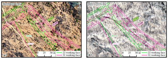
Figure 6.
Variation of ground fissures along the “permanent boundary” near the open-cut of the No. 22307 and 31309 fully mechanized mining faces (10 April 2022, 22 December 2022 UAVs aerial photography). (a) No significant fissures are observed at the open-cut during the mining of the coal seam 22; (b) During the mining of the No. 31 coal seam, massive fissures develop at the open-cut.
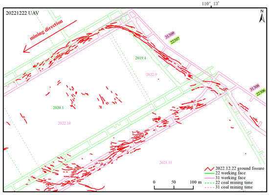
Figure 7.
The distribution of ground fissures developed at the open-cut near the No. 31309 and No. 22307 working faces on 22 December 2022.
After the extraction of the underlying ore body, the surrounding rock mass in the goaf area undergoes bending deformation, and the overlying strata fracture, fragment, and collapse. As the area of the goaf increases, the movement and deformation of the overlying strata propagate to the surface. This process manifests as cracks formed from rock layer breakage continuously expanding upwards within the rock strata [44]. According to the vertical development and distribution characteristics of mining-induced fractures, three continuous distinct zones are delineated above the goaf: caving zone, fractured zone, and sagging zone [45,46,47]. The force state changes at various points in the topsoil cause non-uniform subsidence and deformation at different points on the surface. When the stress on the topsoil layer exceeds its ultimate strength, the soil undergoes discontinuous failure along existing fractures, forming ground fissures (Figure 8).
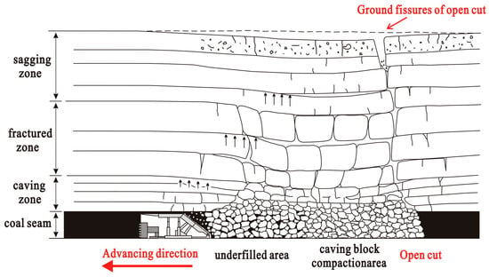
Figure 8.
A schematic diagram of the moving zones of overlying strata in longwall mining, especially showing why ground fissures of open-cut are deep and wide, modified from previous studies [45,46,47].
The surface subsidence and stretching deformation at the permanent boundary of the mining area are significantly greater than those at the dynamic boundary. In other words, the overlying strata and surface damage at the mining boundary are more severe than in the subsided basin. Throughout the mining process, the permanent boundary remains in the stretching deformation zone, while the dynamic boundary transitions from stretching deformation to compression deformation as the working face advances. Therefore, ground fissures are well-developed at the permanent boundary (Figure 8), making it a key area for ground fissure prevention and building protection.
4.2.2. The Ground Fissures Developed at the Central Collapse Zone near the Working Face
As the working face advances, the fracturing of the overlying strata above the underground goaf leads to surface collapse. Consequently, ground fissures form perpendicular to the direction of the working face’s strike. Moreover, along the edges of the subsided basin, above the laneway on both sides of the working face, fissures that are parallel to or oblique with an angle of 0–30° to the laneway may develop. The No. 31307 working face has a width of 255 m and a length of approximately 4675 m, with a mining height of about 3.7–3.9 m. At the location depicted in the diagram, the loose layer thickness ranges from 54.46 m to 62.34 m. Additionally, at the intersection between the No. 31307 and No. 31308 working faces, the bottom of the loose layer contains a 12.37-m-thick layer of silty clay. In the No. 31 coal seam, the No. 31307 working face is located to the south of the No. 30306 face and to the north of the No. 31308 working face. The No. 31306 working face, shown in the diagram, was mined in September 2020. The No. 31307 working face, depicted in the diagram, was mined in July–August 2021, while the No. 31308 working face, shown in the diagram, was mined between May and July 2022. The No. 22305 working face in the No. 22 coal seam was mined in 2016, and its northern adjacent face, the No. 22306 working face, was mined between January and May 2019 (Figure 9).
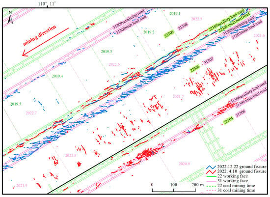
Figure 9.
Collapse-type ground fissures are perpendicular to the mining direction in the center of working faces and quasi-parallel ground fissures above the laneways.
The main characteristics of the ground fissures within the central collapse zone, which develop along a direction that is perpendicular to the strike of the working face, are as follows: The surface in the middle of the working face is within a curved subsidence zone. Here, collapse-induced fissures, in the form of elongated and intermittent fissures, develop along the central line of the working face, perpendicular to the laneway (the direction of the working face). The spacing between the fissures ranges from 2–10 m (relatively wide), with lengths of 30–50 m (Figure 9 and Figure 10). These fissures exhibit dynamic changes. As the working face advances, new fissures progressively parallel form, increase in length, expand forward, stabilize, or heal, closely related to the underground mining progress. The fissures have self-healing capabilities and may exhibit varying degrees of recovery or healing over time. Previous studies have shown that such fissures are mostly close due to surface compression deformation caused by the advancement of the working face, demonstrating dynamic changes [2,11,48].
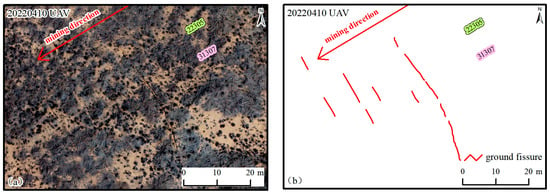
Figure 10.
UAV image on 10 April 2022, revealing the ground fissures induced by the central collapse in the working face (dynamic fissures perpendicular to the direction of the working face). (a) Fissures feature in UAVs image; (b) Identified fissures.
4.2.3. The Parallel and Oblique Ground Fissures above the Roadway
Two types of fissures primarily develop above the tunnel, parallel or at a small angle to the roadway.
The first type of fissure is developing parallel or nearly parallel to the mining direction. Take the ground fissures observed during the mining of the No. 31307 and 31308 working faces as an example. On 10 April 2022, when aerial photography was conducted, the northern side of the No. 31308 working face adjacent to the No. 31307 working face was not mined, while the southern side, the No. 31306 working face, had completed mining. The No. 31307 working face of the No.31 coal seam was mined between June and September 2021 at the corresponding position where the overlying No.22 coal seam (i.e., the No. 22305 working face) was mined in 2016. Above the northern boundary of the No. 31307 working face, beyond the adjoining historical laneway (at the 22,305 main and auxiliary haul road), parallel fissures aligned with the mining direction appeared (Figure 9 and Figure 11). Near the southern side of the No. 31307 working face (at the 31,306 main and auxiliary haul road), fissures that were approximately parallel to the mining direction (at an angle of 10°) appeared above the tunnel (Figure 9 and Figure 11). These fissures were relatively thin and narrow, occurring in a loose layer with a thickness of approximately 13.2 m.
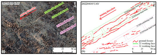
Figure 11.
Ground fissures approximating parallel to the mining direction above the laneway (UAVs Image on April 10, 2022). (a) Fissures feature in the UAVs image; (b) Identified fissures.
The second type of fissure develops obliquely to the mining direction with an angle of 20–30°. On 22 December 2022, when aerial photography was conducted, the No. 31308 working face at the indicated location had been mined between May and July 2022. The northern side remained unmined, while the southern side, the No. 31307 working face, had completed mining. A few parallel fissures have appeared on the north side of the No. 31308 working face’s laneway, where the loose layer has a thickness of approximately 7.8 m. Above the south side of the No. 31308 working face (at 31308 ventilating road and 31307 main haul road), a series of parallel fissures arranged at an angle of 20°–30° to the mining direction developed in an echelon pattern. These fissures were regular, fine, dense, narrow, and short, with an average spacing of approximately 3–7 m. The innermost and outermost fissures were separated by approximately 20–30 m. In this area, the loose layer was thicker, ranging from 43.9 to 62.45 m, with a 12.37-m-deep silty clayey silt layer at the bottom (Figure 9 and Figure 12).
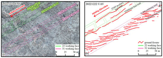
Figure 12.
Ground fissures developing obliquely at an angle of 20–30° to the mining direction above the laneway (UAVs Image on 22 December 2022). (a) Fissures feature in UAVs image; (b) Identified fissures.
The No. 31307 and No. 31308 working faces adopted the conventional high mining height (3.7–3.9 m) longwall mining method. After the main key layer ruptures either completely or partially, the overlying rock strata above the caved goaf continuously exhibit subsidence. The surface above the middle part of the working face was located within the curved subsidence zone, while the upper parts of the tunnels on both sides were positioned along the edges of the curved subsidence zone. Adjacent to the collapsed working face that had been previously mined, the upper part of the tunnel was situated in the tension-shear zone, making it prone to the development of parallel shear fissures at a certain angle (e.g., 20–30°) to the mining direction. These fissures were fine, dense, narrow, and short. On the other side, above the tunnel adjacent to the unmined working face, the fissures were positioned in the extension zone along the edge of the straight subsidence zone, making it susceptible to the development of fissures parallel to the tunnel. These fissures were wider, deeper, and longer. In the region where the loose layer was thicker (43.9–62.45 m), there was a higher density and regularity of fissure development with a relatively uniform distribution. In the region where the loose layer was thinner (7.8–13.2 m), there were fewer fissures, and the regularity was slightly lower, exhibiting clustered distribution patterns.
4.2.4. The Reverse-“C”-Shaped Ground Fissures within the Weak Overburden Zone
Typically, ground fissures along the edge of goaf exhibit an “O” shaped distribution. However, in terms of local sections of the advancing working face, surface fissures develop in a “C” shape directionally toward the mining advancement. The 22308 working face displays significant reverse “C” shaped fissures in the direction of mining advancement. The reasons for this abnormal phenomenon are as follows: (1) The DSM data derived from UAVs indicates that this area is a low-lying basin (refer to Figure 13). (2) The No. Upper-22 303 working face located at the No. The upper-22 coal seam (with a burial depth of 82.09 m), which is above the No. 22 coal seam, was previously mined in this area from July to November 2020. The No. 22308 working face of the No. 22 coal seam (with a burial depth of 92.64 m) underwent secondary repeated mining activities in the nearby vicinity between March and April 2023, causing further movement in the overlying rock layers.
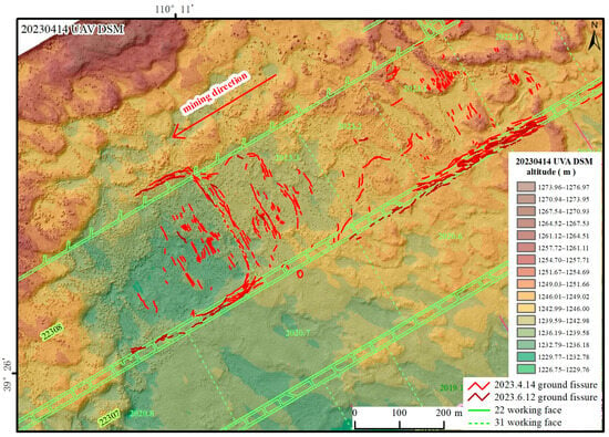
Figure 13.
Ground fissures and DSM extracted of UAVs image on 14 April 2023.
The No. Upper-22 coal seam here is approximately 10 m above the No. 22 coal seam. After the completion of mining activities in No. 22303, the working face of the overlying No. In the Upper-22 coal seam from July to November 2020, subsidence occurred. As the underlying No. 222308 working face approached the stress concentration zone of the underground goaf of the No. Upper-22 coal seam, advanced abutment pressure in the No. 22308 working face increased. Consequently, the stress environment in this area became complex.
The subsidence of the roof increases continuously due to the influence of repeated mining, and as the plastic zones of the roof of the No. 22 coal seam connect with the plastic zones of the overlying No. Upper-22 coal seam, the roof undergoes extensive deformation and damage. The significant abnormal reverse “C” shaped fissures observed during the mining activities in No. 22308 working face from March to April 2023 are attributed to the combined effect of the tension generated by the subsidence in the low-lying basin caused by the mining of the No. Upper-22 working face from July to October 2020. Therefore, the occurrence of abnormal reverse “C”-shaped fissures in the direction of mining should attract our attention, as it indicates the presence of low-lying basins or underground rock movements and deformations caused by secondary mining activities.
There are two funnel-shaped collapse pits with diameters of approximately 3.5 m (Figure 14). According to the drilling data obtained 200 m away from these collapse pits, the loose layer thickness is approximately 10 m, with the surface mainly composed of aeolian sand. Previous studies have shown that when the overlying strata consist of extremely soft or loose layers, funnel-shaped collapse pits are prone to occur on the surface. This situation is particularly common during shallow mining of thick coal seams [49].
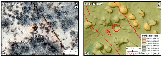
Figure 14.
Aerial map of the funnel-shaped collapse pit and topographic images on the west side of the No. 22308 working face (UAVs Image on 14 April 2023). (a) Features in UAVs image; (b) Identified fissures and collapse pit.
4.3. Classification and Comparison of Ground Fissure Development Patterns
The development of ground fissures in fully mechanized mining faces follows a distinct pattern. Initially, the distribution of ground fissures takes on an elliptical shape with the long axis parallel to the open cut. As the working face advances, the surface fissures develop in a “C” shape towards the direction of advancement. Along the edge of the goaf, permanent “O” shaped fissures form in the inner arc surrounding the rock movement basin. The research conducted in this mining area reveals more distinctive distribution patterns (refer to Figure 15 and Table 2).
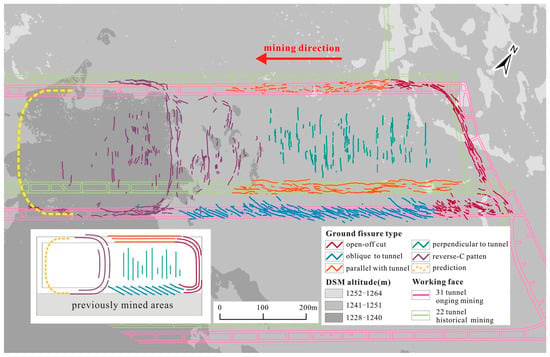
Figure 15.
Spatial distribution pattern of ground fissures development caused by multiple coal mining activities.

Table 2.
Comparison of characteristics of various ground fissures induced by coal mining.
The permanent boundary at the open-cut remains in a zone of tensile deformation, exhibiting the widest, longest, and deepest fissures. This area is of utmost importance for surface fissure prevention and the protection of building structures.
Within the subsidence basin, there is a distribution of central collapse areas where fissures develop perpendicular to the direction of the working face. These ground fissures appear as narrow, discontinuous, straight lines. As the dynamic boundary transitions from a state of tension to compression with the advancement of the working face, the ground fissures generally naturally heal after mining activities cease.
The area above laneways is prone to easily developing parallel or oblique at certain angles to the laneway. On the side adjacent to a collapsed working face, the laneway is situated in a shear-tension zone, making it susceptible to the formation of parallel fissures at an angle (20–30°) to the laneway. These fissures tend to be small, closely spaced, narrow, and short in length. Above the laneway adjacent to an unmined working face, it is located on the edge of a subsidence zone and experiences tension. In this case, it is easy to form wide, deep, and long fissures parallel to the laneway. Regions with thicker loose layers exhibit more regular fissure patterns and are prone to the occurrence of collapse pits, while regions with thinner loose layers have fewer fissures that cluster together.
In areas with weak roof strata and depressed basins, abnormal reverse-”C”-shaped fissures along the mining direction may indicate that mining has encountered depressed basins or secondary mining-induced underground rock movement and deformation, resulting in the formation of reverse-arc-shaped ground fissures.
5. Discussion
5.1. Automatic Identification of Coal Mining Fissures in Semi-Desert Aeolian Sand Areas
In this paper, we utilized the deep semantic segmentation model DRs-UNet to extract ground fissures from high-resolution aerial images captured by UAVs, achieving favorable accuracy evaluation.
However, the accuracy analysis of ground fissure extraction is affected by factors such as similar background, flight time and solar altitude, and flight altitude. Due to the similarity in spectral and morphological characteristics between vegetation textures and shadows of vegetation (e.g., grass and trees) in the mining area, as well as heap fissures and road fissures, confusion can easily occur. When the solar altitude angle is high, it does not create large shadows that significantly affect the accuracy of fault extraction. However, when the solar altitude angle is low, shadows from vegetation such as trees and weeds are larger and longer. These shadows can be mistakenly identified as active fault traces, thereby reducing the extraction accuracy [34]. Due to the observation area covering 5 km2 and the flight time between 9:00 AM and 4:00 PM, the varying solar altitude angles result in differences in the impact of shadows on accuracy.
The DRs-UNet method can reliably detect fissures with widths ranging from 1 to 6 pixels. However, it may fail to detect excessively wide fissures, such as those with widths of 10–18 pixels (40–60 cm) at the No. 31309 open-cut. Similarly, fissures narrower than 1 pixel may also go undetected. Except for fissures that are too wide to be fully identified at the open cut of the working face, most other patterns of fissures can be successfully identified. Previous studies on automatic extraction of landslide and mining-induced fault fissures have shown that lower resolution does not necessarily result in lower accuracy. The spatial resolution of the image should be at least equal to the width of the target fissure or ideally exceed it [34,50]. To obtain the desired resolution orthoimage, this study took into consideration the width requirement of mining-induced fault fissures during UAV imaging. The ground fissure width in the mining area is mostly between 5–30 cm. Therefore, a flight altitude of 383 m was set, resulting in an average resolution of 5 cm/pixel. This resolution image can effectively identify most of the ground fissures.
The coverage of vegetation adversely affects the accuracy of fissure identification. In the future, efforts can be made to improve methods to minimize interference from vegetation coverage as much as possible. For example, the model utilizing artificial intelligence deep learning methods to identify ground fissures in UAV images requires further refinement to adapt to different seasons and terrains in coal mine areas, achieving higher precision in automatic extraction. Future research should focus on enhancing the robustness of models to seasonal variations and may involve integrating multispectral or hyperspectral imaging data to improve the continuity and completeness of fissure identification. Although current approaches are still limited by seasonal vegetation changes, the study area is located in a semi-desert aeolian sand area experiencing long periods of drought and sparse rainfall, has limited vegetation coverage (mainly wild weeds and a small proportion of bushes), and a large proportion of the land surface is bare. These distinctive climatic and geomorphological attributes markedly diminish the impact of vegetation cover on fissure identification.
Generalization ability is an important aspect of artificial intelligence. Currently, the DRs-UNet model has been effectively applied in the Jinsha River along the Qinghai-Tibet Plateau to automatically identify potential active landslide disasters from InSAR images [25]. The DRs-UNet model has the potential to broaden its application scope by training on samples from different regions and situations and applying it to investigate fissures in other mining areas or cracks in roads and bridges with different characteristics. Applying this model to other diverse rock and soil environments would further help evaluate its generalizability and effectiveness in different settings, thus maximizing its utility.
5.2. Summary of Patterns of Coal Mining-Induced Ground Fissures
In response to the issue of ground fissures induced by long-wall mining in mining areas, by means of conducting numerous field measurements, scientists have revealed the patterns and mechanisms of ground fissure development [1,2,3,11,13,42,43]. In general, they can be classified into two main types: static fissures and dynamic fissures. Static fissures are typically distributed in the extensional deformation zone outside the subsidence basin and exhibit a pattern of an “O”-shaped circle. They undergo the process of formation and expansion, eventually becoming permanent open fissures. Dynamic fissures, on the other hand, are located near the central line of the strike and oriented perpendicular to the advancing direction of the working face. They undergo the sequential process of formation, expansion, and restoration. These fissures form due to tension in front of the working face and expand due to differential subsidence above the working face. Overall, they exhibit a “C”-shaped pattern and gradually heal as the longwall retreats, remaining visible only for a certain period of time.
The study area has low wind-blown sand intensity on the surface, which leads to the collapse and filling of fissures caused by wind-blown sand after their formation. Ground fissures have been observed to possess a certain degree of self-healing ability. For instance, tracing tests conducted on aeolian sandy soils have revealed that, after approximately one year of being influenced by dynamic fissures, the surface of the affected aeolian sandy area tends to naturally heal and return to its pre-impacted level [51]. The field investigations and multiple aerial surveys in this study confirm this as well. Therefore, the fissures observed during each aerial survey mainly represent the impact of current and recent 1–2 months of mining activity and do not include fissures from previous mining activities in the upper layers.
According to the morphology of a single fissure, it can be divided into four types: tensile fissures, step-like fissures, sliding fissures, and collapse pits. Tensile fissures are formed when the horizontal deformation caused by mining subsidence exceeds the limit of stretching deformation of the surface soil layer, and they often occur in the stretching deformation zone of subsidence basins. The main characteristics of tensile fissures are horizontal cracking, no or small height difference on both sides of the fissure, and small depth [2,49,52]. Step-like fissures are formed by induced violent movement of overlying strata, resulting in vertical displacement of the surface. They are characterized by remarkable widths, obvious steps on both sides of the fissure (height difference > 10 cm), and the risk of penetrating the goaf area [8,53]. Sliding fissures generally occur due to the instability of the goaf slope caused by sliding, and the fissures have a large width and drop, with relative movement of soil on both sides of the fissure along the slope [54]. Collapse pits are caused by excessive fissure aperture of the bedrock surface during longwall mining, and their main features are “funnel-shaped” or “crown-shaped” [23,55,56].
This study focuses on researching ground fissures. For multiple mining faces, considering the influence of adjacent areas and repeated mining conditions, large-scale multiple drone flights were conducted to identify and analyze the development of fissures, combined with surface coverings (wind-blown sand, loess) and geomorphic features (low hills, depressions, gullies). Based on the overall agreement with previous knowledge, a deeper and more detailed understanding of coal mining fissure development is achieved. For example, the influence of adjacent mining affects the fissures near the mined-out laneway, causing secondary expansion along the boundary fissures and the shear fissures, which developed in an echelon pattern and at an angle of 20°–30° to the mining direction in the empty area of the boundary laneway due to subsidence from adjacent backward mining (Figure 9 and Figure 12). Arc-shaped deep fissures developed at the cutting eye position (Figure 6 and Figure 7); straight vertical transverse ground fissures in the center of the mining face (Figure 9 and Figure 10); fissures parallel to the laneway above the laneway (Figure 9 and Figure 11); reverse “C”-shaped ground fissures and collapse pit surrounding the thin roof and low-lying basin area (Figure 13 and Figure 14); and inner arc-shaped ground fissures surrounding rock displacement basins. At last, the spatial distribution pattern of surface fissure development is concluded in Figure 15.
Due to the limited availability of observational data, spanning only four instances over a two-year period (April 2022, December 2022, April 2023, and June 2023), the data sampling lacks density and suffers from long intervals between observations. Additionally, fissures are prone to being influenced, such as filled by aeolian sand deposition and undergoing self-healing. To ensure mining safety and prevent coal fires and rainwater infiltration, some ground fissures are artificially filled, disrupting their natural development. Therefore, this study primarily focuses on investigating spatial distribution patterns. Future plans are to conduct more temporally dense and long-term data to facilitate a more in-depth analysis of various stages of ground fissure development, their impact on identification accuracy, and the relationship between the temporal evolution of ground fissures and dynamic surface deformation processes.
6. Conclusions
Take a mine in the Shenfu coalfield, which is positioned in a semi-desert aeolian sand area, as a case study. This paper studies the automatic fissure recognition method of UAV images based on deep learning, the fissure development law, and the mutual feed situation of each working condition corresponding to the underground mining development progress. The main conclusions can be summarized as follows:
(1) The DRs-UNet deep learning method can identify more than 85% of the fissures, which can show the overall law of fissure development. This model not only accelerates training and convergence but also mitigates noise in the input signals, reduces redundancy in features, enhances the extraction accuracy of ground fissures, and automates the process further. However, due to the influence of seasonal vegetation changes and different fissure development stages, the continuity and integrity of fissure recognition methods need to be improved.
(2) This study presents a comprehensive analysis of the distribution patterns of ground fissures. In open-cut areas, arc-shaped fissures are commonly observed, characterized by their remarkable depth, length, and width. Within subsidence basins, central collapse areas exhibit fissures that develop perpendicular to the direction of the working face. Along roadways, parallel or oblique fissures at specific angles are prone to form. In regions with weak roof strata and depressed basins, abnormal reverse-“C”-shaped fissures develop along the mining direction.
(3) In addition to the findings presented in this paper, there are several issues that require clarification and further exploration in future research. While the DRs-UNet model utilized in this study demonstrates high accuracy and accounts for factors such as interference from similar backgrounds like vegetation texture and shadows, the varying geological and geomorphological conditions across different mining areas may impact extraction accuracy. Thus, the future study can address two issues. Firstly, integrating multispectral or hyperspectral imaging data in the future could enhance the continuity and completeness of fissure identification. To achieve better application effects in different scenarios, it is necessary to preprocess data and construct models based on the characteristics of the region in advance, enhancing the model’s generalization capability and improving identification accuracy, which also aids in evaluating its generalizability and effectiveness across different environments. Secondly, conducting more dense spatial and long-term data collection and monitoring would enable a more thorough investigation into issues such as the temporal evolution of ground fissures and their correlation with dynamic surface deformation processes.
This study comprehensively presents a method for accurately and rapidly identifying ground fissures from UAV images and analyzes the spatial distribution patterns of these fissures. The findings contribute to the preservation of surface environments before and after mining operations, offering crucial data for enhancing mining safety, monitoring geological hazards, and preserving and restoring ecological landscapes in mining regions. This investigation holds substantial significance in promoting the evolution of intelligent and sustainable mining methodologies, thereby aiding the pursuit of sustainable development objectives.
Author Contributions
Conceptualization, K.H.; methodology, K.H., T.T. and X.Y.; software, T.T. and X.C.; validation, K.H. and T.T.; formal analysis, K.H., X.Y. and T.T.; investigation, C.Y., X.T., Z.Z., T.T. and K.R.; resources, X.Y., K.H., Z.Z. and Z.W.; original draft preparation, T.T. and K.H.; writing, T.T., X.Y. and K.H.; writing—review and editing, K.H., T.T., X.Y. and Z.W.; supervision, K.H. All authors have read and agreed to the published version of the manuscript.
Funding
This research was funded by CCTEG Ecological Environment Technology Co., Ltd. project 2022-2-ZD004, National Institute of Clean-and-Low-Carbon Energy project NICE_RD_2021_220 and China Geology Survey Project DD20230433.
Data Availability Statement
The data used to support the study is available upon request to the author.
Conflicts of Interest
Keming Han and Zuoqi Wu are employees of CCTEG Ecological Environment Technology Co., Ltd. Xin Yao, Keming Han and Zuoqi Wu jointly conducted research on the scientific project, provided guidance on technical applications, and reached conclusions after thorough discussions.
References
- Hu, Z.-Q.; Wang, X.J.; He, A.-M. Distribution Characteristic and Development Rules of Ground Fissures Due to Coal Mining in Windy and Sandy Region. J. China Coal Soc. 2014, 39, 11–18. [Google Scholar]
- Yang, X.; Wen, G.; Dai, L.; Sun, H.; Li, X. Ground Subsidence and Surface Cracks Evolution from Shallow-Buried Close-Distance Multi-Seam Mining: A Case Study in Bulianta Coal Mine. Rock Mech. Rock Eng. 2019, 52, 2835–2852. [Google Scholar] [CrossRef]
- Zhou, D.; Wu, K.; Bai, Z.; Hu, Z.; Li, L.; Xu, Y.; Diao, X. Formation and Development Mechanism of Ground Crack Caused by Coal Mining: Effects of Overlying Key Strata. Bull. Eng. Geol. Environ. 2019, 78, 1025–1044. [Google Scholar] [CrossRef]
- Donnelly, L.J. A Review of Coal Mining Induced Fault Reactivation in Great Britain. Q. J. Eng. Geol. Hydrogeol. 2006, 39, 5–50. [Google Scholar] [CrossRef]
- Yang, D.; Qiu, H.; Ma, S.; Liu, Z.; Du, C.; Zhu, Y.; Cao, M. Slow Surface Subsidence and Its Impact on Shallow Loess Landslides in a Coal Mining Area. Catena 2022, 209, 105830. [Google Scholar] [CrossRef]
- Jiang, L.; Lin, H.; Ma, J.; Kong, B.; Wang, Y. Potential of Small-Baseline SAR Interferometry for Monitoring Land Subsidence Related to Underground Coal Fires: Wuda (Northern China) Case Study. Remote Sens. Environ. 2011, 115, 257–268. [Google Scholar] [CrossRef]
- Bi, Y.; Zhang, J.; Song, Z.; Wang, Z.; Qiu, L.; Hu, J.; Gong, Y. Arbuscular Mycorrhizal Fungi Alleviate Root Damage Stress Induced by Simulated Coal Mining Subsidence Ground Fissures. Sci. Total Environ. 2019, 652, 398–405. [Google Scholar] [CrossRef] [PubMed]
- Wang, C.; Zhang, C.; Zhao, X.; Liao, L.; Zhang, S. Dynamic Structural Evolution of Overlying Strata during Shallow Coal Seam Longwall Mining. Int. J. Rock Mech. Min. Sci. 2018, 103, 20–32. [Google Scholar] [CrossRef]
- Zhao, K.; Xu, N.; Mei, G.; Tian, H. Predicting the Distribution of Ground Fissures and Water-Conducted Fissures Induced by Coal Mining: A Case Study. SpringerPlus 2016, 5, 977. [Google Scholar] [CrossRef]
- Li, X.; Cao, Z.; Xu, Y. Characteristics and Trends of Coal Mine Safety Development. Energy Sources Part A Recovery Util. Environ. Eff. 2020, 1–19. [Google Scholar] [CrossRef]
- Li, L.; Wu, K.; Hu, Z.; Xu, Y.; Zhou, D. Analysis of Developmental Features and Causes of the Ground Cracks Induced by Oversized Working Face Mining in an Aeolian Sand Area. Environ. Earth Sci. 2017, 76, 135. [Google Scholar] [CrossRef]
- Liu, C.; Zhou, F.; Gao, J.; Wang, J. Some Problems of GPS RTK Technique Application to Mining Subsidence Monitoring. Int. J. Min. Sci. Technol. 2012, 22, 223–228. [Google Scholar] [CrossRef]
- Fu, Y.; Shang, J.; Hu, Z.; Li, P.; Yang, K.; Chen, C.; Guo, J.; Yuan, D. Ground Fracture Development and Surface Fracture Evolution in N00 Method Shallowly Buried Thick Coal Seam Mining in an Arid Windy and Sandy Area: A Case Study of the Ningtiaota Mine (China). Energies 2021, 14, 7712. [Google Scholar] [CrossRef]
- Nex, F.; Remondino, F. UAV for 3D Mapping Applications: A Review. Appl. Geomat. 2014, 6, 1–15. [Google Scholar] [CrossRef]
- Zhang, F.; Hu, Z.; Fu, Y.; Yang, K.; Wu, Q.; Feng, Z. A New Identification Method for Surface Cracks from UAV Images Based on Machine Learning in Coal Mining Areas. Remote Sens. 2020, 12, 1571. [Google Scholar] [CrossRef]
- Ren, H.; Zhao, Y.; Xiao, W.; Hu, Z. A Review of UAV Monitoring in Mining Areas: Current Status and Future Perspectives. Int. J. Coal Sci. Technol. 2019, 6, 320–333. [Google Scholar] [CrossRef]
- Kundal, S.; Chowdhury, A.; Bhardwaj, A.; Garg, P.K.; Mishra, V. GeoBIA-Based Semi-Automated Landslide Detection Using UAS Data: A Case Study of Uttarakhand Himalayas. In Proceedings of the SPIE Future Sensing Technologies 2023, Yokohama, Japan, 18–21 April 2023; Matoba, O., Valenta, C.R., Shaw, J.A., Eds.; SPIE: Bellingham, WA, USA, 2023; p. 79. [Google Scholar]
- Mishra, V.; Avtar, R.; Prathiba, A.P.; Mishra, P.K.; Tiwari, A.; Sharma, S.K.; Singh, C.H.; Chandra Yadav, B.; Jain, K. Uncrewed Aerial Systems in Water Resource Management and Monitoring: A Review of Sensors, Applications, Software, and Issues. Adv. Civ. Eng. 2023, 2023, 3544724. [Google Scholar] [CrossRef]
- Minh, D.T.; Dung, N.B. Applications of UAVs in Mine Industry: A Scoping Review. J. Sustain. Min. 2023, 22, 128–145. [Google Scholar] [CrossRef]
- Zhang, F.; Hu, Z.; Liang, Y.; Li, Q. Evaluation of Surface Crack Development and Soil Damage Based on UAV Images of Coal Mining Areas. Land 2023, 12, 774. [Google Scholar] [CrossRef]
- Fu, Y.; Wu, Y.; Yin, X.; Zhang, Y. Mapping Mining-Induced Ground Fissures and Their Evolution Using UAV Photogrammetry. Front. Earth Sci. 2023, 11, 1260913. [Google Scholar] [CrossRef]
- Jiang, X.; Mao, S.; Li, M.; Liu, H.; Zhang, H.; Fang, S.; Yuan, M.; Zhang, C. MFPA-Net: An Efficient Deep Learning Network for Automatic Ground Fissures Extraction in UAV Images of the Coal Mining Area. Int. J. Appl. Earth Obs. Geoinf. 2022, 114, 103039. [Google Scholar] [CrossRef]
- Fan, L.; Zhang, X.; Xiang, M.; Zhang, H.; Shen, T.; Lin, P. Characteristics of Ground Fissure Development in High Intensity Mining Area of Shallow Seam in Yushenfu Coal Field. China Coal Soc. 2015, 40, 1442–1447. [Google Scholar]
- Ma, Z.; Mei, G. Deep Learning for Geological Hazards Analysis: Data, Models, Applications, and Opportunities. Earth-Sci. Rev. 2021, 223, 103858. [Google Scholar] [CrossRef]
- Chen, X.; Yao, X.; Zhou, Z.; Liu, Y.; Yao, C.; Ren, K. DRs-UNet: A Deep Semantic Segmentation Network for the Recognition of Active Landslides from InSAR Imagery in the Three Rivers Region of the Qinghai–Tibet Plateau. Remote Sens. 2022, 14, 1848. [Google Scholar] [CrossRef]
- Long, J.; Shelhamer, E.; Darrell, T. Fully Convolutional Networks for Semantic Segmentation. In Proceedings of the IEEE Conference on Computer Vision and Pattern Recognition (CVPR), Boston, MA, USA, 7–12 June 2015. [Google Scholar]
- Badrinarayanan, V.; Kendall, A.; Cipolla, R. SegNet: A Deep Convolutional Encoder-Decoder Architecture for Image Segmentation. IEEE Trans. Pattern Anal. Mach. Intell. 2017, 39, 2481–2495. [Google Scholar] [CrossRef]
- Minaee, S.; Boykov, Y.; Porikli, F.; Plaza, A.; Kehtarnavaz, N.; Terzopoulos, D. Image Segmentation Using Deep Learning: A Survey. IEEE Trans. Pattern Anal. Mach. Intell. 2021, 44, 3523–3542. [Google Scholar] [CrossRef]
- He, K.; Zhang, X.; Ren, S.; Sun, J. Deep Residual Learning for Image Recognition. In Proceedings of the IEEE Conference on Computer Vision and Pattern Recognition (CVPR), Las Vegas, NV, USA, 27–30 June 2016; pp. 770–778. [Google Scholar]
- Ronneberger, O.; Fischer, P.; Brox, T. U-Net: Convolutional Networks for Biomedical Image Segmentation. In Medical Image Computing and Computer-Assisted Intervention—MICCAI 2015; Springer: Cham, Switzerland, 2015. [Google Scholar]
- Zhao, M.; Zhong, S.; Fu, X.; Tang, B.; Pecht, M. Deep Residual Shrinkage Networks for Fault Diagnosis. IEEE Trans. Ind. Inform. 2019, 16, 4681–4690. [Google Scholar] [CrossRef]
- Shi, Y.; Cui, L.; Qi, Z.; Meng, F.; Chen, Z. Automatic Road Crack Detection Using Random Structured Forests. IEEE Trans. Intell. Transport. Syst. 2016, 17, 3434–3445. [Google Scholar] [CrossRef]
- Al-Rawabdeh, A.; He, F.; Moussa, A.; El-Sheimy, N.; Habib, A. Using an Unmanned Aerial Vehicle-Based Digital Imaging System to Derive a 3D Point Cloud for Landslide Scarp Recognition. Remote Sens. 2016, 8, 95. [Google Scholar] [CrossRef]
- Yang, K.; Hu, Z.; Liang, Y.; Fu, Y.; Yuan, D.; Guo, J.; Li, G.; Li, Y. Automated Extraction of Ground Fissures Due to Coal Mining Subsidence Based on UAV Photogrammetry. Remote Sens. 2022, 14, 1071. [Google Scholar] [CrossRef]
- Kheradmandi, N.; Mehranfar, V. A Critical Review and Comparative Study on Image Segmentation-Based Techniques for Pavement Crack Detection. Constr. Build. Mater. 2022, 321, 126162. [Google Scholar] [CrossRef]
- Zhang, F.; Hu, Z.; Liang, Y.; Fu, Y.; Yang, K. An Optimal Approach for Crack Extraction from UAV Sub-Images after Cutting. Int. J. Remote Sens. 2022, 43, 2638–2659. [Google Scholar] [CrossRef]
- Cheng, J.; Ye, L.; Guo, Y.; Zhang, J.; An, H. Ground Crack Recognition Based on Fully Convolutional Network With Multi-Scale Input. IEEE Access 2020, 8, 53034–53048. [Google Scholar] [CrossRef]
- Mitchell, G. Longwall Mining. In Australasian Coal Mining Practice; Australasian Institute of Mining and Metallurgy: Carlton, VIC, Australa, 2009; pp. 340–373. [Google Scholar]
- Zhu, W.; Xu, J.; Li, Y. Mechanism of the Dynamic Pressure Caused by the Instability of Upper Chamber Coal Pillars in Shendong Coalfield, China. Geosci. J. 2017, 21, 729–741. [Google Scholar] [CrossRef]
- He, X.; Zhao, Y.; Yang, K.; Zhang, C.; Han, P. Development and Formation of Ground Fissures Induced by an Ultra Large Mining Height Longwall Panel in Shendong Mining Area. Bull. Eng. Geol. Environ. 2021, 80, 7879–7898. [Google Scholar] [CrossRef]
- Liu, H.; Deng, K.; Zhu, X.; Jiang, C. Effects of Mining Speed on the Developmental Features of Mining-Induced Ground Fissures. Bull. Eng. Geol. Environ. 2019, 78, 6297–6309. [Google Scholar] [CrossRef]
- Hui, L.; Chun-gui, H.; Ka-zhong, D.; Zheng-fu, B.; Hong-dong, F.; Shao-gang, L.; An-bing, Z. An Analysis of Forming Mechanism of Collapsing Ground Fissure Caused by Mining. J. Min. Saf. Eng. 2013, 30, 380. [Google Scholar]
- Zhang, C.; Zhao, Y.; He, X.; Guo, J.; Yan, Y. Space-Sky-Surface Integrated Monitoring System for Overburden Migration Regularity in Shallow-Buried High-Intensity Mining. Bull. Eng. Geol. Environ. 2021, 80, 1403–1417. [Google Scholar] [CrossRef]
- Fan, G.; Zhang, D.; Ma, L. Overburden Movement and Fracture Distribution Induced by Longwall Mining of the Shallow Coal Seam in the Shendong Coalfield. J. China Univ. Min. Technol. 2011, 40, 196–201. [Google Scholar]
- Guo, G.; Zhu, X.; Zha, J.; Wang, Q. Subsidence Prediction Method Based on Equivalent Mining Height Theory for Solid Backfilling Mining. Trans. Nonferrous Met. Soc. China 2014, 24, 3302–3308. [Google Scholar] [CrossRef]
- Palchik, V. Formation of Fractured Zones in Overburden Due to Longwall Mining. Environ. Geol. 2003, 44, 28–38. [Google Scholar] [CrossRef]
- Bai, Q.; Tu, S. A General Review on Longwall Mining-Induced Fractures in Near-Face Regions. Geofluids 2019, 2019, 3089292. [Google Scholar] [CrossRef]
- Xu, Y.; Wu, K.; Li, L.; Zhou, D.; Hu, Z. Ground Cracks Development and Characteristics of Strata Movement under Fast Excavation: A Case Study at Bulianta Coal Mine, China. Bull. Eng. Geol. Environ. 2017, 78, 325–340. [Google Scholar] [CrossRef]
- Guoqing, H.; Lun, Y.; Gengdi, L.; Fengcai, J.; Du, H. Mining Subsidence Science; China University of Mining and Technology Press: Xuzhou, China, 1991. (In Chinese) [Google Scholar]
- Stumpf, A.; Malet, J.-P.; Kerle, N.; Niethammer, U.; Rothmund, S. Image-Based Mapping of Surface Fissures for the Investigation of Landslide Dynamics. Geomorphology 2013, 186, 12–27. [Google Scholar] [CrossRef]
- Wang, X.; Hu, Z.; Hu, Q.; Chen, C. Evolution and Self-Healing Characteristic of Land Ecological Environment Due to Super-Large Coalface Mining in Windy and Sandy Region. J. China Coal Soc. 2015, 40, 2166–2172. [Google Scholar]
- Xu, N.; Gao, C.; Ni, X.; Liu, M. Study on Surface Cracks Law of Fully-Mechanized Top Coal Caving Mining in Shallow Buried Depth and Extra Thick Seam. Coal Sci. Technol. 2015, 43, 124–128. [Google Scholar]
- Ren, Y.-F.; Ning, Y.; Ji, Q.-X. Physical Analogous Simulation on the Characteristcs of Overburden Breakage at Shallow Longwall Coalface. J. China Coal Soc. 2013, 38, 61–66. [Google Scholar]
- Singh, R.; Mandal, P.K.; Singh, A.K.; Kumar, R.; Maiti, J.; Ghosh, A. Upshot of Strata Movement during Underground Mining of a Thick Coal Seam below Hilly Terrain. Int. J. Rock Mech. Min. Sci. 2008, 45, 29–46. [Google Scholar] [CrossRef]
- Yan, W.; Dai, H.; Chen, J. Surface Crack and Sand Inrush Disaster Induced by High-Strength Mining: Example from the Shendong Coal Field, China. Geosci. J. 2019, 22, 347–357. [Google Scholar] [CrossRef]
- McNally, G. Geology and Mining Practice in Relation to Shallow Subsidence in the Northern Coalfield, New South Wales. Aust. J. Earth Sci. 2000, 47, 21–34. [Google Scholar] [CrossRef]
Disclaimer/Publisher’s Note: The statements, opinions and data contained in all publications are solely those of the individual author(s) and contributor(s) and not of MDPI and/or the editor(s). MDPI and/or the editor(s) disclaim responsibility for any injury to people or property resulting from any ideas, methods, instructions or products referred to in the content. |
© 2024 by the authors. Licensee MDPI, Basel, Switzerland. This article is an open access article distributed under the terms and conditions of the Creative Commons Attribution (CC BY) license (https://creativecommons.org/licenses/by/4.0/).