Abstract
A space-borne remote sensing method was applied, validated, and demonstrated in a case study on the Samuel de Champlain Bridge in Montreal, Canada. High-resolution C-band radar satellite imagery was analyzed using the Persistent Scatterer Interferometric Synthetic Aperture Radar technique to derive bridge displacements and compare them against theoretical estimates. Multispectral and long-wave thermal infrared satellite imagery acquired during the InSAR observation period and historical environmental data were analyzed to provide context for the interpretation and understanding of InSAR results. Thermal deformation measurements compared well with their theoretical estimates based on known bridge geometry and ambient temperature data. Non-thermal deformation measurements gave no evidence of settlement during the 2-year monitoring period, as would normally be expected for a newly constructed bridge with its foundation on bedrock. The availability of environmental data obtained from multispectral and thermal infrared satellite imagery was found to be useful in providing context for the bridge stability assessment. Ambient temperature measurements from thermal infrared satellite imagery were found to be a suitable alternative in cases where data from in situ temperature sensors or nearby weather stations are not available or not fit for purpose. No strong correlation was found between the river conditions and bridge deformation results from the InSAR analysis; this is partly due to the fact that most of these effects act along the river flow in the north–south direction, to which the satellite sensor is not sensitive.
1. Introduction
North America has a significant amount of aging public infrastructure that is in poor condition. For instance, most bridges built during the post-war construction booms of the 1950s, 1960s, and 1970s are considered deficient in terms of structural capacity or functionality [1]. In Canada, several bridges are in urgent need of refurbishment due to increased traffic loads, accumulated deterioration, more stringent bridge design codes, and increased climatic loads, while the transportation authorities responsible for their maintenance face challenges of limited capital investment and maintenance [2,3].
Structural health monitoring (SHM) can provide a means for ensuring structural integrity and public safety by detecting damage accumulation and estimating the performance of infrastructure assets over time. Of interest to this study, persistent scatterer interferometry (PSI) is an established remote sensing technique that can measure and analyze the spatial and temporal dimensions of displacement from synthetic aperture radar (SAR) data. PSI (or PS-InSAR) exploits the information contained in the radar phase of at least two complex SAR images acquired at different times over the same area of interest (AOI), which are used to form an interferometric pair. The repeated acquisition of images over a given AOI is performed with the same satellite sensor and identical viewing geometry, from which a network of interferograms is established to provide time series of displacement measurements [4,5]. Similarly, radar interferometry has also been used to monitor civil infrastructures with ground-based radar [6]. The extremely fast image acquisition rate of ground-based radars allows both static and dynamic testing of structures, including modal testing [7] and ambient vibration testing [8].
During the past decade or so, many studies made successful use of the satellite-based PSI technique for monitoring buildings [9] and tunneling operations [10]. The literature recognizes the value of satellite imagery for monitoring bridge deformations [11,12]. Specifically, some studies have showcased its application to bridge collapses [13,14]. Other studies have reported the monitoring of individual bridges [15,16,17,18]. The underlying mechanisms resulting in bridge displacements that have been monitored by SAR satellites include long-term bridge deflections [18], extensive cracking and spalling of post-tensioned concrete bridge girders [17], bridge collapse due to scouring [13] or due to accelerated aging [14], and deterioration to bridge articulations [19]. The University of Virginia conducted research intending to implement InSAR monitoring techniques to allow early detection of geohazards that could potentially affect transportation infrastructure assets at the network level [20,21]. The above studies have outlined how InSAR can be a valuable source of data as a complement to visual inspection; however, more such studies are required to establish this technology in the field of bridge SHM and to increase its acceptance by bridge engineers [17]. Space-borne PS-InSAR monitoring of civil infrastructures is rapidly picking up interest with case studies on bridges, dams, railways, and roads, as documented elsewhere [22].
A multi-year partnership led by the National Research Council of Canada (NRC) was formed with Transport Canada and Infrastructure Canada to improve and validate a satellite-based PS-InSAR bridge deformation monitoring method on several highway bridges in Canada by comparing its results to theoretical estimates and field measurements under different conditions. Bridge designs, construction materials, and immediate terrestrial and marine environments surrounding bridges vary widely, thus making every bridge a unique structure with specific structural behaviour to monitor. PS-InSAR bridge monitoring has been validated on several Canadian bridges of different construction types, including a concrete-slab-on-steel-girder bridge (North Channel Bridge in Cornwall, ON [23]), steel truss bridges (Jacques Cartier and Victoria Bridges in Montreal, QC [24]), and a long-span cantilever bridge (Confederation Bridge in Eastern Canada [25]).
In this paper, the new cable-stayed Samuel de Champlain (SdC) Bridge was selected for further validation of the PS-InSAR bridge displacement monitoring approach. To supplement the approach, a joint follow-up study by the NRC and Fugro USA Marine/Fugro Canada is presented, in which different remote sensing technologies are combined to give context to bridge deformation monitoring by observing river surface features around bridge piers with multispectral and thermal infrared satellite imagery to allow an overall assessment of several interrelated structural and environmental factors that may affect the structural stability and integrity of bridges or at least provide context for their assessment. It is our goal to demonstrate that satellite-based PS-InSAR monitoring with concurrent remotely sensed multispectral and thermal infrared image assessment can be applied to most bridge types for wide application and impact, especially for critical structures of national significance.
2. Study Area
The new Samuel de Champlain Bridge, illustrated in Figure 1, is a large multi-transportation-mode bridge that spans the Greater La Prairie Basin of the St. Lawrence River, linking the Island of Montreal and Nuns’ Island to the South Shore suburbs in the Province of Quebec, Canada. Figure 2 shows the SdC Bridge, the La Prairie Basin, the St. Lawrence River and Seaway, and part of the surrounding Montreal metropolitan area.

Figure 1.
3D rendering of the Samuel de Champlain Bridge in Montreal, Canada (https://www.samueldechamplainbridge.ca/, accessed on 5 February 2024).
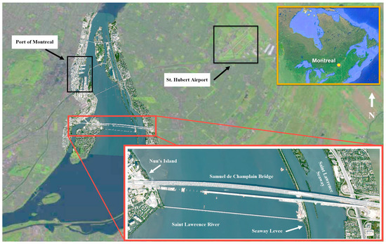
Figure 2.
Montreal metropolitan area in the Canadian province of Quebec. Airbus Pleiades 1-Amultispectral image from 21 September 2021 overlaid on ESRI image base map.
The Greater La Prairie Basin, which extends from the Lachine Rapids in the south to the Port of Montreal in the north, is a naturally occurring widening of the St. Lawrence River characterized by shallow, rocky subsurface ledges, strong currents, and variable ice cover in winter months. An artificial levee with locks separates the Greater La Prairie Basin from the St. Lawrence Seaway deep-draft vessel navigation channel and the depth-controlled, slow-flowing Lesser La Prairie Basin.
With a design life of 125 years, the Samuel de Champlain Bridge was slated for construction in June 2015 and opened to traffic in July 2019, replacing the old Champlain Bridge after 57 years in service. It carries eight lanes of road traffic on two separate decks—including one lane in each direction for buses and a dedicated lane for cyclists and pedestrians—and a third (central) deck for a light rail corridor.
With a total length of 3335 m, the SdC Bridge is made of three superstructures: the west approach (26 spans over 2044 m), the cable-stayed bridge (four spans over 529 m) with a 168 m high concrete tower, and the east approach (nine spans over 762 m) going over the seaway navigation channel (Figure 3). It is the world’s widest cable-stayed bridge with two planes of stay cables.
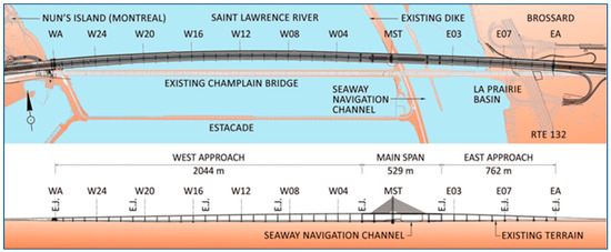
Figure 3.
Plan view (top) and elevation view (bottom) of the Samuel de Champlain Bridge [26] (Credit: Infrastructure Canada and TY Lin International).
The PS-InSAR deformation study, using high-resolution radar satellite imagery, focused on the entire length of the bridge from the west abutment (WA) to the east abutment (EA), thus including the whole 39 spans of the bridge. For the environmental study using multispectral and thermal infrared satellite imagery, it was decided to focus the analyses and observations on the 29 piers of the spans going over the Greater La Prairie Basin from the west abutment to the main span tower (MST), thus excluding the piers of the spans going over the St. Lawrence Seaway navigation channel where the water level is controlled independently.
3. Methodological and Theoretical Aspects
3.1. Acquisition of Radar Satellite Imagery and Related Ancillary Data
Radar imagery was obtained from the C-band RADARSAT-2 satellite operating in a sun-synchronous orbit at an altitude of 798 km with a repeat pass cycle of 24 days. The SLA12-D descending stack (acquired in SpotLight mode) was selected to perform the PS-InSAR analysis [27], since it reduced undesired radar effects and provided high sensitivity to deformations in the longitudinal direction of the bridge. The same stack was previously used to conduct PS-InSAR analyses over the nearby Jacques Cartier and Victoria Bridges [24], where the results were found to be satisfactory for this particular viewing geometry.
This stack of images consisted of 26 scenes acquired typically every 24 days from 21 June 2019 (10 days before the bridge’s official opening to traffic) to 4 July 2021 (approx. two years later). The typical image footprint measures 21.5 km in the range direction and 9.5 km in the azimuth direction. The SLA12-D stack characteristics include an incidence angle of 39°, a ground-range resolution of 2.5 m, and an azimuth resolution of 0.8 m (i.e., along the descending satellite track from north to south).
Ambient temperature measurements at times of satellite passes were obtained from Environment and Climate Change Canada, consisting of hourly temperature readings from the local Montreal/St. Hubert weather station, located at the Montreal/St. Hubert Airport, which is approximately 10 km NE of the Samuel de Champlain Bridge (Figure 2). Temperature measurements were extracted at 6:00 a.m. local time (or 11:00 UTC), which is the approximate time of the RADARSAT-2 descending satellite pass over Montreal. These ambient temperatures were used to estimate the thermal sensitivity coefficients for the InSAR targets measured over the bridge.
In a previous study [23], two different sets of temperature measurements were compared for bridge monitoring purposes: (i) ambient temperatures obtained from the nearest weather station, which was 23 km from the North Channel Bridge crossing the St. Lawrence River in Cornwall, Ontario, and (ii) surface temperatures measured with gauges placed on the bridge steel girders (not exposed to solar radiation). Over a wide range of temperatures (−20 °C to 25 °C), it was found that the two sets of temperature measurements (selected at times of ascending satellite image acquisitions at approximately 6 p.m. local time) correlated very well together (R2 = 97%), with the girder temperature being consistently higher by only 2 °C when compared with the ambient temperature obtained from the weather station. The effect of taking one set of measurements over the other on the determination of the InSAR thermal displacement results was found to be negligible.
3.2. PS-InSAR Analysis Method
This section briefly outlines the PS-InSAR analysis method that was used for the Samuel de Champlain Bridge case study in Montreal.
A backscatter analysis, combined with a review of the bridge construction drawings, is typically conducted to identify the bridge components from which the various radar signals originate before initiating the PS-InSAR analysis. The analysis of radar backscatters from some bridges can be complex due to the combination of effects such as layover (e.g., two or more spatially separated scatterers occurring in the same radar range), shadowing (e.g., incident radar signals blocked by other parts of the structure), multi-bounce (e.g., specular reflection) off the water surface and/or the bridge structure itself, as well as construction activity and seasonal effects (e.g., snow/ice accumulation in wintertime) that can reduce the number of valid measurement points on the bridge.
PS-InSAR (or PSI) is a remote sensing technique in which the amplitude and phase of complex radar images acquired at different times are combined into interferograms to measure deformations over large geographic areas at pixel resolutions down to the meter scale. Multiple processing techniques exist to exploit mature SAR image stacks to detect changes in the target deformation at accuracies down to the millimeter scale [28,29]. PSI can be used to analyze target phase quality using a spatially differential method, i.e., comparing the phase history of each target to that of its neighbours, to identify the subset of spatial targets with a high-quality phase. PSI is expected to produce its best results over highly coherent urban areas with a high density of manmade structures and little to no vegetation when C-band or X-band images are used. These areas must retain high coherence values throughout the entire observation period. With a sufficient number of persistent scatterers (PS), a dense geodetic network is formed, allowing deformation observations at small scales with fine accuracy. PSI has two main steps: (i) identification of coherent targets (i.e., those with sufficient phase quality); and (ii) estimation of the deformation time history for each coherent target. More details can be found elsewhere [4,5].
The InSAR study focused mainly on three different sets of displacement data:
- Average displacement linear rate (or velocity), expressed in mm/year and calculated over the 2-year acquisition period;
- Average displacement thermal sensitivity, expressed in mm/°C and calculated over the 2-year acquisition period;
- Displacement time series, expressed in mm and measured at times of image acquisition (every 24 days in this study).
3.3. PS Geolocation and Selection of PS Data Points for Analysis
Radar targets were geolocated using both global absolute coordinates (WGS84 horizontal and EGM96 vertical) and a local bridge-centric coordinate system for which the longitudinal direction goes from the west abutment to the east abutment of the bridge. After a series of target filtering, artifact removal, atmospheric error correction, and model optimization, refined sets of InSAR data were obtained over the bridge [27]. For verifying the correct positioning of radar targets, a single orthorectified Airbus Pleiades 1-A panchromatic satellite image of the bridge from 3 April 2021 was used. Several control points along the bridge deck were identified to make corrections to the WGS84 coordinates of the persistent scatterers to ensure adequate alignment with key bridge features on the orthorectified image.
Figure 4 illustrates a selection of PS measurement points over the bridge deck from piers W20 to W17, for which the nearby areas are identified with transparent blue rectangular shapes. It is interesting to see that the barriers and railings on each edge of the exterior decks are the bridge elements that generated the most persistent scatterers. In addition, PSs that are known to be coming from piers are found to be located precisely on the orthorectified image. The adequate transverse positioning of PSs can also be appreciated at the enlarged scenic overlook area of the bike path located on the north side of the bridge between piers W18 and W17. As expected, the middle of the roadways, being a smooth surface, typically returned very few PSs due to specular reflection away from the satellite sensor. Thus, Figure 4 confirms the adequate positioning of the PS data points. Similar observations were made on the remaining portion of the bridge.
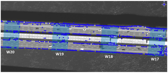
Figure 4.
InSAR targets (blue dots) over the bridge deck between piers W20 and W17 (with their nearby areas delimited by the transparent blue rectangular shapes).
3.4. Estimation of InSAR Displacement
Radar satellites take readings along the sensor’s line of sight (LOS), which is perpendicular to the satellite flight path (Figure 5, right). By convention, positive values indicate movement toward the satellite sensor, while negative values indicate movement away from the satellite sensor (Figure 5, left).
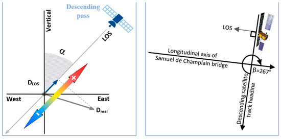
Figure 5.
(Left): Elevation view of real movement projected onto the line of sight for a descending pass (credit: TRE Altamira); (Right): Plan view of satellite trajectory relative to bridge orientation.
For comparison and validation purposes, converting vertical and horizontal components of displacement into the satellite line of sight is straightforward, as shown below in Equation (1), which is adapted from [30] for a bridge-centric coordinate system. If the transverse displacement across the deck can be neglected, then Equation (1) reduces to Equation (2) where the vertical and longitudinal displacement components are non-negligible [24]. In addition, Equations (3) and (4) can be derived from Equation (2) only if DV or DL, respectively, can also be assumed to be small or negligible compared with the overall movement being monitored. Consequently, Equations (1)–(4) provide a convenient means for comparing satellite displacement measurements with data from in situ sensors or prediction models.
where DLOS is the line-of-sight displacement toward the satellite sensor, DV is the vertical component in the upward direction, DL is the horizontal component in the longitudinal direction of the bridge (in our case from west to east), DT is the horizontal component in the transverse direction of the bridge, α is the incidence angle of the satellite line of sight (e.g., 39° for the SLA12-D stack), and β is the angle measured clockwise from the satellite track heading to the bridge longitudinal axis (e.g., 267° for SdC Bridge and SLA12-D stack), as illustrated in Figure 5 (right).
DLOS = DV cos α − DL sin α sin β + DT sin α cos β
DLOS = DV cos α − DL sin α sin β if DT ~ 0
DL = −DLOS/(sin α sin β) if DV & DT ~ 0
DV = DLOS/cos α if DL & DT ~ 0
The displacement thermal sensitivity is a type of measurement from the PS-InSAR analysis that is of interest for monitoring bridges, since they respond well to changes in ambient temperature. The thermal behaviour of the bridge can easily be calculated from the known geometric bridge configuration (e.g., span lengths, expansion joint locations, connection details allowing or restricting thermal movement between spans) and the ambient temperature data that can be acquired from in situ sensors, local weather stations, or thermal infrared satellite imagery. By comparing satellite measurements of thermal movement with actual theoretical estimates, one can confirm whether the bridge is moving according to design, while observed deviations from the expected thermal behaviour could flag a problem (e.g., restrained thermal expansion due to a damaged expansion joint or the resulting effect of an unexpected non-thermal movement). The axial thermal movement of a 1D element in the longitudinal direction is simply taken as:
where L is the length of the bridge element under thermal movement, CTE is the coefficient of thermal expansion of the given bridge element, and ΔT is the change in ambient temperature from the first image acquisition. Detailed calculation procedures for complex bridges are given elsewhere [24]. Equations (3) and (5) were used to validate the satellite-measured displacement thermal sensitivity data presented later. When two image stacks from two opposite viewing geometries are available (i.e., one ascending and one descending), 2D decomposition can be carried out on the two stacks to obtain directly the vertical and the east–west components of displacement. However, with only one stack of SAR images being available (SLA12-D), we had to assume that the most significant component of movement on the bridge is in the longitudinal direction for this relatively long-span, east–west-oriented bridge, and thus we considered the vertical movement of the deck to be small in comparison (this assumption will be verified in Section 4.2).
DL = L × CTE × ΔT
Since the radar signals were mostly reflecting from the barriers and steel railings on each side of the two exterior roadway decks, one additional assumption needed to be made: the movement of the barriers and railings is similar to that of the concrete bridge deck, given their strong connection and similar coefficient of thermal expansion. A coefficient of thermal expansion of 0.000012 was selected to match that of the steel railings. In Equation (2), DV was assumed to be small compared with DL, and the latter was calculated with Equation (3), considering (i) continuous sections of bridge spans between the expansion joints (“E.J.” symbols in Figure 3) and (ii) thermal expansion being positive in the eastward direction.
3.5. Acquisition of Multispectral Satellite Imagery
A mono ortho image stack comprising six panchromatic-only (PAN) Maxar Worldview-2/Worldview-3 [31] and ten panchromatic + four-band multispectral (MS) Airbus Pleiades 1A/1B images [32] was acquired as part of a companion observational study to the PS-InSAR study. Images were corrected for top-of-atmosphere reflectance, georeferenced and co-registered using existing photogrammetric ground control monuments in the City of Montreal, and orthorectified using the high-resolution Canadian digital elevation model (HR-CDEM). Horizontal coordinates for the final image stack are in the Canadian spatial reference system realization of the North American Datum of 1983 (NAD83 CSRS), projected into planar coordinates using Canadian Modified Transverse Mercator (MTM) zone 8 projection. Orthometric heights are given relative to the Canadian Geodetic Vertical Datum of 2013. For comparison with the InSAR dataset, measurement point coordinates were transformed into WGS84 and projected into UTM zone 18 coordinates in ArcGIS Pro V2.7 [33].
MS images were selected to overlap the InSAR observation period from March 2019 to September 2021. Selection criteria included <20% cloud cover, lack of aerosols (e.g., fog, smoke) near the ground level, minimal sun glint, and a clear view of the St. Lawrence River surface near the Samuel de Champlain and Nun’s Island Bridges. Images were then inspected to detect changes over the study period that could be relevant to InSAR observations or that could provide context to the interpretation of InSAR deformation data.
3.6. Acquisition of Thermal Infrared Imagery
Surface temperatures from satellite imagery were obtained using the thermal infrared sensor (TIRS) on the Landsat-8 (2019–2022) and Landsat-9 (2022 only) satellites operated by the U.S. Geological Survey [34]. These satellites operate in a sun-synchronous orbit with a repeat pass cycle of 16 days. The TIRS instrument band 10 observes skin-of-the-earth and skin-of-the-water temperatures in the wavelength of 10.30–11.30 μm (long-wave infrared, or LWIR) at a native spatial resolution of 100 m (later subsampled to 30 m resolution [35]). Landsat satellite overflights of the Montreal metropolitan area occur at approximately 15 h 30 Greenwich time (10 h 30 local standard time).
A set of 30 Landsat TIRS images of skin-of-the-water temperatures acquired for the years 2019–2021 (corresponding to the InSAR dataset acquisition period) was selected for comparison with air temperatures measured from the Montreal/St. Hubert weather station. Image selection criteria were based on cloud-free skies and lack of other masking features (such as fog or smoke), while satellite path and frame number were not considered. Images were downloaded from the USGS Earth Explorer website and projected into WGS84 UTM zone 18 planar coordinates in Global Mapper V21 software [36].
Projected images were imported into ESRI ArcGIS Pro 2.7, clipped to the AOI, and finally scaled and converted from the native digital number to °C using the following formula published by the USGS [34]:
where T is temperature (°C) and D is the pixel value of the raster at point coordinates (x,y).
Tx,y = (Dx,y × 0.00341802 + 149) − 273.15
The width of the SdC Bridge deck (60 m) in the sampling area is less than the 100 m native pixel resolution of the Landsat 8/9 TIRS images. In order to exclude pixels where the subsampled pixel temperature value may comprise a blend of both water and bridge deck measurements, a sampling line was drawn approximately 200 m downstream of the bridge. Sampling points were drawn along the line, with point locations aligned with the bridge piers. Water surface temperatures were extracted at the sampling points and interpolated in time to match the acquisition dates of the radar satellite imagery.
3.7. Measurement of Water Depths
Water depths at the bridge piers were measured relative to the low water datum (LWD) located at the Port of Montreal (Figure 2) and were acquired by echosounder as part of the bridge pre-construction environmental baseline survey [37] and with historical single-beam echosounder surveys conducted by the Canadian Hydrographic Service (CHS). Soundings were used to build a triangular irregular network (TIN) at 3 m resolution and minimally smoothed to create a bathymetric digital terrain model (DTM) of the Greater La Prairie Basin. Total estimated water depths (measured from the natural river bottom to the top of the water surface) were computed by adding the water level above the low water datum recorded at the Montreal Jetée no. 1 gauge (operated by Port of Montreal Authority) to water depths at LWD from the pre-construction bathymetric survey.
4. Results and Analyses
4.1. Selected InSAR Displacement Results
Estimated LOS displacement velocity data (expressed in mm/year in Figure 6), which can be used to detect early signs of settlement, for example, did not reveal any significant deformation of concern over the bridge in general, as it would normally be expected for a new bridge with pier foundations built on bedrock.

Figure 6.
Point cloud of LOS displacement velocity data (mm/year) superposed over an orthorectified image of the bridge—from west to east abutments of SdC Bridge.
Estimated LOS displacement thermal sensitivity data (expressed in mm/°C in Figure 7) reveal some interesting trends. For instance, the measurements display a repetitive pattern along the bridge, with the most negative values (approx. −2 mm/°C LOS) near the western ends of the continuous sections of spans between expansion joints, and the most positive values (approx. +2 mm/°C LOS) near their eastern ends. This confirms the adequate thermal behaviour of the bridge given the known distances and connection details of the different bridge spans and their expected thermal expansion away from the pinned location of each independent section of the continuous spans.

Figure 7.
Point cloud of LOS displacement thermal sensitivity data (mm/°C) superposed over an orthorectified image of the bridge—from west and east abutments of SdC Bridge.
Figure 8 presents a close-up view of the data from Figure 7 for the section of continuous spans between the west abutment and pier W21. In addition to confirming the thermal deformation pattern observed in Figure 7, two interesting PS features can be observed. The first one relates to groups of returns over the piers (showing through the gaps between the central deck and external decks) displaying moderate LOS values up to approx. ±0.5 mm/°C. The second observation appears to be reflections from the overhead sign gantry located at W22; however, this subset of data is not of interest to this study. More analysis of InSAR thermal displacement data is presented in Section 4.2.
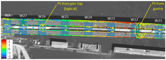
Figure 8.
Point cloud of LOS displacement thermal sensitivity data (mm/°C) superposed over an orthorectified image of bridge from first expansion joint (WA) to second expansion joint (W21).
4.2. Validation of InSAR Displacement Thermal Sensitivity Measurements
Figure 9 illustrates the LOS displacement thermal sensitivity data of Figure 7 displayed along the distance from the west abutment to the east abutment, with LOS values ranging from approximately −2 to +2 mm/°C according to the repetitive thermal pattern observed earlier in Figure 7. It is noted that only the best quality measurement points are presented in Figure 9, based on a 0.9 minimum temporal coherence threshold. The interpretation of the data is presented in the next paragraph.
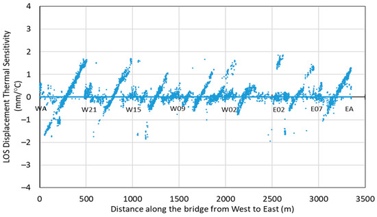
Figure 9.
LOS displacement thermal sensitivity data measured along the bridge.
Figure 10 presents the comparison of the satellite-measured displacement thermal sensitivity data with theoretical estimates calculated in the west–east longitudinal direction of the bridge using Equations (3) and (5). It is noted that only the best quality measurement points are presented in Figure 10, based on a minimum temporal coherence threshold of 0.9.
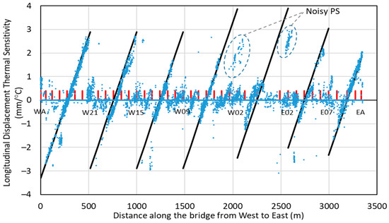
Figure 10.
Comparison between InSAR measurements (blue dots) and theoretical estimates (black lines) of the horizontal component of thermal displacement along the bridge. The red tick marks indicate the positions of the piers and abutments.
Four key observations can be made from the InSAR data presented above in Figure 10, as follows.
The first observation relates to the main repetitive thermal displacement pattern observed along the bridge length, which was found to be well captured by the satellite data when compared with the theoretical estimates calculated with Equations (3) and (5) from the known bridge geometry, connection details, and ambient temperature data. The excellent alignment of the InSAR data (blue dots) with the theoretical calculations (black lines) clearly confirms the assumption of negligible vertical thermal displacements compared with the much larger longitudinal thermal displacements used in Equation (3) when calculating the longitudinal displacements from the LOS InSAR displacement data.
The second observation is a small exception to the first observation. At the fifth section of continuous spans from the west, the InSAR data points do not align perfectly as a straight line but instead display a very small curvature. This suggests that a non-negligible component of vertical displacement may be affecting the calculated results over the main section of the cable-stayed bridge, which is where the two longest spans of the entire bridge are located (W1-MST = 124 m; MST-E1 = 240 m). In light of the above, it may be suggested that in most sections of the SdC Bridge where the supported span length is typically 80 m or less, it is safe to assume negligible vertical movement at each single span relative to the larger movement of the continuous section of connected spans. However, with single span lengths up to 124 m and 240 m on the cable-stayed bridge superstructure, vertical movement (e.g., deflections, especially at mid-span) may start to become non-negligible, resulting in small deviations from the required assumption used in Equation (3).
The third observation, as earlier noted and described in Figure 8 and Figure 9, is about the groups of points with moderate values lower than ±1 mm/°C along the bridge, which appear to be returns from the piers.
The fourth observation is on some noisy measurements from persistent scatterers identified in Figure 10. To help with the discussion, Figure 11 illustrates a 3D rendering of the cable-stayed superstructure of the SdC Bridge from Google Earth Pro (top) and the corresponding color-coded map of LOS displacement thermal sensitivity data over an orthorectified image of the bridge. The noisy measurements are mainly represented by the red PSs observed over the deck areas near W02 and E02. The study of the bridge geometry and materials at these two locations suggests that these permanent scatterers are just noisy measurements and cannot be identified as either layover or multibounce effects, since they do not seem to be displaced in the correct direction relative to the objects they could be originating from, knowing that the satellite look direction is toward the west.

Figure 11.
(Top): Google Earth image of SdC’s main span (dated 2 July 2019); (bottom): color-coded map of LOS displacement thermal sensitivity data over orthorectified image (dated 3 April 2021).
4.3. Analysis of Multispectral (MS) and Infrared Imagery and Environmental Data
This section seeks to find out whether different types of environmental data obtained from remotely sensed multispectral and infrared imagery and/or in situ water level data could have an effect on some structural deformations of the bridge observed from the PS-InSAR analysis, and whether they could provide additional context to inform the bridge stability assessment. In other words, we wish to find out whether additional info obtained from these sets of imagery and in situ water level gauges could either confirm some observations from the PS-InSAR analysis or at least complement them.
As previously stated, we focused our analyses and observations on the bridge deck, piers, and their surroundings going from the west abutment to the main span tower. A historical bathymetry study is illustrated in Figure 12. The south-to-north-oriented main river thalweg, rocky ridges running parallel to the thalweg, and a shallow shelf north of Nun’s Island are visible in the image. Currents are strongest in the main river thalweg and decrease proportionally with decreasing river depth [37].
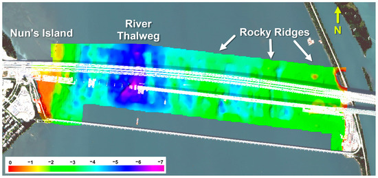
Figure 12.
Historical bathymetry at low water datum from pre-construction and navigation surveys over the west approach up to the main span tower of the Samuel de Champlain Bridge, overlaid on a Pleiades 1A pan-sharpened multispectral image from 20 September 2021. (Depths are in meters).
4.3.1. Multispectral Satellite Imagery Analysis
The two most prominent observations of the river surface and riverbed during the study period were ice accumulation and the intentional deconstruction of gravel pads for construction work located near the shores of Nun’s Island to the west and the St. Lawrence Seaway levee to the east.
River ice in the La Prairie Basin between the months of November 2019–March 2020 and November 2020–March 2021 was observed in the image stack. In the surroundings of the SdC Bridge, the ice cover varied in spatial extent and concentration. The most common forms of river ice observed during the study were landfast ice, which is fixed to the shore, very close ice or consolidated ice, where 90% or more of the water surface is covered by ice, and open or free-floating ice, where 20–50% of the water surface is covered by drifting pieces of ice [35]. On the western side of the study area, landfast ice was observed in winter months to surround the gravel pad between the shore of Nun’s Island and pier W23 of the SdC Bridge. On the eastern side of the study area, very close ice and consolidated ice were observed upstream of the gravel pad near pier W01, landfast ice was observed downstream before April 2020, while open water was observed in the winter months of 2020–2021. This variation in ice coverage on the east side of the La Prairie Basin is mainly attributed to the Montreal Estacade, which is an ice-control structure approximately 400 m upstream of the SdC bridge. Examples of different types of ice cover around the SdC Bridge are shown in Figure 13.
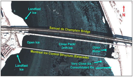
Figure 13.
Airbus Pleiades 1A multispectral image from 8 March 2021 showing ice cover and ice type in the vicinity of the Samuel de Champlain Bridge. Landfast ice and consolidated river ice appear bright white due to snow cover on top of the ice surface.
Gravel pads used by construction barges and associated equipment such as temporary wharves were observed in the MS imagery from March 2019 to July 2020. The gravel pad on the east side of the St. Lawrence River extended approximately 190 m west of the bank of the St. Lawrence Seaway levee. At its maximum extent, it encased piers W01 and W02. On the west side of the river, a larger and wider gravel pad extended approximately 460 m east of the shoreline on Nun’s Island. At its maximum extent, piers W22 through to W27 were completely encased by the pad. Construction barges and temporary vessel mooring facilities were positioned on the north side of the west gravel pad.
The pad on the west side of the river was dismantled in stages, with the fill material on the west side of the river removed between July 2019 and March 2020, which was confirmed by the bridge authority. Dredging equipment for final removal was observed in an image from July 2020, and the above-surface portion of the pads was removed completely by September 2020. The gravel pad around piers W01 and W02 was also removed between July and September 2020. We infer from the flow direction of turbulent vortices and sediment boils on the river surface and from chunks of open ice in winter months that some of the fill for the gravel pad originating on Nun’s Island remained present below the waterline, even though the above-waterline portion of the pads had been removed. In other words, the river current is deviating around a subsurface obstruction. The change in the current direction around the remaining fill material was observed to occur from September 2020 until July 2021.
Figure 14 shows a time series of the change in river current direction around the submerged remnant fill adjacent to Pier W23. Dredging equipment and part of the gravel pad are visible in (A). Landfast ice and floating open ice are present in (C). We do not observe a similar deviation in current direction around piers to the east of the La Prairie Basin.
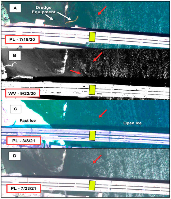
Figure 14.
Time series of Airbus Pleiades (PL) multispectral and Maxar Worldview (WV) panchromatic images of the St. Lawrence River downstream of pier W23 (yellow box). Red arrows indicate turbulent structures that show the change in river current direction around the remnants of the gravel pad. (A) Pleiades image from 18 July 2020, with dredging equipment indicated by white arrows. Note that the riverward extent of the gravel pad is immediately to the left of Pier W23. (B) Worldview image from 22 September 2020. (C) Pleiades image from 8 March 2021, where the change in current direction is visible alongside open and landfast ice. (D) Pleiades image from 23 July 2021.
4.3.2. Thermal Infrared Satellite Imagery Analysis
In this section, we assess the accuracy of temperature measurements obtained from longwave thermal infrared satellite imagery compared with ambient temperature obtained from the nearby weather station (which was located 10 km away from the monitored area of interest, Figure 2). A second goal is to assess whether temperature measurements from satellite imagery could be a suitable alternative to ambient air temperature measurements in cases where data from in situ temperature sensors or nearby weather stations are either not available or where such data are incomplete or unreliable. Figure 15 shows an example of TIRS imagery in the vicinity of the SdC bridge, with a Maxar Worldview panchromatic band image acquired eight days later showing how different features of interest on the river’s surface appear in the very-high-resolution (50 cm) Maxar image and the coarser (30 m)-resolution TIRS image. Note that these images are taken in winter months, and thus the temperature of the skin-of-the-water on the free-flowing St. Lawrence River is warmer than the temperature of the bridge deck, snow-covered landfast ice, or upland surfaces such as on Nun’s Island.
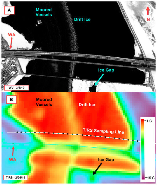
Figure 15.
(A) Worldview-2 panchromatic-band satellite image acquired 6 March 2019, 50 cm resolution, compared with (B) Landsat TIRS thermal image acquired 26 February 2019, 30 m resolution.
Figure 16 compares time-series temperature data for the piers over water and the top surface of the west abutment (fully located onshore) from TIRS imagery, and the ambient air temperature measured at the Montreal/St. Hubert weather station (WS).
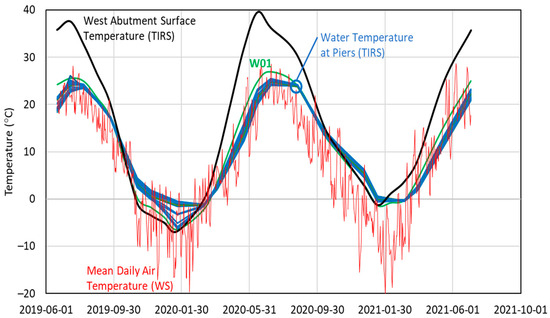
Figure 16.
Temperature measured by satellites at each selected pier and WA over time, except for the ambient air temperature, which was obtained from the Montreal/St. Hubert weather station.
Temperature variability across the La Prairie Basin is lowest during summer and autumn months when river water is generally well mixed and ice is not present. It can be observed that the water surface temperature at any given time can vary within 5 °C for the different piers depending on time of year and river characteristics, with variability lowest for piers W16 to W21 which are near the river thalweg and highest for piers near Nun’s Island and the St. Lawrence Seaway levee, which are in very shallow water and may be surrounded by landfast or very close ice in winter months. Temperature observations at the piers that are very close to land (W01 & W27) may also have some pixel blending during ice-free months, at which time the temperature at a sample point may include measurements from both the water and the nearby shoreline. In winter months, sub-freezing temperatures from extracted TIRS sample data points correspond to the presence of ice around those piers, which was confirmed by the multispectral image stack. Skin-of-the-earth temperatures observed at the west abutment may exceed the mean daily ambient air temperature by more than 10 °C in summer months, which is attributed to increased thermal retention of the paved surface of the roadway.
4.3.3. Assessment of River Depth
Water depth could give an appreciation of the lateral pressure applied on the bridge piers by the river current mainly in the transverse direction of the bridge. Higher water levels also correspond to increased flow volume, which in turn leads to higher current speeds and thus a greater likelihood of scouring potential during high-flow periods. Understanding the bridge behaviour and related PS-InSAR returns during normal seasonal flow conditions can provide context for deviation from the baseline during atypical conditions (such as significant flooding).
Water depths relative to the low water datum at the Montreal Jetée no. 1 gauge follow expected seasonal trends and are within expected historical limits. We assume that meteorological components of water levels (wind pushing water away from a lee shore and vice versa) are insignificant. Figure 17 shows the results at selected piers calculated from the water level gauge located at the Port of Montreal. Note that depths are represented with the sign convention of negative down.
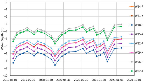
Figure 17.
Total water depth (LWD datum depth + water level) at each selected pier over time. The symbol X indicates a pier at an expansion joint and the symbol P indicates a pier at a pinned location. (Note that curves W24 and W02 overlap).
5. Adding Environmental Context to Enhance or Complement Bridge Stability Assessment
To explore how environmental data from multispectral and infrared imagery may be used to provide context to bridge structural deformations, processed InSAR LOS displacement data points were imported into QGIS V3.34 [38], clipped to the bridge deck areas over the piers, averaged for each pier location, and compared with the water depth and water temperature data collected at each pier and at each time of image acquisition.
When using the MS image stack to identify correlations with the InSAR structural deformation data, it is essential to comprehend the types of features observed in the imagery that are likely to contribute to structural health risks and what those risks entail. For example, observing vessels in the St. Lawrence Seaway downstream of the bridge is not likely to be relevant to structural health monitoring, but the presence of landfast or consolidated ice surrounding a bridge pier or deviations in the appearance or direction of the turbulent wake downstream of a bridge pier (such as described in Figure 14) may be.
5.1. Dredging Activity
The most significant event posing risks to the bridge observed in the MS image stack was the removal by dredging of the gravel pads built during bridge construction. Dredging activity around bridge piers can pose risks of settlement due to excess sediment removal [39,40] or damage from dredging vessels or dredging equipment striking the bridge. We did not observe any evidence of unexpected bridge deformations in the InSAR data throughout the period of dredging operations and gravel pad removal, nor did we observe any evidence of unexpected bridge deformations in the year following pad removal, where the remaining fill material below the waterline was left to be eroded by normal river processes.
5.2. Ice Accumulation
River ice is a potential cause of damage to bridge piers and abutments, such as impact damage from ice striking piers or localized scouring from water flow diverting around ice [41]. The Samuel de Champlain Bridge is located downstream of both the Lachine Rapids and the Montreal Estacade ice-control structure, which work together to minimize the likelihood of large pieces of drifting ice impacting or becoming consolidated against bridge piers. Landfast ice accumulations were observed in the vicinity of the gravel pads on both sides of the river before the dredging operations started. With the gravel pads in place, ice accumulation would put pressure on the gravel pads, but not directly on the bridge piers. While no unexpected bridge deformation was observed during the study period, the question of whether the effects of pressure from landfast, very close, or consolidated ice on the bridge piers are observable using PS-InSAR remote sensing remains inconclusive. This serves as a reminder that the SAR satellite sensor is not very sensitive to north–south deformations (i.e., transverse deformations from ice loads). More details are provided in the discussion section.
5.3. Effect of Ambient Temperature
The relations between the LOS displacement and time are illustrated in Figure 18, indirectly showing the effect of seasonal variations of temperature. Note that the curves for piers W02, W09, W15, and W21 are not shown, since these four locations coincide with expansion joints where the thermal displacements would have opposite values depending on the side of the expansion joint at which the measurement points fall, thus affecting the calculation of the averaged values at those four pier locations.
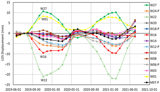
Figure 18.
InSAR LOS displacements of deck at selected piers as a function of time. The symbol P indicates a pier at a pinned location.
Two interesting observations can be made from Figure 18. One is the strong dependency of the LOS displacement with the seasonal change in ambient temperature (as normally expected), which is consistent with the data presented in Figure 10.
The other observation is about the deck areas over piers W16 and W22 displaying strong negative LOS displacements (down–west) with decreasing temperature (going into the winter months), while the deck areas over piers W01 and W27 experienced strong positive LOS displacement (up–east) with decreasing temperature. This is explained by the different connection details between the supported spans at the piers and the direction of thermal expansion that is allowed to occur by design. For example, the returns at W16 and W22 are on spans expanding toward the east (and toward the satellite sensor), while the returns at W01 and W27 are on spans expanding toward the west (and away from the satellite sensor) (Figure 10).
6. Discussion
In InSAR analyses, the geographic orientation of the bridge plays a key role in the satellite sensor sensitivity to the different components of displacement, since the SAR satellite sensor is mainly sensitive to the east–west and up–down directions. In the case of the Samuel de Champlain Bridge, the angle measured clockwise from the satellite track heading to the bridge longitudinal axis is 267° (i.e., β in Equations (1)–(3) and Figure 5). This results in a relative sensitivity of approximately 5% for any movement occurring in the transverse direction. In the case of a non-turbulent laminar river flow, the ice load and water pressure applied on the SdC Bridge piers could be said to be primarily perpendicular to the bridge. Given this observation, it is fair to expect that ice load and water pressure effects could not be observed in the InSAR results as mentioned earlier. However, this does not diminish the value of such data in providing additional context for the bridge stability assessment, as demonstrated above. For instance, Figure 14 gives a good example of where a subsurface obstruction (the remnants of a gravel pad) can cause the angle of attack of the river current on pier W23 to deviate from the expected transverse direction. This warrants further investigation on bridges that are not primarily aligned with the east–west direction to find out whether the effects of river depth, river current direction deviation, and ice loading can be observed in InSAR deformation data.
7. Conclusions
An overarching goal of the partnership led by the National Research Council of Canada is to identify and validate cost-effective, scalable methods to determine threats to bridge structural stability in the uncertain context of climate change. Space-borne remote sensing was applied, validated, and demonstrated in a case study on the new Samuel de Champlain Bridge in Montreal, Canada, in which high-resolution C-band radar satellite imagery was acquired and analyzed using the PS-InSAR technique to derive bridge displacements and compare them against theoretical estimates.
PS-InSAR thermal deformation measurements (projected in the bridge longitudinal direction) compared well with their theoretical estimates based on the known bridge geometry (e.g., span lengths and connection details) and ambient temperature data. Displacement velocity measurements gave no evidence of settlement or other non-thermal movement during the 2-year monitoring period, which is expected for a new bridge with pier foundations built on bedrock. Taking these measurements as a baseline, future updates of these measurements will enable the bridge authority to identify early signs of unexpected bridge movement and take corrective action in due time.
To give additional context for the analysis and interpretation of the InSAR deformation results, environmental data obtained from multispectral and thermal infrared satellite imagery and in situ instruments were also investigated for potential effects on structural deformations. The main features of interest observed in the multispectral imagery were gravel pads for construction purposes and seasonal ice formation. A strong dependency of InSAR LOS displacement measurements on ambient temperature was observed. No evidence of unexpected bridge movement during or after dredging work associated with the removal of the gravel pads was observed.
The availability of environmental data obtained remotely from multispectral and infrared satellite imagery was found to be very informative and useful in providing context for the bridge stability assessment. Ambient temperature measurements from thermal infrared satellite imagery were found to be a suitable alternative to those measured at the nearby weather station, which can be useful in cases where data from in situ temperature sensors or nearby weather stations are not available or not fit for purpose.
Concerning river depth and ice loading with resulting lateral pressure on piers, no significant correlation was found with the structural deformation results from the InSAR analysis; however, this is partly because these particular effects act primarily along the river flow in the north–south direction, to which the radar satellite sensor is not very sensitive. This warrants further investigation on bridges that are not primarily aligned with the east–west direction.
Author Contributions
Conceptualization, D.C. and H.S.; methodology, D.C. and H.S.; validation, D.C. and H.S.; formal analysis, D.C. and H.S.; investigation, D.C. and H.S.; resources, D.C.; data curation, D.C. and H.S.; original draft preparation, D.C. and H.S.; manuscript review and editing, D.C. and H.S.; visualization, D.C. and H.S.; supervision, D.C.; project administration, D.C.; funding acquisition, D.C. All authors have read and agreed to the published version of the manuscript.
Funding
This research was jointly funded by Transport Canada, Infrastructure Canada, and the National Research Council Canada through its initiative on Climate Resilient Built Environment.
Data Availability Statement
The SAR images were obtained from the Canadian Space Agency and the multispectral and infrared images were obtained from the European Space Agency under restricted licence agreements, which do not support public distribution.
Conflicts of Interest
The authors declare no conflicts of interest. The funders had no role in the design of the study; in the collection, analyses, or interpretation of the data; in the writing of the manuscript; or in the decision to publish the results.
References
- U.S. Department of Transportation, Federal Highway Administration, and Federal Transit Administration. Status of the Nation’s Highways, Bridges, and Transit: Conditions & Performance Report to Congress, 24th ed.; U.S. Department of Trasnsportation: Washington, DC, USA, 2021; 596p. [CrossRef]
- FCM. Canadian Infrastructure Report Card 2019—Monitoring the State of Canada’s Core Public Infrastructure; The Canadian Federation of Municipalities: Ottawa, ON, Canada, 2019; 56p. Available online: http://canadianinfrastructure.ca/downloads/canadian-infrastructure-report-card-2019.pdf (accessed on 5 February 2024).
- PIEVC. Adapting to Climate Change—Canada’s First National Engineering Vulnerability Assessment of Public Infrastructure, Public Infrastructure Engineering Vulnerability Committee, Engineers Canada, April 2008. 76p. Available online: https://pievc.ca/wp-content/uploads/2020/12/adapting_to_climate_change_report_final.pdf (accessed on 5 February 2024).
- Crosetto, M.; Monserrat, O.; Cuevas-González, M.; Devanthéry, N.; Crippa, B. Persistent Scatterer Interferometry: A review. SPRS J. Photogramm. Remote Sens. 2016, 115, 78–89. [Google Scholar] [CrossRef]
- Ferretti, A.; Monti-Guarnieri, A.; Prati, C.; Rocca, F.; Massonnet, D. InSAR Principles: Guidelines for SAR Interferometry Processing and Interpretation; European Space Agency Publication TM-19, European Space Agency: Noordwijk, The Netherlands, 2007; 48p, Available online: https://www.esa.int/About_Us/ESA_Publications/InSAR_Principles_Guidelines_for_SAR_Interferometry_Processing_and_Interpretation_br_ESA_TM-19 (accessed on 5 February 2024).
- Pieraccini, M. Monitoring of Civil Infrastructures by Interferometric Radar: A Review. Sci. World J. 2013, 2013, 786961. [Google Scholar] [CrossRef] [PubMed]
- Camassa, D.; Vaiana, N.; Castellano, A. Modal Testing of Masonry Constructions by Ground-based Radar Interferometry for Structural Health Monitoring: A Mini Review. J. Front. Built Environ. 2023, 8, 1065912. [Google Scholar] [CrossRef]
- De Pasquale, G.; Bernardini, G.; Ricci, P.P.; Gentile, C. Ambient Vibration Testing of Bridges by Non-contact Microwave Interferometer. IEEE Aerosp. Electron. Syst. Mag. 2010, 25, 19–26. [Google Scholar] [CrossRef]
- Cigna, F.; Lasaponara, R.; Masini, N.; Milillo, P.; Tapete, D.; Gloaguen, R.; Thenkabail, P. Persistent Scatterer Interferometry Processing of COSMO-SkyMed StripMap HIMAGE Time Series to Depict Deformation of the Historic Centre of Rome, Italy. J. Remote Sens. 2014, 6, 12593–12618. Available online: https://www.semanticscholar.org/paper/Remote-Sensing-Persistent-Scatterer-Interferometry-Cigna-Lasaponara/299acd1e090d514b9c883ea174ffd943ecbf0d31 (accessed on 5 February 2024). [CrossRef]
- Roccheggiani, M.; Piacentini, D.; Tirincanti, E.; Perissin, D.; Menichetti, M. Detection and Monitoring of Tunneling Induced Ground Movements Using Sentinel-1 SAR Interferometry. J. Remote Sens. 2019, 11, 639. [Google Scholar] [CrossRef]
- Cusson, D.; Ghuman, P.; McCardle, A. Satellite Sensing Technology to Monitor Bridges and Other Civil Infrastructures. In Proceedings of the 5th International Conference on Structural Health Monitoring of Intelligent and Other Civil Infrastructure (SHMII-5), Cancun, Mexico, 11–15 December 2011; 9p. Available online: https://nrc-publications.canada.ca/eng/view/object/?id=368bf6b7-2364-42c1-a75f-c772312f13c5 (accessed on 5 February 2024).
- Sousa, J.J.; Hlaváčová, I.; Bakoň, M.; Lazecký, M.; Patrício, G.; Guimarães, P.; Ruiz, A.M.; Bastos, L.; Sousa, A.; Bento, R. Potential of Multi-temporal InSAR Techniques for Bridges and Dams Monitoring. Procedia Technol. 2014, 16, 834–841. [Google Scholar] [CrossRef]
- Selvakumaran, S.; Plank, S.; Geiß, C.; Rossi, C.; Middleton, C. Remote Monitoring to Predict Bridge Scour Failure Using Interferometric Synthetic Aperture Radar (InSAR) Stacking Techniques. Int. J. Appl. Earth Obs. Geoinf. 2018, 73, 463–470. [Google Scholar] [CrossRef]
- Milillo, P.; Giardina, G.; Perissin, D.; Milillo, G.; Coletta, A.; Terranova, C. Pre-Collapse Space Geodetic Observations of Critical Infrastructure: The Morandi Bridge, Genoa, Italy. J. Remote Sens. 2019, 11, 1403. [Google Scholar] [CrossRef]
- Lazecky, M.; Hlavacova, I.; Bakon, M.; Sousa, J.J.; Perissin, D.; Patricio, G. Bridge Displacements Monitoring Using Space-Borne X-Band SAR Interferometry. IEEE J. Sel. Top. Appl. Earth Obs. Remote Sens. 2016, 10, 205–210. [Google Scholar] [CrossRef]
- Zhao, J.; Wu, J.; Ding, X.; Wang, M. Elevation Extraction and Deformation Monitoring by Multitemporal InSAR of Lupu Bridge in Shanghai. J. Remote Sens. 2017, 9, 897. [Google Scholar] [CrossRef]
- Hoppe, E.J.; Novali, F.; Rucci, A.; Fumagalli, A.; Del Conte, S.; Falorni, G.; Toro, N. Deformation Monitoring of Posttensioned Bridges Using High-Resolution Satellite Remote Sensing. J. Bridge Eng. 2019, 24, 04019115. [Google Scholar] [CrossRef]
- Jung, J.; Kim, D.J.; Vadivel, S.K.P.; Yun, S.H. Long-term Deflection Monitoring for Bridges Using X and C-band Time-Series SAR Interferometry. J. Remote Sens. 2019, 11, 1258. [Google Scholar] [CrossRef]
- Selvakumaran, S.; Webb, G.; Bennetts, J.; Rossi, C.; Barton, E.; Middleton, C. Understanding Insar Measurement Through Comparison with Traditional Structural Monitoring—Waterloo Bridge, London, IGARSS. In Proceedings of the 2019 IEEE International Geoscience and Remote Sensing Symposium, Yokohama, Japan, 28 July–2 August 2019; pp. 6368–6371. [Google Scholar] [CrossRef]
- Acton, S. Sinkhole Detection, Landslide and Bridge Monitoring for Transportation Infrastructure by Automated Analysis of Interferometric Synthetic Aperture Radar Imagery; Final Report No. RITARS11-H-UVA; University of Virginia: Charlottesville, VA, USA, 2013; 74p. Available online: https://rosap.ntl.bts.gov/view/dot/37956 (accessed on 5 February 2024).
- Acton, S. InSAR Remote Sensing for Performance Monitoring of Transportation Infrastructure at the Network Level; Final Report No. RITARS-14-H-UVA; University of Virginia: Charlottesville, VA, USA, 2016; 448p. Available online: https://rosap.ntl.bts.gov/view/dot/32309 (accessed on 5 February 2024).
- Macchiarulo, V.; Milillo, P.; Blenkinsopp, C.; Giardina, G. Monitoring Deformations of Infrastructure Networks: A fully Automated GIS Integration and Analysis of InSAR Time-Series. J. Struct. Health Monit. 2022, 12, 1849–1878. [Google Scholar] [CrossRef]
- Cusson, D.; Trischuk, K.; Hébert, D.; Hewus, G.; Gara, M.; Ghuman, P. Satellite-Based InSAR Monitoring of Highway Bridges—Validation Case Study on the North Channel Bridge in Ontario, Canada. Trans. Res. Rec. 2018, 2672, 76–86. [Google Scholar] [CrossRef]
- Cusson, D.; Rossi, C.; Ozkan, I. Early Warning System for the Detection of Unexpected Bridge Displacements from Radar Satellite Data. J. Civ. Struct. Health Monit. 2020, 11, 189–204. [Google Scholar] [CrossRef]
- Cusson, D.; Greene Gondi, F. Assessment of Trihedral Corner Reflectors to Improve Satellite-Based Monitoring of Bridges. In Proceedings of the 10th International Conference on Structural Health Monitoring of Intelligent Infrastructure (SHMII-10), Porto, Portugal, 30 June–2 July 2021; 8p. Available online: https://nrc-publications.canada.ca/fra/voir/objet/?id=335c9272-d081-416c-ac6f-f785e4a20d02 (accessed on 5 February 2024).
- Nader, M. Accelerated Bridge Construction of the New Samuel de Champlain Bridge. ASCE J. Bridge Eng. 2020, 25, 05019015. [Google Scholar] [CrossRef]
- MDA Geospatial Services. SAR Analysis of Satellite Imagery over Bridge Sites: Champlain Bridge, Montreal (QC); Technical Report No 617-21-260-02 for NRC; MDA Geospatial Services: Brampton, ON, Canada, 2021; 40p. [Google Scholar]
- Marinkovic, P.; Ketelaar, G.; Van Leijen, F.; Hanssen, R. InSAR Quality Control—Analysis of Five Years of Corner Reflector Time Series. In Proceedings of the 5th International Workshop on ERS/Envisat SAR Interferometry, Frascati, Italy, 26–30 November 2007; 8p. Available online: https://research.tudelft.nl/en/publications/insar-quality-control-analysis-of-five-years-of-corner-reflector- (accessed on 5 February 2024).
- Fornaro, G.; Reale, D.; Verde, S. Bridge Thermal Dilation Monitoring with Millimeter Sensitivity Via Multidimensional SAR Imaging. IEEE Geosci. Remote Sens. Lett. 2012, 10, 677–681. [Google Scholar] [CrossRef]
- Samieie-Esfahany, S.; Hanssen, R.F.; van Thienen-Visser, K.; Muntendam-Bos, A. On the Effect of Horizontal Deformation on InSAR Subsidence Estimates. In Fringe 2009, Proceedings of the Workshop Held 30 November–4 December 2009, in Frascati, Italy; Lacoste, H., Ed.; European Space Agency: Paris, France, 2009; Volume 677, 7p, Available online: http://resolver.tudelft.nl/uuid:d409935c-791e-4cca-bb09-65d8f8d84449 (accessed on 5 February 2024).
- Maxar Technologies. Satellite Imagery Product Guide; Release 2.6; Maxar Technologies: Westminster, CO, USA, 2021. [Google Scholar]
- Airbus Corporation. Pleiades Imagery User Guide. 15 April 2021. Available online: https://www.intelligence-airbusds.com/imagery/constellation/pleiades/pleiades-user-guide-download (accessed on 5 February 2024).
- ESRI. ArcGIS Pro Release 2.7; ESRI: Redlands, CA, USA, 2020; Available online: https://www.esri.com/en-us/arcgis/products/arcgis-pro/overview (accessed on 5 February 2024).
- U.S. Geological Survey. Landsat 8-9 Collection 2 (C2) Level 2 Science Product (L2SP) Guide; USGS EROS: Sioux Falls, SD, USA, March 2023; 43p. Available online: https://www.usgs.gov/media/files/landsat-8-9-collection-2-level-2-science-product-guide (accessed on 5 February 2024).
- Environment Canada. Manual of Standard Procedures for Observing and Reporting Ice Conditions (MANICE), 9th ed.; Environment Canada: Ottawa, ON, Canada, 2005. Available online: https://www.canada.ca/en/environment-climate-change/services/weather-manuals-documentation/manice-manual-of-ice.html (accessed on 5 February 2024).
- BlueMarble Geographics. Global Mapper; Release 21; BlueMarble Geographics: Hallowell, ME, USA, 2020; Available online: https://www.bluemarblegeo.com/global-mapper/ (accessed on 5 February 2024).
- Dessau-CIMA+. New Bridge for the St. Lawrence Environmental Assessment—Summary Report—Project and Environmental Description, Report 068-P-0000810-0-00-110-01-EN-R-0001-00. March 2013. 90p. Available online: https://www.ceaa-acee.gc.ca/050/documents/p65574/87652E.pdf (accessed on 5 February 2024).
- QGIS Development Team. QGIS Geographic Information System; Release 3.34-Lima; QGIS Development Team: Zurich, Switzerland, 2024; Available online: https://www.qgis.org (accessed on 5 February 2024).
- Abam, T.; Oba, T.; Iduma, R. Impact of Dredging the Okpoka River on Coastal Infrastructure: A Case Study of the Akpajo Bridge. Glob. Res. Environ. Sustain. 2023, 1, 97–109. Available online: https://hspublishing.org/GRES/article/view/208 (accessed on 5 February 2024).
- Lade, A.; Kumar, B. Streambed Instabilities around a Bridge Pier in a Dredged Channel. River Res. Appl. 2020, 36, 1360–1365. [Google Scholar] [CrossRef]
- Beltaos, S.; Miller, L.; Burrell, B.; Sullivan, S. Hydraulic Effects of Ice Breakup on Bridges. Can. J. Civ. Eng. 2007, 34, 539–548. [Google Scholar] [CrossRef]
Disclaimer/Publisher’s Note: The statements, opinions and data contained in all publications are solely those of the individual author(s) and contributor(s) and not of MDPI and/or the editor(s). MDPI and/or the editor(s) disclaim responsibility for any injury to people or property resulting from any ideas, methods, instructions or products referred to in the content. |
© 2024 by the authors. Licensee MDPI, Basel, Switzerland. This article is an open access article distributed under the terms and conditions of the Creative Commons Attribution (CC BY) license (https://creativecommons.org/licenses/by/4.0/).