Article

High-Quality Radar Pulse Signal Acquisition and Deinterleaving under a Low Signal-to-Noise Ratio with Multi-Layer Particle Swarm Optimization

1
School of Electronics and Communication Engineering, Sun Yat-sen University, Shenzhen Campus, Shenzhen 518107, China
2
College of Oceanography and Space Informatics, China University of Petroleum (East China), Qingdao 266580, China
*
Author to whom correspondence should be addressed.
Remote Sens. 2024, 16(3), 537; https://doi.org/10.3390/rs16030537
Submission received: 20 December 2023 / Revised: 22 January 2024 / Accepted: 22 January 2024 / Published: 31 January 2024
(This article belongs to the Section Engineering Remote Sensing)

Abstract

:
Acquiring pulse signals of radar source is an essential component in implementing electronic support measures (ESM). The conventional signal detection or deinterleaving method are mainly applied in relatively simple environments. Currently, radar electronic reconnaissance signal processing capability is severely constrained by poor signal-to-noise ratio (SNR) and the interleaving of signals from various radar sources. This research develops a multi-layer particle swarm optimization (PSO) pulse extraction and deinterleaving technique to improve ESM’s efficacy further. First, coherent accumulation of the received signals is performed using PSO to obtain higher SNR pulse. Second, the signals from this radar source are deinterleaved using the obtained pulse. Ultimately, the aforementioned procedures are combined into a multi-layer PSO architecture to capture radar source signals and deinterleaving them at low SNRs. The suggested algorithm’s efficacy and robustness are confirmed through simulation experiments.

Graphical Abstract

1. Introduction

Radar electronic warfare (EW) [1,2] based on electromagnetic spectrum competition and confrontation will be an essential part of the future information battlefield. In radar EW, the electronic support measure (ESM) [3,4,5,6,7,8,9] can provide practical military intelligence and battlefield spectrum awareness through the feature estimation of reconnaissance signals. Based on the information obtained by ESM, effective electronic countermeasures (ECM) [10,11,12] can be easily generated to counter specific radar sources. However, with the iteration and development of radar technology, low probability interception (LPI) [13,14,15,16,17] radar is widely used in practice, which makes the signal power lower than before. Moreover, it is difficult to guarantee that the ESM receiver is arranged in hostile radar’s main lobe irradiation areas. Consequently, those signals that enter the reconnaissance equipment will have a lower signal-to-noise ratio (SNR) (≤0 dB) due to side lobe reception, long-distance transmission of signals, and lower transmission signal power. Accurate pulse detection and pulse signal extraction are difficult at low SNR. Noise will seriously affect the parameter estimation accuracy of pulse signals, leading to the deterioration of ESM reliability. On the other hand, in the complex battlefield electromagnetic environment, in order to obtain more information, ESM receiver usually has a wide receiving beam and receiving bandwidth. Thus, there will be lots of signals from multiple radar sources entering the ESM receiver simultaneously. The signals from different radars are likely to be interleaved in multiple dimensions, such as time domain, frequency domain, and airspace, making it difficult to separate. These interleaved signals will further degrade the ESM performance of signal detection and information extraction. In order to help the ESM receiver estimate accurate modulation parameters of specific radar sources, it is necessary to develop an effective signal detection and pulse deinterleaving algorithm under low SNR.
Radar pulse detection and pulse signal acquisition at low SNR are critical technologies of ESM. Many scholars have devoted themselves to the research of pulse detection and extraction at low SNR. The shift autocorrelation algorithm [18] is a simple and effective low SNR pulse accumulation method for signal detection. It performs well on single-frequency waveforms and linear frequency modulation (LFM) waveforms. Wei et al. [19] improved this algorithm to adapt to a more complex discrete frequency coding (DFC) waveform. Although this algorithm is easy to implement, its performance is related to the SNR of the original data. It is hard to keep the SNR received signal above a certain threshold, which may degrade the performance of the algorithm in practice applications. With the ability to enhance time-frequency features, time-frequency analysis (TFA) [20,21,22,23] methods are also used for signal detection of non-cooperative targets. In addition, coherent accumulation is a good method for accumulating pulse signals for signal extraction. A high-quality pulse signal that has a higher SNR is easy to obtain by coherent accumulation, which is beneficial to the subsequently refined estimation of intra-pulse and inter-pulse parameters. However, it is usually used in cooperation targets because it requires the pulse repeat interval (PRI) to be known for signal grouping before accumulation. Reference [24] adapts auto-correlation function (ACF) as the pre-processing to detect the LPI radar waveform. Similarly, ACF is also used in [25], and the PRI of the received signals can be estimated with the detection result. Then, the coherent accumulation can be performed for accurate intra-pulse parameter estimation. However, in practical applications, signals from different radars will inevitably be interleaved together, which would degrade the detection performance of the above algorithms and even the feature analysis performance for ESM. In order to ensure that ESM can accurately extract and analyze the signals transmitted by different radars, signal deinterleaving is imperative.
Deinterleaving [26,27,28,29,30,31] has always been a difficult task in ESM, and the research on it has been going on for several decades. In the past, radar sources in the electromagnetic environment were not good at hiding themselves, and the power of the pulse signal that arrived was enough to be accurately detected by ESM. Moreover, the main difference between the radar source signals is manifested in the PRI. Therefore, many deinterleaving algorithms are implemented by searching for different PRIs in the received signals. The cumulative difference histogram (CDIF) [32] and sequential difference histogram (SDIF) [33,34], as the two classic algorithms for deinterleaving, both employ the signal time of arrival (TOA) to search for PRIs, while, with the development of radar technology, the increase in the number of radars has gradually reduced the difference between PRIs. Liu et al. [35] introduce more parameters to enhance the deinterleaving ability. These methods can effectively solve the interleaving problems caused by the increasing number of radar sources in the electromagnetic environment. However, with the widespread application of LPI radar and the lack of deployment of ESM receiver, the low SNR of the received signals has become a serious problem. Low SNR conditions cause radar pulse detection to be no longer robust, and a large number of leakage pulses and false alarms will be caused, which is fatal to conventional TOA-based deinterleaving algorithms. For some deinterleaving algorithms based on multi-dimensional parameters, the low SNR conditions will reduce the parameter estimation accuracy, which will also degrade the performance of such algorithms. Therefore, in order to achieve effective deinterleaving, a robust pulse detection and high-quality pulse signal extraction algorithm are required.
It can be figured out from the above analysis that the current serious problem for ESM is how to obtain high-quality pulse signal effectively and achieve deinterleaving at a low SNR condition. In order to solve the two interrelated issues of pulse extraction and pulse deinterleaving, a multi-layer particle swarm optimization (PSO) [36] algorithm is developed in this paper. Inspired by coherent accumulation, high-quality radar pulse signal can be obtained after accumulation under known PRI. Thus, from another point of view, the pulse signal extraction of non-cooperative radar under low SNR can be transformed into a PSO problem for related parameters searching. For one PSO, only with suitable parameters can coherent accumulation obtain the optimal pulse signal. Although the signals of different radars are interleaved in different dimensions in the received data, the power, PRI, number of arrival pulses, and intra-pulse modulation characteristics of the signals generated by various radars are not exactly the same, and it is difficult to achieve coherent accumulation between the signals of different radars. Therefore, PSO based on coherent accumulation always tends to superimpose those pulses with better coherent properties to obtain higher-quality pulse signal. The proposed algorithm first benefits from the coherent feature between the signals of the same radar; the high-quality pulse signal of one specific radar source can be obtained with a single-layer PSO. Then, taking this pulse signal as reference signal, the matching filter (MF) is performed to detect the temporal location (TOA of each pulse) of signals from same radar source. With the reference signal and location results, the signals from this radar can be coherently canceled from the received data. Finally, by constructing a multi-layer PSO, the pulse signals of all different radars in the received data can be extracted iteratively, and the separation of different radar signals can be achieved. The proposed algorithm in this paper can effectively deal with the problem of pulse detection and signal deinterleaving of multiple radars at low SNR conditions, thus providing robust information support for subsequent analysis of radar source features. The main contributions of the algorithm in this paper are as follows:
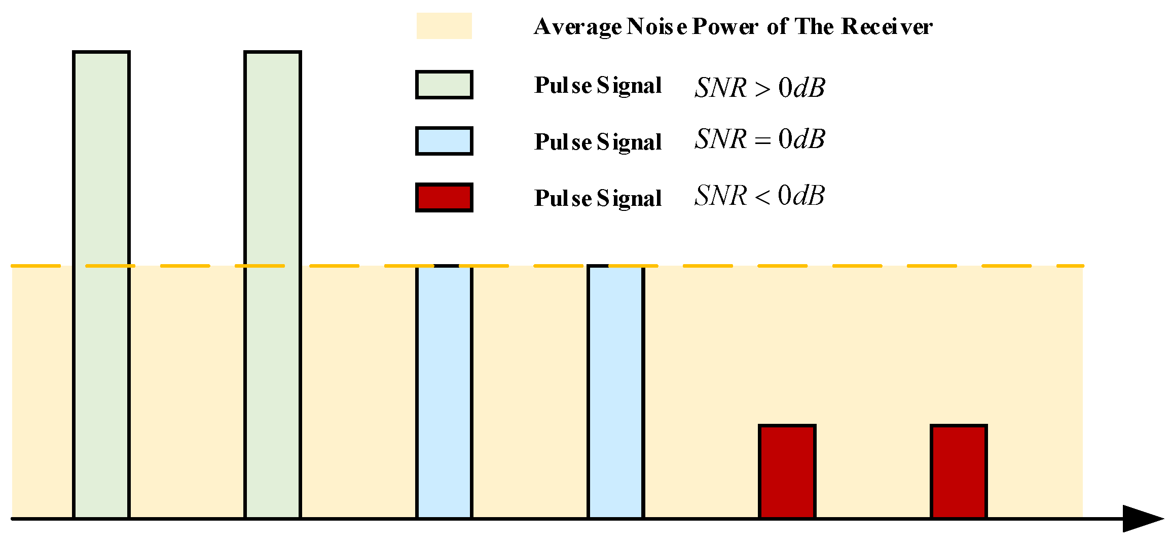
  • In this paper, a non-cooperative radar signal detection and high-quality pulse signal extraction algorithm based on PSO is developed, which can work under pulse interleaving with low SNR.
  • The radar signal deinterleaving is achieved by constructing a multi-layer PSO model with good robustness at low SNR. The proposed algorithm can accurately identify and separate the signals from different radar sources and is not sensitive to leakage pulses and false alarms.
The remaining parts of this paper proceed as follows. The radar electronic reconnaissance received signal model is shown in Section 2. Additionally, the problems of interleaved bursts and low SNR conditions for pulse signal acquisition are also formulated in this section. Then, the proposed multi-layer PSO algorithm is described in detail in Section 3. The effectiveness and robustness of the proposed algorithm are confirmed by the simulation experiments in Section 4. Finally, the application issues of the algorithm are covered and discussed in Section 5, and the article is summarized in Section 6.

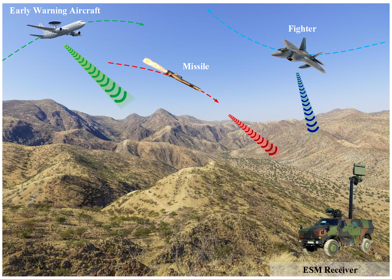
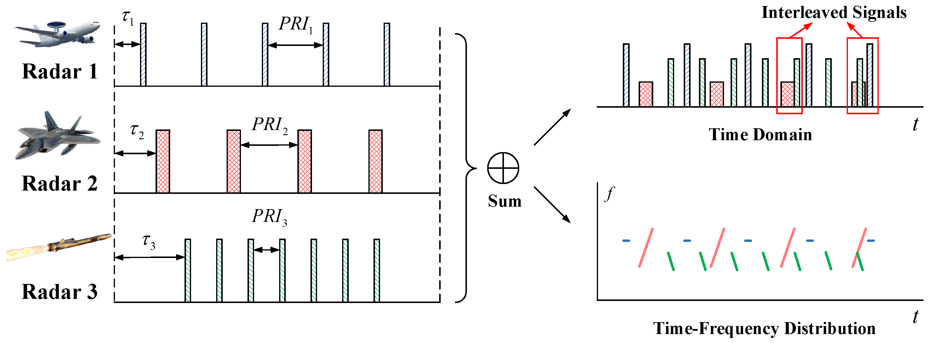
2. Reconnaissance Model and Problem Formulation

In the actual battlefield environment, in order to obtain enough electronic information, the ESM receiver is meant to receive and process signals from multiple radiation sources. An example reconnaissance model is shown in Figure 1. In this scenario, there is an ESM receiver on the ground, and there are three different radiation sources in space. The ESM receiver can receive radar signals with wide beam and receiver bandwidth from different directions and frequencies.
In the ESM received data, the signal of the l-th radar can be expressed by Formula (1).
s l t = A l · k l = 1 N l r e c t t τ l k l 1 · T t p e j φ l t + n t
where A l is the amplitude of the received signal, which is assumed to be constant in the received data. k l represents the k l -th received pulse, and N l represents the number of all received pulses of radar l. τ l represents the initial delay for the signal of radar l to reach the receiver. t p is the pulse width (PW), T is the pulse repeat time (PRT), and φ l t is the modulation function of the waveform, n t is the noise of ESM receiver, r e c t · is the rectangular window function, which can be expressed as
r e c t x = 1 0 , , 0 < x 1 o t h e r w i s e
For different radars, the parameters of the emission waveform will be different due to the various tasks performed. Nevertheless, these signals may still be interleaved after being received by ESM receiver. Figure 2 shows a situation where the radar waveform parameters differ, but the signals are still interleaved. This situation is not a particular case, but a situation that ESM often encounters at present. In this case, the pulse detected in the time domain may result from the superposition of signals from multiple radars. Or, in the frequency domain, some signals share the same spectrum and cannot be accurately separated. The large number of interleaved signals makes it hard for ESM to distinguish pulse signals from different radars, and the feature analysis of each radar can not be continued. Therefore, accurately separating these complex interleaved signals is a big problem ESM faces when acquiring information.
On the other hand, most of the signals caught up by reconnaissance equipment come from the side lobes of the radar beam, leading to low arrival power signals and poor SNR conditions. Furthermore, this situation will worsen due to the long transmission distance and the low-power modulation of LPI radar. Consequently, except for the signal interleaving, low SNR condition is another big problem for ESM. The low SNR of the received signal always bothers radar signal detection. As the SNR is defined in Formula (3), the signals under different SNR conditions are shown in Figure 3.
S N R = 10 lg P s P n
where P s is the average power of pulse signal and P n is the average power of noise.
As can be seen from Figure 3, when the SNR > 0 dB, the signal can be easily detected due to the higher power. The signal is nearly drowned out by noise when SNR ≤ 0 dB, which means the signal power is equal to or less than the noise power. In this instance, it is challenging to identify and extract the signal from the noise. Signal deinterleaving becomes hard to achieve if most of the signals are not reliably detectable. Furthermore, low SNR signals will also cause the accuracy of ESM’s signal feature extraction to decrease.
Therefore, in order to maintain the ESM’s ability to offer adequately accurate information support in the current electromagnetic environment where numerous radars coexist, it is required to overcome the problems of multiple radar signal interleaving and low SNR signal detection and extraction.

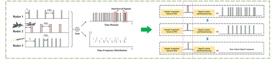
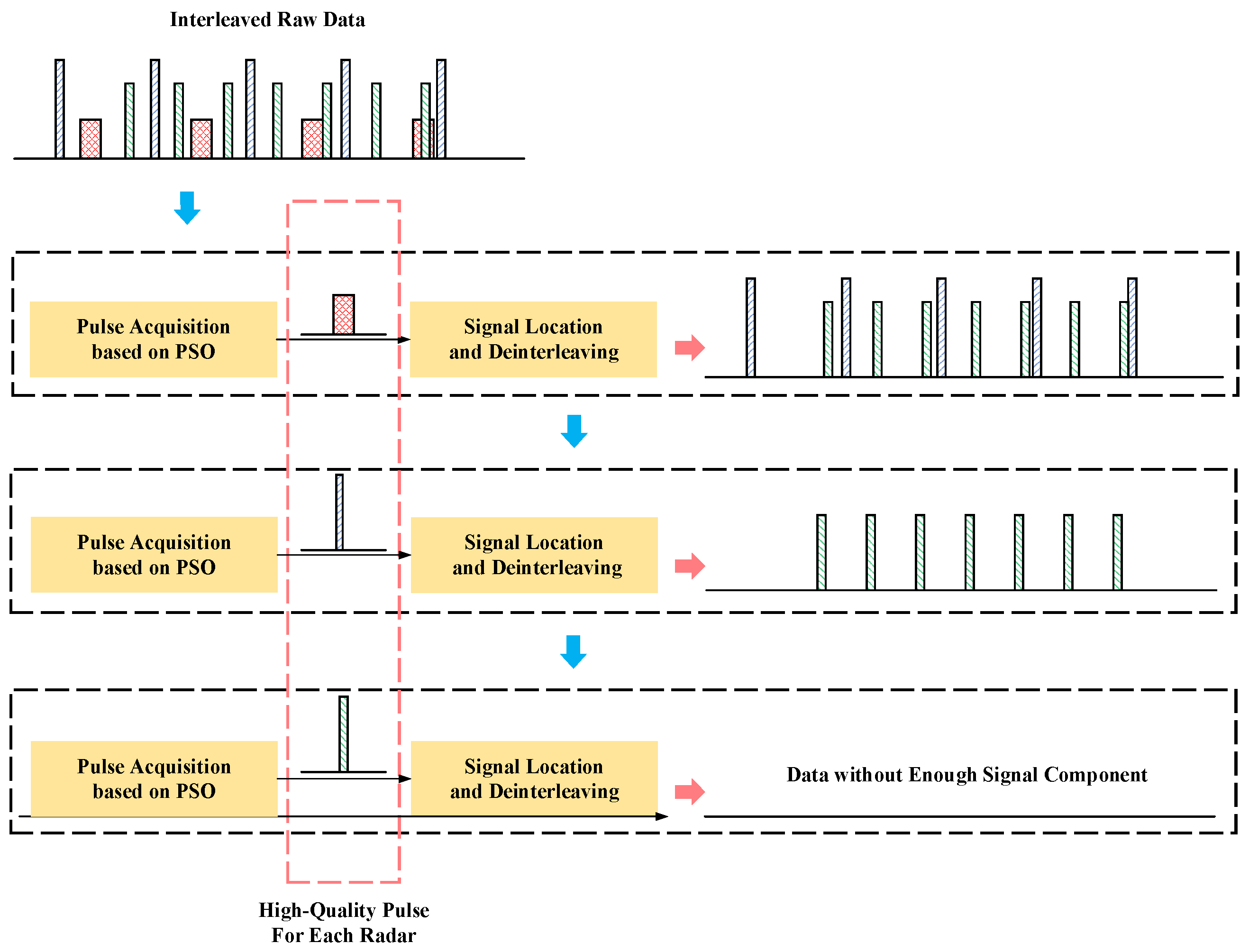
3. The Proposed Radar Pulse Signal Acquisition and Deinterleaving Algorithm

This section develops a high-quality pulse signal extraction and deinterleaving method based on multi-layer PSO to address the aforementioned issues. Figure 4 illustrates the algorithm’s block diagram. The suggested algorithm is divided into two primary parts. The PSO is presented in the first part for the optimal signal search, designed to extract the pulse signal through coherent accumulation. In the second part, the radar signals are deinterleaved from the interleaved raw data by locating and coherently canceling the radar signals according to the extracted pulse signal. With these two parts, building a multi-layer architecture, all radar signals in the received data can finally be deinterleaved, and their high-quality pulse signal can be obtained. The proposed technique performs well even in low SNR situations. The specific steps of the algorithm are shown as follows.

3.1. Blind Extraction of Pulse Signal Based on PSO

In the received data of ESM, radar signals interleaved and lacked prior information. Assuming that the SNR condition is good, radar signals can be detected in the time domain, while one detected pulse signal may be the interleaved result of several different radar signals, as Figure 2 shows. Thus, the detected result can not be used as a reliable data for feature analysis. If the SNR condition is poor, this situation will only get worse. Conventional radar signal detection methods are not applicable for pulse signal acquisition of interleaved signals.
Here, we propose a radar pulse signal extraction method from the interleaved data without any prior information. In practical applications, due to different work tasks and intentions, different radars transmit different waveforms to complete their respective functions. The mathematical expression of each radar-transmitted signal can be represented by Formula (4).
s t = A · r e c t t t p e j φ t
where A is the signal amplitude, and φ t is the phase modulation function of the signal.
For the received data, the waveform parameters of each radar can be regarded as unchanged in a very short period. Since the signals from the same radar have the same transmission waveform parameters, these signals are almost completely coherent after data alignment and phase compensation. With the coherency, the signal amplitudes can be accumulated by the in-phase addition, as shown in case 1 of Formula (5). Signals from different radars have different parameters, they can not be coherent even after data alignment and phase compensation. Their amplitude can hardly be improved by accumulation, and may even decrease, as in case 2 in Formula (5).
A m p = s t = A · r e c t t t p e j φ t = A A , , c a s e 1 c a s e 2
where φ t is the phase after compensation operation.
Since coherent waveforms can be accumulated to increase the amplitude to improve the SNR, this provides a way to obtain high-quality radar pulse signals. As shown in Figure 5, in a set of interleaved bursts, if the signals from the same radar can be grouped and aligned precisely, then they can be effectively accumulated to form a high-quality pulse signal of this radar. In this case, the acquisition of radar pulse signal can be transformed into an optimization problem for group, alignment, and accumulation of radar signals. As an easy-to-implement and parallelizable classic black-box optimization algorithm, the PSO algorithm is introduced to solve this problem. The optimization process is shown in Figure 6. In the proposed algorithm, the particle parameter is set as p = T w , T s , T e . T w is the group width, T s and T e are the start time and end time of the period for grouping the received data, respectively. The raw data are intercepted by T s and T e grouped by the width T w into M parts as Figure 5 shows before accumulation. M is calculated by Formula (6). It is almost impossible that T w happens to be the PRT of one radar, so the signals of these different groups cannot be directly superimposed to obtain a high SNR pulse, they should be aligned first. Alignment can be achieved by the cross-correlation function (CCF) between the groups. Each group may contain multiple signals from different radars, and there may be multiple peaks in CCF. Among these received signals, signals that come from the same radar with the greatest arrival energy will always contribute to a higher correlation; these signals are called principal component signal (PCS) in one-layer PSO. This means that when the PCSs are distributed in different groups, the maximum peak of CCF is always obtained by these signals from the same radar. According to the maximum peak in the CCF, the time offset can be calculated, and then these groups can be aligned after this offset is compensated. After data alignment, the phase in the data also needs to be compensated to ensure that the power or amplitude of these data is increased after superposition. With this accumulated data, the objective function under this particle parameter is calculated. If the convergence condition is not reached, then the particles will continue to be updated to obtain a better objective function. If it has converged, then this layer of PSO obtains an optimal particle parameter p = T w o p t , T s o p t , T e o p t . Finally, this optimal particle parameter is used to obtain high-quality pulse signals from raw data of this layer PSO. It should be noted that in one layer of PSO, only the PCS are distributed in different groups can the optimal objective function be obtained.
M = T e T s T w
where · is the operator that takes the floor constant.
The specific procedures of the proposed algorithm under one layer of PSO are described as follows.
First, take s i t from S as reference, and i = 1 by default. Then, in order to accumulate one optimal pulse signal, one pulse signal component should be time aligned between s i t and other parts s j t , j = 1 , 2 , 3 , M , j i . The PCS in s i t is represented by P C S i and the PCS in s j t is represented by P C S j . For P C S i and P C S j , they have the relationship shown in Equation (7).
P C S i t = P C S j t Δ t j
where Δ t j is the time offset of the two pulse signal component.
In order to achieve the alignment of PCS, this time offset Δ t j should be estimated according to the CCF of s i t and s j t , which can be calculated by Equation (8).
R i j τ = + s i t s j t τ d τ
where s j t is the conjugate of s j t .
When j = i , CCF R i j becomes auto-correlation function (ACF) R i i . The peak of ACF appears at t A C F = 0 because there is no time offset between P C S i and P C S i , while the highest peak in CCF appears at t C C F = τ , since there is time offset between P C S i and P C S j , and the time offset Δ t j = t C C F t A C F = τ .
Then, the alignment can be achieved by compensating the time offset according to the nature of the Fourier transform. A signal that has a temporal shift will have a phase shift in the Fourier transform output. Consequently, the phase-compensated s j t Fourier transform result with Δ t j can be used to produce the aligned signal by the inverse Fourier transform. This process can be expressed by Formula (9).
S j ω = F s j t S j ω = S j ω e j ω Δ t j s j t = F 1 S j ω
where F · is the Fast Fourier transform (FFT) operator, and F 1 · is the inverse Fast Fourier transform (IFFT) operator. s j t is the aligned signal of s j t . For convenience, the subsequent s j t defaults to the aligned signal.
When the PCSs in M parts have been time-aligned, optimal accumulation can be achieved after phase compensation, since the phase φ j of signal s j t is usually inconsistent with the reference signal phase φ j . Here, the phase estimation and compensation are performed for each group signal s j t according to Equations (10) and (11).
Δ φ = P H s i t · s j t = φ i φ j
s j t = s j t · e j Δ φ = A e j φ j + Δ φ + n t = A e j φ i + n t
where P H · is the phase operator and s j t is the phase compensated signal.
Finally, the group signal S = s 1 t , s 2 t , s m t , , s M t is aligned and phase compensated to a new group signal S = s 1 t , s 2 t , s m t , , s M t . In this case, the group signals obtained by particle parameter p can be accumulated coherently for pulse signal acquisition. The pulse signal can be expressed as follows:
s a t = m = 1 M s m t
In order to obtain the optimal pulse signal, a convergent objective function should be designed in the PSO algorithm to facilitate continuous iteration of particles, which is shown in (13).
f o b j p = w 1 · S N R A A + w 2 · A A E w 3 · E C
where w 1 , w 2 , w 3 are the weights of each indicator, S N R A A is the SNR after accumulation, A A E is the average accumulation efficiency, and E C is the energy aggregation. They are three indicators based on the obtained pulse signal quality for constructing the effective objective function.
Here is the definition of the three indicators. S N R A A is the ratio of the peak power and the noise power of the accumulated signal s a t , which can be calculated by (14). The larger it is, the better the accumulated performance. However, since it is only a rough estimate, the accumulation under some special circumstances can also reach a relatively high S N R A A . For example, when the reciprocal of the group width 1 1 T w T w is the harmonic of the pulse repetition frequency (PRF), one pulse signal may be divided into multiple parts. Groups data with the same pulse components will still be accumulated, and the finally obtain a relatively high S N R A A . In this case, there must be some groups that do not contain effective signal components, and these groups do not contribute to S N R A A . According to this feature, A A E is introduced to represent the contribution of each group of data to the improvement in the accumulated SNR, which is defined as (15). The adoption of A A E aids in preventing the PSO algorithm from being entangled in the PRF harmonic component local optimization. On the other hand, if T w is too large in PSO, multiple pulse signals will appear in each group of data. The accumulated signal should ideally contain only one pulse. Therefore, E C is used to avoid this multiple pulse signals situation, which is defined in (16). These above three parameters can ensure that the PSO obtains an ideal pulse signal as much as possible.
S N R A A = 10 lg P s e P n e
A A E = S N R A A M
E C = 0 1 , n = 1 e l s e
where P s e is the estimated signal power in the accumulated signal, which is the mean power of the first D points after the power is sorted in descending order (in the experiment in Section 4, D = 200 ). P n e is the estimated noise power in the accumulated signal, which is obtained by the median of power. n is the detected pulse number in the accumulated signal.
With the signal accumulation method and objective function, PSO can obtain a high-quality pulse signal in an interleaved burst. Here, it also gives two critical update equations of the particle parameters, and the specific steps of the algorithm are summarized in Algorithm 1.
x k = x k + v k
v k = ω · v k + c 1 · r a n d · × p b e s t k x k + c 2 · r a n d · × g b e s t k x k
where x k is the particle position, which is p = T w , T s , T e in the proposed algorithm, v k is the particle velocity, ω is the inertial factor of particle motion, ω 0 . The linear decreasing weight strategy is used to set this parameter here. c 1 and c 2 are called learning factors, usually c 1 = c 2 = 2 . And r a n d · represents a random matrix.
Algorithm 1: High-quality pulse signal acquisition based on PSO algorithm
Input: The received interleaved signal f t = s l t .
Step 1: Initialize particle parameter p = T w 0 , T s 0 , T e 0 .
Step 2: Grouping and accumulating the signal with particle parameter according to Equations from (6) to (12).
Step 3: Based on the accumulated data, calculating the objective function according to (13).
Step 4: Evaluate the objective function of the current particle parameter p and its optimal parameter p b e s t and update p b e s t .
Step 5: Evaluate the objective function of the current particle parameter p and the global optimal parameter g b e s t and update g b e s t .
Step 6: Update the particle position and velocity according to (17) and (18).
Step 7: Repeat step 2 to step 6 until the maximum number of iterations or reach the objective function threshold.
Output: The optimal particle parameter p = T w o p t , T s o p t , T e o p t and high-quality radar pulse signal s H Q t .

3.2. Multi-Layer PSO for Pulse Deinterleaving

Section 3.1 proposed a pulse signal acquisition algorithm based on PSO, while one layer PSO can only obtain one radar’s pulse signal, usually the one with optimal SNR after accumulation. In order to deinterleave all the radar signals from the received burst, a multi-layer PSO framework is built with iterative extraction and elimination operations, which are shown in Figure 4. Supposing that there are several radars’ signals in the received signal f t = s l t , and one radars’ pulse signal has been obtained by Algorithm 1 with the input f t . The specific procedures for signal deinterleaving and other radar high-quality pulse signal acquiring based on the multi-layer framework are concluded as follows.
When the signal of one radar has been extracted, it needs to be separated from the received signal f t to complete the deinterleaving of the signal. Here, we propose a deinterleave approach based on MF and coherent cancellation.
Take the obtained pulse signal s H Q t as a reference signal to construct MF, which is expressed as Formula (19).
h t = s H Q T r t
where s H Q · is the conjugate of s H Q · and T r is the time width of s H Q t .
Let the received signal f t be input into the filter h t , the MF can be achieved by (20).
g t = f t h t
where ⊗ represents the convolution operator.
Since the convolution of the time domain is the multiplication of the frequency domain, the MF can be accomplished faster by transforming Formula (20) into Formula (21).
g t = F 1 F j ω · H j ω
where F j ω = F f t and H j ω = F h t .
The result of MF will form significant peaks at the signal position that have strong coherent relationship with the reference signal. Assuming that the pulses of the radar corresponding to the current pulse s H Q t are uniform, then the peak positions can be expressed as (22). The signals from the same radar source are located by the peaks in the MF result.
p o s = k = 1 N δ t τ 0 k 1 T r
where τ 0 represents the initial delay for the signal to reach the receiver, k represents the k-th peak, and there are N peaks.
Additionally, the power of the signal from the same radar is generally the same due to the same transmission distance and channel characteristics. In this case, each received signal of this radar can be modulated by s H Q t , as shown in Formula (23).
s k t = 1 M s H Q t e j Δ φ k
where k = 1 , 2 , 3 , , N is the index of the received signal from this radar source, and Δ φ k is the phase difference between the real signal and the estimated pulse signal.
Then, all pulse signals from this radar can be suppressed from the received data f t through Formulas (22) and (23). The suppression can be expressed as
f t = f t p o s , s k t = f t k = 1 N r e c t t τ 0 k 1 T r T r 1 M s H Q t e j Δ φ k
where p o s , s k t means that the pulse signal is used at each signal location to modulate and reconstruct the original signal.
After the suppression, signals from one particular radar source are deinterleaved from the received signal f t . Only the signal components of other radars are retained now. Therefore, f t can be updated by f t and entered into the next layer PSO. In the next layer, Algorithms 1 and 2 are re-performed for signal pulse signal acquisition and deinterleaving from the received data. This iterative multi-layer structure will continue to be executed until f t no longer contains any radar signal components or the signal components have been suppressed to a low enough level. In this case, it is hard to achieve effective accumulation when executing Algorithm 1. Without good accumulation results, S N R A A and A A E in the objective function f o b j become small, while false alarms cause E C = 1 , which eventually leads to the objective function f o b j > 0 . Therefore, in the proposed algorithm, f o b j > 0 is set as the criterion for terminating multi-layer PSO iteration.
In this multi-layer PSO algorithm, the signals of each radar are sequentially deinterleaved from the original received signals, and the high-quality pulse signals of each radar are obtained. These high-quality pulse signals can be used for subsequent radar signal parameter estimation, allowing ESM to provide more accurate intelligence information for jammers in multi-radar sources and low SNR environments.
Algorithm 2: signal deinterleaving under multi-layer PSO
Input: The high quality pulse signal s H Q t obtained by Algorithm 1.
Step 1: Construct matching filter based on s H Q t according to Equation (19).
Step 2: Signals from the same radar source are located by (22).
Step 3: All the pulse signals are deinterleaved from the received signal f t according to (24).
Step 4: Update f t and enter into the next layer PSO.
Step 5: Re-perform Algorithm 1 and repeat Step 1 to Step 4 until f o b j < 0 .
Step 6: Update the particle position and velocity according to (17) and (18).
Output: All the radar source signals are deinterleaved from f t and the high-quality radar pulse signal of each radar source.

4. Experiments

Experiments are carried out to demonstrate the efficacy of this proposed method for radar pulse signal acquisition and deinterleaving. First and foremost, the effectiveness of radar signal deinterleaving and pulse signal acquisition have been experimentally validated. Second, other signal detection methods are used to compare and examine the advantages of the proposed radar signal detection and extraction method. Finally, the advantages of the proposed algorithm in deinterleaving are also demonstrated. The above experiments illustrate the effectiveness and robustness of the proposed signal detection and deinterleaving algorithm.

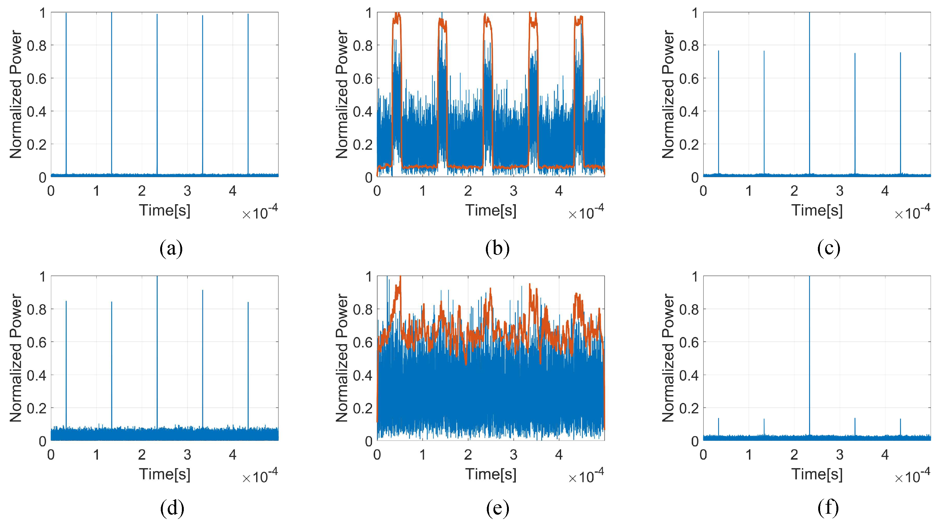
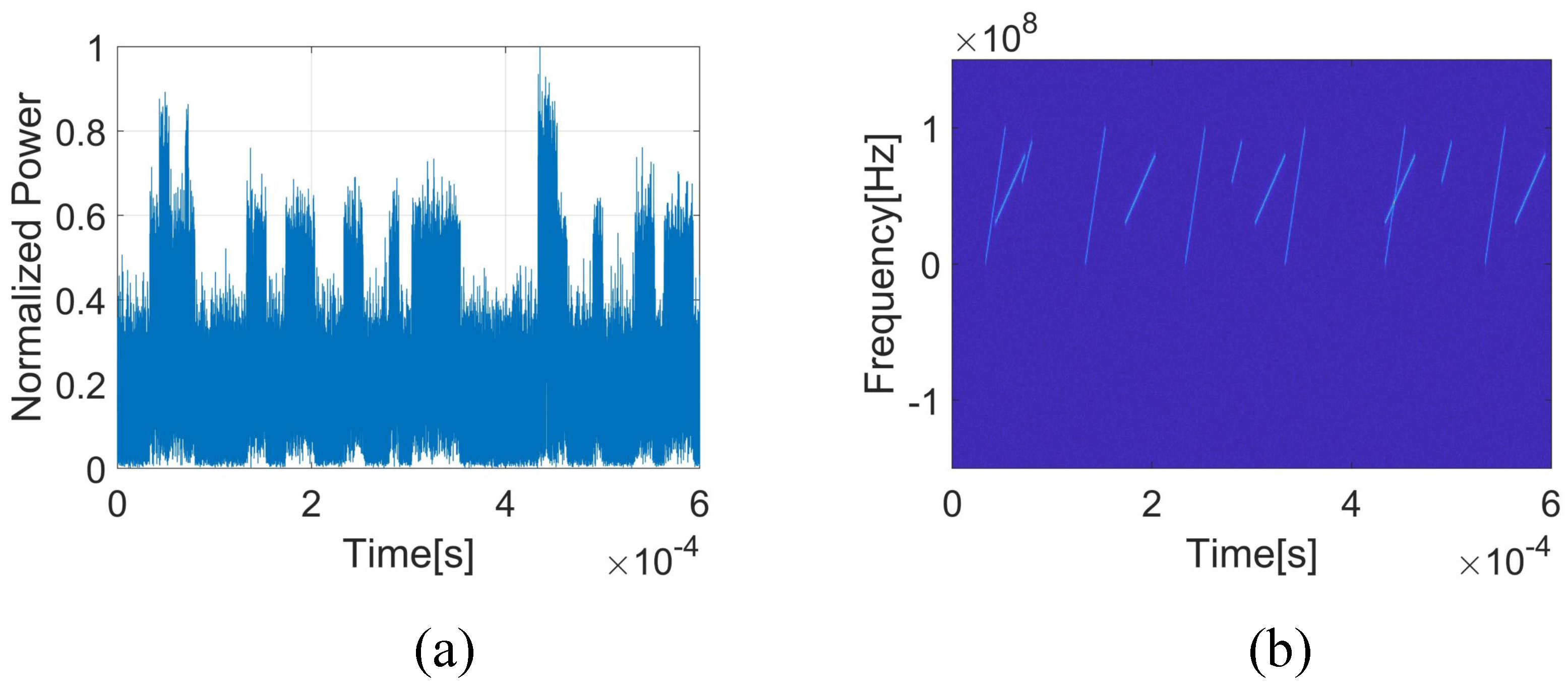
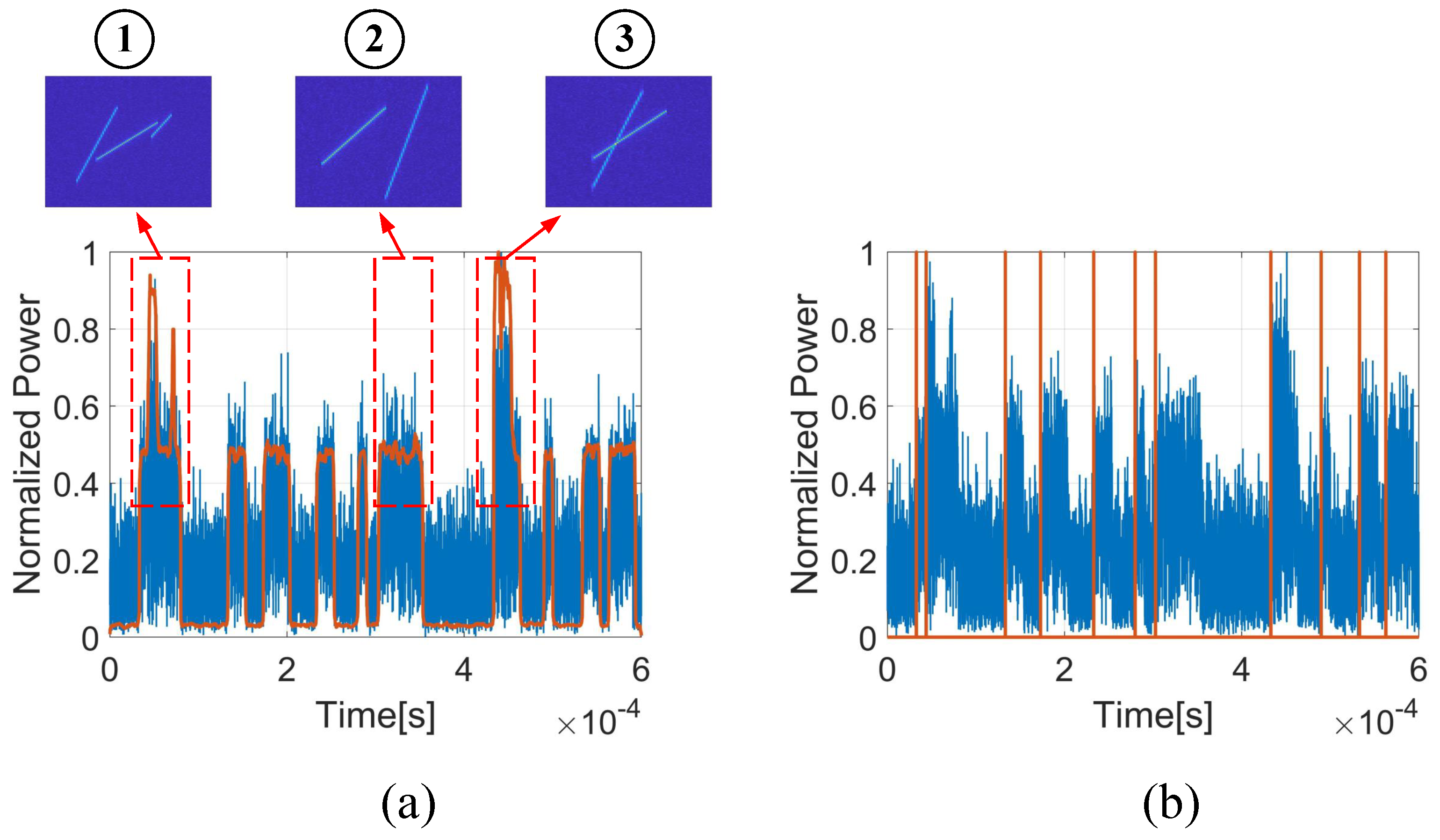
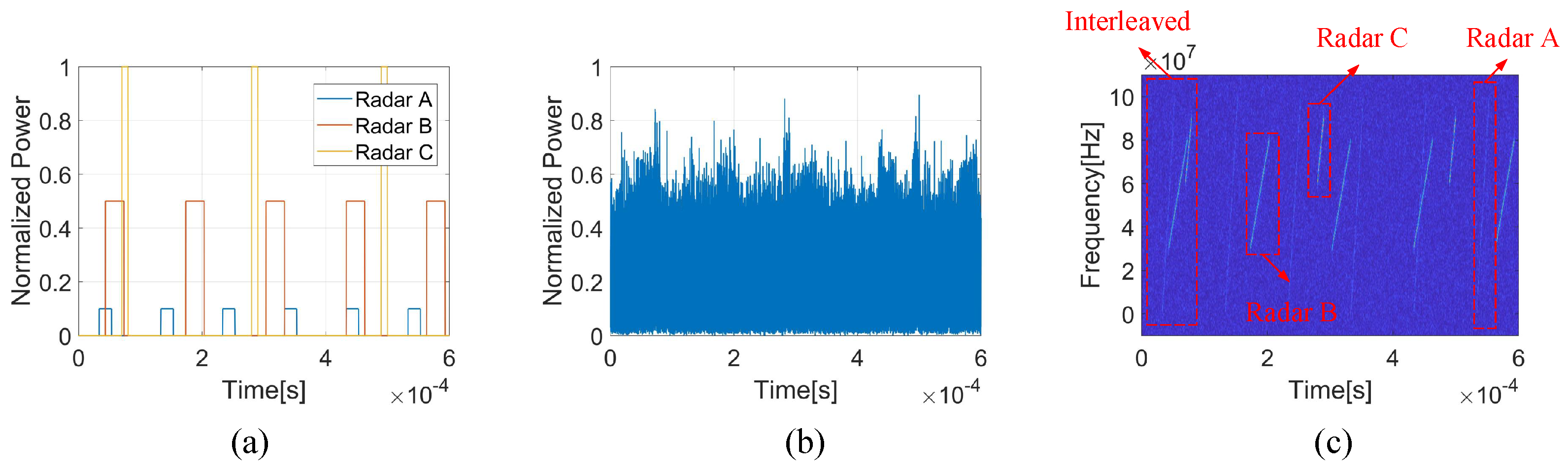
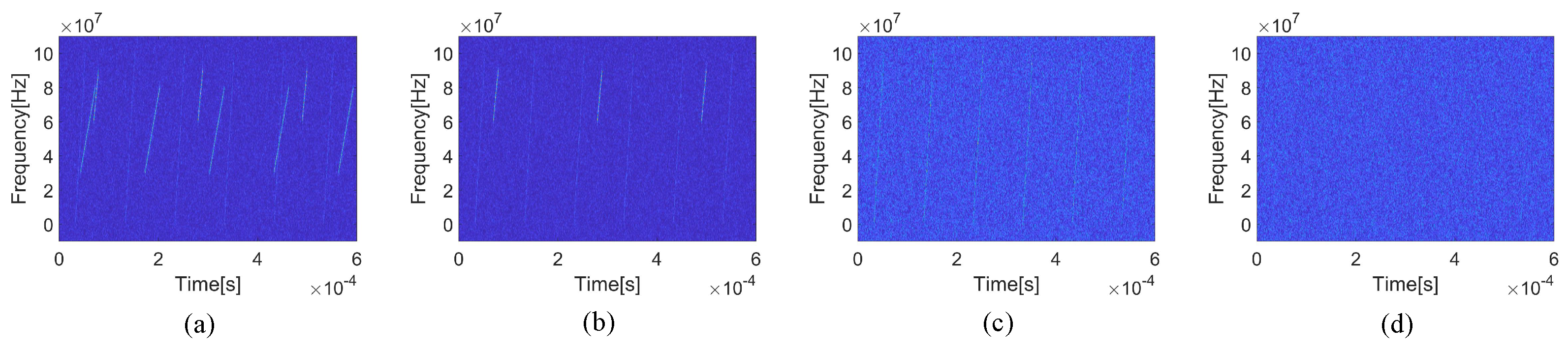
4.1. Signal Extraction for Multi-Radar Sources under Low SNR

Supposing there are three radar sources, like the scene in Figure 1; their waveform parameters are shown in Table 1. The ESM receiver receives the three radars’ signals, and there are 50 signals from Radar A, 50 signals from Radar B, and 30 signals from Radar C. Some of the simulated signals are shown in Figure 7. Figure 7a is the pure signals from different radars without noise, the overlap relationship of these signals are displayed in it. The interleaved signals with noise in ESM receiver are shown in Figure 7b, and their time-frequency distribution (TFD) obtained by short time Fourier transform (STFT) is shown in Figure 7c. Although the signals of these radars have different waveform parameters, when they reach the same receiver, the time and frequency of the signals may still overlap, resulting in signal interleaving, as shown in Figure 7b. Moreover, due to factors such as the long transmission distance and the low peak power of the LPI radar, the SNR of these reaching signals in the receiver may be too low to detect signals, as shown in Figure 7a. The interleaved signal and the low SNR would degrade the radar signal detection performance.
As the radar signals are interleaved in the ESM receiver with a low SNR condition, only the signals of each different radar can be extracted and deinterleaved from the received data can the ESM provide accurate intelligence information for subsequent operations. In this experiment, the proposed multi-layer PSO is used to deinterleave these radar signals and extract these radar sources’ pulse signals. The deinterleaving process is shown in Figure 8, and the extracted high-quality pulse signals are shown in Figure 9. For each layer of PSO, 30 iterations are executed.
In order to facilitate the display of experimental results, signals’ TFD in each layer PSO are shown in Figure 8. First, the initial ESM received signal Figure 8a is used as input the proposed multi-layer PSO. In the first layer PSO, particle parameters are used to group, align, phase compensate, and accumulate the data in Figure 8a to obtain an optimal pulse signals, which are shown in Figure 9b,e. This signal from Radar B is first extracted. Then, these signals from the same radar as the extracted signal are suppressed from Figure 8a, and the output result of this layer of PSO was obtained in Figure 8b. As the input of the second layer PSO, the PSO extracts the Radar C pulse signal shown in Figure 9c,f from the data in Figure 8b. Finally, the pulse signal from Radar A is also extracted from Figure 8c, as shown in Figure 9a,d. After the three-layer PSO in Figure 8d, there is almost no radar signal component in the received data, which makes the objective function f o b j > 0 of the next layer PSO. At this point, the execution of the proposed algorithm is terminated. It deinterleaves all the signals of the three radars from the original received signals and extracts the higher SNR pulse signal of each radar, as shown in Figure 9.
Figure 9a–c are the high-quality pulse signal of Radar A, B, and C, respectively. Figure 9d–f are their corresponding TFD. Apparently, SNR > 0 in the acquired pulse signals, and it is easy to estimate the radar signal parameters. Here, we calculate the parameters of the pulse based on the TFD of the extracted pulse signal. For the three radars, their PW are 20.48 µs 29.87 µs, 10.24 µs, band width (BW) are 97.2 7 MHz, 48.63 MHz, 28.13 MHz and center frequency are 50.39 MHz, 55.37 MHz, 75.59 MHz. Comparing the simulated parameters in Table 1, the maximum frequency domain parameter error is less than 3 MHz, and the time domain parameter error is less than 1 µs. Without any improved parameter estimation method, this accuracy is sufficient to prove the good quality of the pulse signals extracted by the proposed algorithm.
According to the above experimental results, it can be fully proved that the proposed multi-layer PSO algorithm can effectively separate the signals of each radar source from the interleaved bursts with low SNR conditions and obtain their high-quality pulse signals.

4.2. Robust Performance Compared to Conventional Algorithms

Acquiring a high-quality pulse signal is essential for radar reconnaissance signal processing. Accurate pulse signal acquisition is a necessary prerequisite for subsequent radar waveform feature estimation. Generally speaking, the acquisition of pulse signal is realized based on signal detection. Reference [18] proposes a shifted-N points-correlation algorithm (SNCA) for non-cooperative target signal detection that can obtain the temporal location of weak signals with unknown parameters. A radar pulse signal can be obtained for subsequent processes based on the detected signal locations. Additionally, another pulse signal extraction algorithm based on segment autocorrelation (SAC) is proposed in [25]. While the proposed algorithm can achieve high-quality pulse signal extraction before signal detection, compared with the conventional algorithms, the pulse signal quality extracted by the proposed algorithm does not depend on the performance of signal detection. In this section, some comparative experiments are designed to verify the superiority of the proposed algorithm in pulse signal extraction.

4.2.1. Signals from One Radar Source

Assume that the received signals are only from one radar source, like the fundamental model in conventional algorithms. In this experiment, the radar source is Radar A in Table 1, while its SNR is set into two values here, respectively. One is SNR = 8 dB, and another is SNR = 5 dB. SNR = 5 dB is usually considered a good condition for reconnaissance signal detection, while SNR = 8 dB is not. The simulated signals under different SNR conditions are shown in Figure 10. For convenience, only five pulses are shown here. When SNR = 5 dB, the pulse signal and noise are easy to identify. While when SNR = 8 dB, the pulse signal has been completely submerged in the noise. In this case, locating and extracting the pulse signals is impossible.
With these two SNR conditions, the proposed algorithms, SNCA and SAC, are used to locate and extract these signals. The three algorithms’ results are shown in Figure 11, and only five pulses’ location results are displayed here for convenience. For Figure 11b,e, the blue is the simulated data and the red is the obtained envelope by SNCA. Additionally, the PRT, pw, bw, and center frequency of the signals are also estimated to illustrate the performance of the three algorithms under different SNR conditions.
According to the positioning results, each algorithm performs well in a good SNR environment. The proposed algorithm and the SAC algorithm have a similar positioning mechanism, their positioning results are very similar, and the positioning peaks obtained by the proposed algorithm are more uniform. Since the SAC algorithm adopts one segment to calculate the correlation function, the peaks obtained are significantly different, and the selected segment can obtain the highest positioning peak. There will be some performance loss in the cross-correlation between other signals and the segment. SNCA realizes pulse detection by accumulating in the pulse to obtain an envelope with a higher SNR. At SNR = 5 dB, the envelope SNR is significantly improved. With good positioning results, pulse signals are extracted for parameter estimation. For multi-layer PSO, SNCA, and SAC algorithms, the estimated PRT are 100.01 µs, 99.97 µs, and 100.01 µs, respectively. High-precision detection and positioning have been proved by the estimated PRT. Additionally, the estimated bw are 97.27 MHz, 94.04 MHz and 95.32 MHz, the estimated center frequency are 50.01 MHz, 49.37 MHz and 50.24 MHz, the estimated pw are 20.15 µs, 19.63 µs and 19.82 µs. With the same parameter estimation method, the parameter estimation accuracy of the pulse signals extracted by the proposed algorithm is higher than the other two algorithms.
When SNR = 8 dB, the performance of the SCNA and SAC algorithms suffers a severe loss. As shown in Figure 11e, the accumulated signal envelope also deteriorates due to the poor SNR in the initial signal. With this envelope, it is almost impossible to distinguish the specific location of the pulse signal from the noise. As for the SAC algorithm, the greater noise power further exacerbates the cross-correlation loss of selected segment and other signals, that makes there is only one significant peak in Figure 11f. The peaks of other pulses are too low to detect, and the signal location can not be achieved in this case. Due to the failure of signal location, neither the SCNA nor the SAC algorithm can extract the pulse signal of the radar source. Consequently, waveform parameters and other information estimation are also impossible to achieve. Unlike these two algorithms, the proposed multi-layer PSO algorithm extracts the pulse signal before location. Then, the pulse signal is used to locate the signals as shown in Formula (22), and the location result with good performance is shown in Figure 11d. Additionally, the estimated PRT, pw, bw, and center frequencies are 100.01 µs, 19.62 µs, 94.33 MHz, and 50.97 MHz, respectively. Compared with the parameter estimation result at SNR = 5 dB, the accuracy of the parameter estimation result at SNR = 8 dB has almost no performance loss.
According to the above experimental result and analysis, the proposed multi-layer PSO algorithm displays good robustness under different SNRs, and it does not depend on the detection performance; it is very suitable for applications in the real world, which is usually troubled by low SNRs.

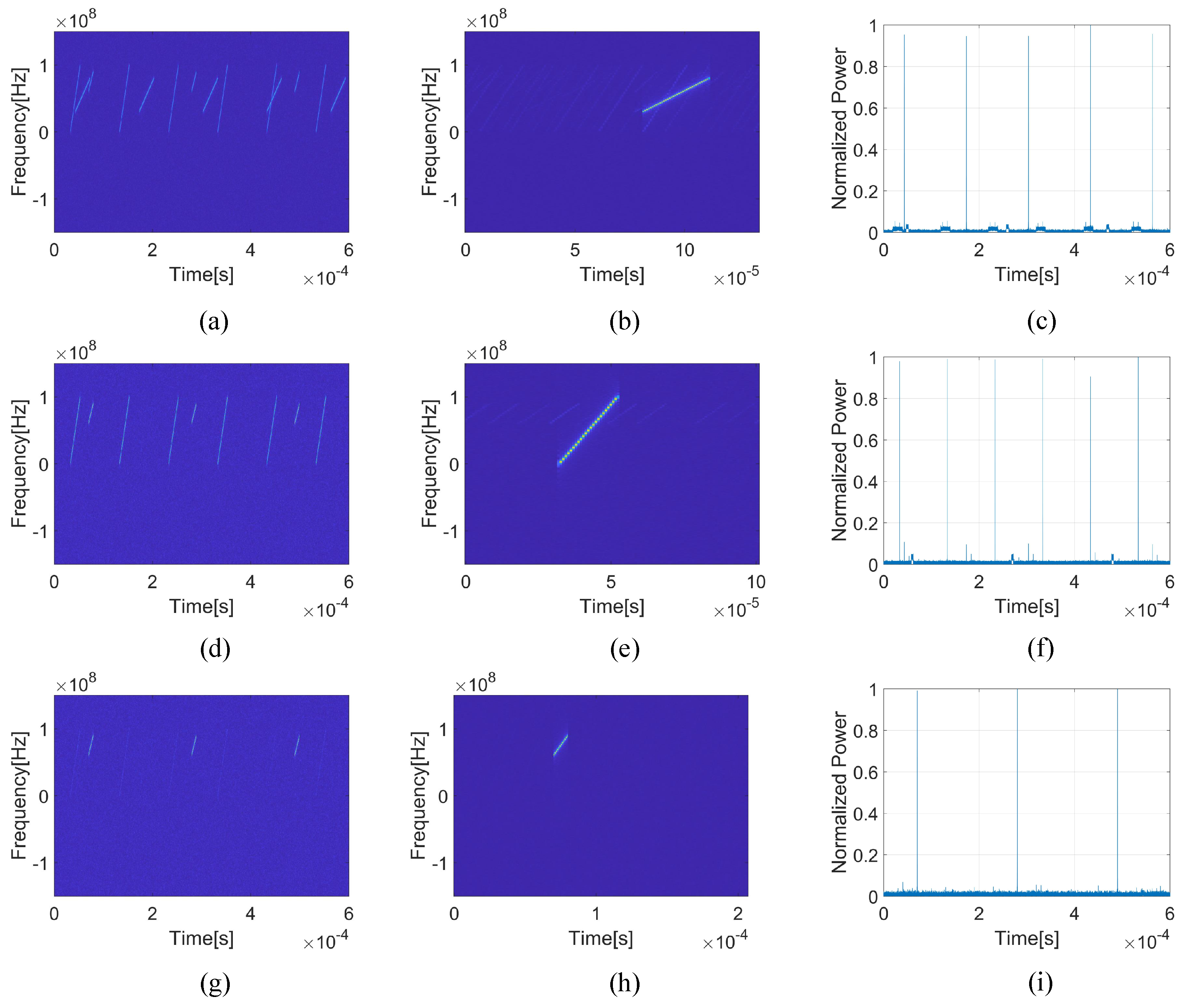
4.2.2. Signals from Multiple Radar Sources

In practical applications, not only is SNR bothering the processing and analysis of radar electronic reconnaissance signals, but interleaved bursts from multiple radar sources are also a significant problem. To further illustrate the advantages of the proposed algorithm over conventional algorithms, the other two radars in Table 1 have also been reintroduced into the experiments in this section. The waveform parameters of radar A, B, and C remain unchanged, and their SNRs are uniformly set to 5 dB to avoid the impact of noise on signal detection. The simulated signals from three radar sources and their TFD are shown in Figure 12. For convenience, only part of the signals are displayed here.
As shown in Figure 12, signals from three radar sources are interleaved in the received data. In order to achieve effective ESM, deinterleaving these signals is necessary. Usually, deinterleaving is achieved by searching for different PRI based on the signal TOA. TOA is the signal temporal location result. For comparison, the SCNA is used for signal detection, the accumulated envelope is fed into a constant false alarm rate (CFAR) detector to obtain the TOA of pulse signals, then the SDIF algorithm is performed here to deinterleave these signals. The experimental results are shown in Figure 13, the blue is the simulated data, the red in Figure 13a is the obtained envelope by SCNA and the red in Figure 13b is the detected TOA. In (a), the good envelope has been obtained by SCNA, which is beneficial for TOA detection. However, there are some signals from different radar sources that overlap in the time domain, which are marked as ①, ②, and ③. Although their envelopes have been accumulated, the CFAR detector cannot detect TOA where there is no significant difference in the envelopes. Thus, some signals’ TOA are destined to be lost, which is shown in Figure 13b. With these large numbers of lost TOAs, it is difficult for the SDIF algorithm to find continuous pulses with the same PRI through a multi-stage TOA differential. In this experiment, the SDIF algorithm failed to deinterleave. It failed to accurately identify different PRIs, let alone the number of different radar sources and their signals.
On the other hand, the proposed multi-layer PSO algorithm is also used to deinterleave these signals, and its experimental results are shown in Figure 14. First, the simulated signals with multiple radar sources are the input to the proposed algorithm. After the first layer PSO, one radar pulse signal is obtained, as shown in Figure 14b. According to its TFD, this pulse signal is from Radar B, and its location results are shown in Figure 14c. By comparing (a) and (c) of Figure 14, it can be seen that these positioning results are accurate. The PRI of Radar B can be estimated by these location results; that is, 129.9 µs, the estimated error less than 0.1 µs. Then, the signals from Radar B are coherently canceled from the interleaved data and as the input for the next layer, as shown in Figure 14d. Finally, with the obtained radar pulse signals and their locations, the deinterleaving of these radar source signals is achieved.
According to the above experimental results, the conventional deinterleaving algorithm depends on the signal TOA detection performance. In the modern electromagnetic confrontation environment, many signals from different radar sources overlap, leading to some signal TOA detection failure. Then, these lost TOAs further degrade the performance of conventional deinterleaving algorithms, which makes them unable to acquire the number and the value of different radar PRIs. Without accurate PRIs, the deinterleaving of conventional algorithms will fail, and this interleaved burst can not be used for information extraction of the ESM. Since this overlap phenomenon is common in real-world applications, conventional algorithms are currently limited. On the other hand, the proposed multi-layer PSO algorithm is not affected by the signal detection performance. Additionally, it can simultaneously deinterleave the signals of each radar source and obtain the corresponding high-quality pulse signal. The proposed algorithm shows more robust performance in the face of low SNR conditions and multiple radar sources, and it has better practical application prospects and value.

5. Discussion

Some application issues have been discussed here to improve the implementation of the proposed algorithm.
The LFM waveform, as a classic LPI radar waveform, is used as the default radar waveform in this paper to illustrate and verify the algorithm. Of course, the proposed algorithm is not limited to only LFM waveform. The proposed algorithm is achieved by the coherent waveform of the same radar source. All the waveforms with the same parameter can be accumulated coherently, which makes our proposed algorithm effective. Thus, the proposed algorithm can be applied to all radar waveforms in theory. It should be noted that when the radar transmission waveform is single-frequency signal, the location of the signal should be achieved by CCF instead of MF.
On the other hand, compared with conventional algorithms, the proposed multi-layer PSO algorithm brings a greater computational burden. This is one disadvantage of the proposed algorithm. It may take longer to deinterleave the received signals and extract pulse signal from each radar source. For example, in the experiment in this paper, a computer with eight threads and 48 GB of RAM takes about 10 to 15 min to implement the proposed algorithm. Although there is some computational burden, the accuracy and robustness of the proposed algorithm are unmatched by conventional algorithms. Sometimes, the accuracy of information is more important than speed in ESM. Fortunately, with the continuous development of hardware equipment and the introduction of multi-threaded computing, the computational efficiency of the proposed algorithm will be effectively improved. The proposed algorithm will have good application prospects in future digital signal processing equipment.
The application SNR lower bound of the proposed algorithm is related to the time width t p of the target radar waveform. Since CCF is required to align the signal in the proposed algorithm, the peak detection of CCF is related to the application performance of the proposed algorithm. The SNR of the signal CCF can be expressed as
S N = E N 0 = s t 2 d t σ n 4 = P s · t p σ n 2 · σ n 2 = S N 0 · t p σ n 2
When the SNR of CCF is ≥13 dB, it is conducive to its peak detection. Then, if the time width t p of the transmitted signal is greater, the lower the initial SNR that the proposed algorithm can cope with. Therefore, the lower bound of the application SNR of the proposed algorithm varies according to the pulse width emitted by the target radar source.
Last but not least, the SNR of the final acquired pulse signal depends on the number of received pulses and the initial SNR.

6. Conclusions

With the development of radar equipment, the current electromagnetic environment is becoming more and more crowded. In addition, the application of LPI radar and the long-distance transmission of signals make the signal SNR reaching the ESM receiver very poor. In order to improve the performance of deinterleaving and signal extraction, a multi-layer PSO algorithm has been proposed in this paper. Without any a priori information, PSO is used to search for the optimal radar pulse signal iteratively. Then, this radar source’s signals are located and deinterleaved based on the extracted pulse signal. The multi-layer architecture realizes the pulse signal extraction and deinterleaving of signals from different radar sources. Experiments have proved that the proposed algorithm can extract signals from different radar sources under low SNR conditions and realize their deinterleaving. Moreover, it can still maintain good performance, even if conventional algorithms fail. The proposed algorithm extracts pulse signals before signal detection, which makes it more suitable for real-world applications.

Author Contributions

S.W., conceptualization, investigation, methodology, writing—original draft preparation, validation and formal analysis; Y.F., investigation, methodology, writing—review and editing; C.H., investigation, validation; L.Z., conceptualization, methodology, funding acquisition. All authors have read and agreed to the published version of the manuscript.

Funding

This work was supported in part by the National Natural Science Foundation of China under Grant 62201623, 62101603, 62371446.

Data Availability Statement

Data is simulated by the proposed parameters in this paper.

Acknowledgments

The authors would like to thank the anonymous reviewers for their valuable comments that improved the quality of this article.

Conflicts of Interest

The authors declare no conflicts of interest.

References

  1. Schroer, R. Electronic warfare. [A century of powered flight: 1903–2003]. IEEE Aerosp. Electron. Syst. Mag. 2003, 18, 49–54. [Google Scholar] [CrossRef]
  2. Benren, T. An ECCM model and the technical development trends to the demands of the future EW combat. IEEE Aerosp. Electron. Syst. Mag. 1994, 9, 12–16. [Google Scholar] [CrossRef]
  3. Wang, G.; He, Y.; Shen, N.; Lu, D.; Yan, H. A new radar-ESM correlation algorithm in multisensor data fusion. In Proceedings of the International Radar Conference, Beijing, China, 8–10 October 1996; pp. 747–750. [Google Scholar] [CrossRef]
  4. Matthes, D. Convergence of ESM sensors and passive covert radar. In Proceedings of the IEEE International Radar Conference, Arlington, VA, USA, 9–12 May 2005; pp. 430–444. [Google Scholar] [CrossRef]
  5. Pietkiewicz, T. Fusion of Identification Information from ESM Sensors and Radars Using Dezert–Smarandache Theory Rules. Remote Sens. 2023, 15, 3977. [Google Scholar] [CrossRef]
  6. Zhou, S.; Zhang, Y.; Ma, H.; Peng, X.; Yang, D.; Liu, H.; Yan, J. Optimized Masking for MIMO Radar Signals. IEEE Trans. Aerosp. Electron. Syst. 2021, 57, 3433–3451. [Google Scholar] [CrossRef]
  7. Li, X.; Liu, Z.; Huang, Z.; Liu, W. Radar Emitter Classification with Attention-Based Multi-RNNs. IEEE Commun. Lett. 2020, 24, 2000–2004. [Google Scholar] [CrossRef]
  8. Xu, T.; Yuan, S.; Liu, Z.; Guo, F. Radar Emitter Recognition Based on Parameter Set Clustering and Classification. Remote Sens. 2022, 14, 4468. [Google Scholar] [CrossRef]
  9. Whalley, G.W. Signal processing requirements for future ESM systems. In Proceedings of the IEE Colloquium on Signal Processing for ESM Systems, London, UK, 26 April 1988; pp. 2/1–2/4. [Google Scholar]
  10. Wang, P. Countermeasures of command and control (C2) capabilities in a hostile environment. IEEE Aerosp. Electron. Syst. Mag. 2004, 19, 30–35. [Google Scholar] [CrossRef]
  11. Mosinski, J.D. Electronic countermeasures. In Proceedings of the Tactical Communications Conference, Fort Wayne, IN, USA, 28–30 April 1992; Volume 1, pp. 191–195. [Google Scholar] [CrossRef]
  12. Arik, M.; Akan, O.B. Enabling cognition on Electronic CounterMeasure systems against next-generation radars. In Proceedings of the MILCOM 2015—2015 IEEE Military Communications Conference, Tampa, FL, USA, 26–28 October 2015; pp. 1103–1108. [Google Scholar] [CrossRef]
  13. Chen, J.; Wang, F.; Zhou, J. Information-Theoretic Optimal Radar Waveform Selection with Multi-Sensor Cooperation for LPI Purpose. IEEE Access 2022, 10, 113649–113661. [Google Scholar] [CrossRef]
  14. Liu, X.; Yuan, Y.; Zhang, T.; Ciu, G.; Tay, W.P. LPI Radar Signal Design Resistant to Identification by ESM Systems. IEEE Trans. Aerosp. Electron. Syst. 2023, 59, 9233–9246. [Google Scholar] [CrossRef]
  15. Song, Y.; Wei, S.; Tian, B.; Xu, S.; Zhang, L. LPI Radar Target Detection Performance Optimization Based on Joint Cognitive Frequency Transmission and Power Allocation. Signal Process. 2023, 202, 108736. [Google Scholar] [CrossRef]
  16. Wang, T.; Jiang, K.; Liao, J.; Tingting, J.; Bin, T. Research on LPI radar signal detection and parameter estimation technology. J. Syst. Eng. Electron. 2021, 32, 566–572. [Google Scholar] [CrossRef]
  17. Song, Y.; Wang, Y.; Xie, J.; Yang, Y.; Tian, B.; Xu, S. Ultra-Low Sidelobe Waveforms Design for LPI Radar Based on Joint Complementary Phase-Coding and Optimized Discrete Frequency-Coding. Remote Sens. 2022, 14, 2592. [Google Scholar] [CrossRef]
  18. Liu, S.; Jin, B.; Yang, H.; Su, T. A real-time algorithm for signal detection based on autocorrelation at low SNR. In Proceedings of the IEEE 10th International Conference on Signal Processing, Beijing, China, 24–28 October 2010; pp. 2092–2095. [Google Scholar] [CrossRef]
  19. Wei, S.; Zhang, L.; Ma, Y.; Zhong, W. Robust Joint Accumulation and Detection for Discrete Frequency Coded Waveform Signals at Low Signal-to-Noise Ratio. J. Electron. Inf. Technol. 2023, 45, 977–986. [Google Scholar] [CrossRef]
  20. Cohen, L. Time-Frequency Distributions—A Review. Proc. IEEE 1989, 77, 941–981. [Google Scholar] [CrossRef]
  21. Stanković, L.; Stanković, S.; Daković, M. From the STFT to the Wigner Distribution. IEEE Signal Process. Mag. 2014, 31, 163–174. [Google Scholar] [CrossRef]
  22. Kootsookos, P.J.; Lovell, B.C.; Boashas, B. A unified approach to the STFT, TFD’s, and instantaneous frequency. IEEE Trans. Signal Process. 1992, 40, 1971–1982. [Google Scholar] [CrossRef]
  23. Ivanovic, V.; Dakovic, M.; Djurovic, I.; Stankovic, L. Instantaneous frequency estimation by using time-frequency distributions. In Proceedings of the 2001 IEEE International Conference on Acoustics, Speech, and Signal Processing (ICASSP), Salt Lake City, UT, USA, 7–11 May 2001; pp. 3521–3524. [Google Scholar] [CrossRef]
  24. Park, D.-H.; Jeon, M.-W.; Shin, D.-M.; Kim, H.-N. LPI Radar Detection Based on Deep Learning Approach with Periodic Autocorrelation Function. Sensors 2023, 23, 8564. [Google Scholar] [CrossRef]
  25. Wei, S.; Zhang, M.; Wang, G.; Sun, X.; Zhang, L.; Chen, D. Robust Multi-Frame Joint Frequency Hopping Radar Waveform Parameters Estimation under Low Signal-Noise-Ratio. IEEE Access 2019, 7, 177198–177210. [Google Scholar] [CrossRef]
  26. Ray, P.S. A novel pulse TOA analysis technique for radar identification. IEEE Trans. Aerosp. Electron. Syst. 1998, 34, 716–721. [Google Scholar] [CrossRef]
  27. Hassan, H.E. Deinterleaving of radar pulses in a dense emitter environment. In Proceedings of the 2003 International Conference on Radar (IEEE Cat. No.03EX695), Adelaide, Australia, 3–5 September 2003; pp. 389–393. [Google Scholar] [CrossRef]
  28. Moore, J.B.; Krishnamurthy, V. Deinterleaving pulse trains using discrete-time stochastic dynamic-linear models. IEEE Trans. Signal Process. 1994, 42, 3092–3103. [Google Scholar] [CrossRef]
  29. Ge, Z.; Sun, X.; Ren, W.; Chen, W.; Xu, G. Improved Algorithm of Radar Pulse Repetition Interval Deinterleaving Based on Pulse Correlation. IEEE Access 2019, 7, 30126–30134. [Google Scholar] [CrossRef]
  30. Liu, Z.-M. Online Pulse Deinterleaving with Finite Automata. IEEE Trans. Aerosp. Electron. Syst. 2020, 56, 1139–1147. [Google Scholar] [CrossRef]
  31. Conroy, T.; Moore, J.B. The limits of extended Kalman filtering for pulse train deinterleaving. IEEE Trans. Signal Process. 1998, 46, 3326–3332. [Google Scholar] [CrossRef]
  32. Mardia, H.K. New techniques for the deinterleaving of repetitive sequences. IEE Proc. F Radar Signal Process. 1989, 136, 149–154. [Google Scholar] [CrossRef]
  33. Milojevic, D.J.; Popovic, B.M. Improved algorithm for the deinterleaving of radar pulses. IEE Proc. F Radar Signal Process. 1992, 139, 98–104. [Google Scholar] [CrossRef]
  34. Xi, Y.; Wu, Y.; Wu, X.; Jiang, K. An improved SDIF algorithm for anti-radiation radar using dynamic sequence search. In Proceedings of the 2017 36th Chinese Control Conference (CCC), Dalian, China, 26–28 July 2017; pp. 5596–5601. [Google Scholar] [CrossRef]
  35. Liu, Z.-M.; Yu, P.S. Classification, Denoising, and Deinterleaving of Pulse Streams with Recurrent Neural Networks. IEEE Trans. Aerosp. Electron. Syst. 2019, 55, 1624–1639. [Google Scholar] [CrossRef]
  36. Kennedy, J.; Eberhart, R. Particle swarm optimization. In Proceedings of the ICNN’95—International Conference on Neural Networks, Perth, Australia, 27 November–1 December 1995; Volume 4, pp. 1942–1948. [Google Scholar] [CrossRef]
Figure 1. The reconnaissance model of ESM.
Remotesensing 16 00537 g001
Figure 2. Radar signal interleaved after receiving by ESM receiver.
Remotesensing 16 00537 g002
Figure 3. Signals with different SNR conditions.
Remotesensing 16 00537 g003
Figure 4. The flow chart of the proposed algorithm.
Remotesensing 16 00537 g004
Figure 5. Signal accumulation in interleaved data.
Remotesensing 16 00537 g005
Figure 6. The PSO process for high-quality pulse signal acquisition.
Remotesensing 16 00537 g006
Figure 7. The simulated ESM received signals. (a) The pure signals without noise of three radars (b) The received waveform in time domain; (c) the TFD of the received signals.
Remotesensing 16 00537 g007
Figure 8. The TFD of the deinterleaving process. (a) The input of the multi-layer PSO; (b) the output of the first layer; (c) the output of the second layer; (d) the output of the third layer.
Remotesensing 16 00537 g008
Figure 9. Extracted pulse signals for three radars. (a) The waveform of Radar A; (b) the waveform of Radar B; (c) the waveform of Radar C; (d) the TFD of Radar A; (e) the TFD of Radar B; (f) the TFD of Radar C.
Remotesensing 16 00537 g009
Figure 10. The simulated signals with different SNRs. (a) The Signals with SNR = 5 dB; (b) the TFD with SNR = 5 dB; (c) the signals with SNR = 8 dB; (d) the TFD with SNR = 8 dB.
Remotesensing 16 00537 g010
Figure 11. Location results of the three algorithms under different SNRs. (a) Multi-Layer PSO Algorithm with SNR = 5 dB; (b) SNCA with SNR = 5 dB; (c) SAC with SNR = 5 dB; (d) Multi-Layer PSO Algorithm with SNR = 8 dB; (e) SNCA with SNR = 8 dB; (f) SAC with SNR = 8 dB.
Remotesensing 16 00537 g011
Figure 12. Simulated signals with multiple radar sources. (a) The signals in the time domain; (b) the TFD of the simulated signals.
Remotesensing 16 00537 g012
Figure 13. Location results of the conventional algorithm. (a) Results of SCNA with multiple radar sources; (b) the detected TOA by CFAR detector.
Remotesensing 16 00537 g013
Figure 14. Deinterleaving results of the proposed multi-layer PSO. (a) The input of the first layer; (b) the extracted pulse signal of the first layer; (c) the location of the first layer; (d) the input of the second layer; (e) the extracted pulse signal of the second layer; (f) the location of the second layer; (g) the input of the third layer; (h) the extracted pulse signal of the third layer; (i) the location of the third layer.
Remotesensing 16 00537 g014
Table 1. The simulated radar waveform parameters.
ParameterValue
Sampling Frequency300 MHz
Radar A
Pulse Repetition Time100 µs
Pulse Width20 µs
Center Frequency50 MHz
Band Width100 MHz
Signal ModulationLFM
SNR 10  dB
Radar B
Pulse Repetition Time130 µs
Pulse Width30 µs
Center Frequency55 MHz
Band Width50 MHz
Signal ModulationLFM
SNR 3  dB
Radar C
Pulse Repetition Time210 µs
Pulse Width10 µs
Center Frequency75 MHz
Band Width30 MHz
Signal ModulationLFM
SNR0 dB
Disclaimer/Publisher’s Note: The statements, opinions and data contained in all publications are solely those of the individual author(s) and contributor(s) and not of MDPI and/or the editor(s). MDPI and/or the editor(s) disclaim responsibility for any injury to people or property resulting from any ideas, methods, instructions or products referred to in the content.

