Technical Note

An Extended Omega-K Algorithm for Automotive SAR with Curved Path

1
Xi’an Key Laboratory of Network Convergence Communication, Xi’an University of Science and Technology, Xi’an 710054, China
2
Aerospace Information Research Institute, Chinese Academy of Sciences, Beijing 100045, China
3
National Key Laboratory of Radar Signal Processing, Xidian University, Xi’an 710071, China
*
Author to whom correspondence should be addressed.
Remote Sens. 2024, 16(23), 4508; https://doi.org/10.3390/rs16234508
Submission received: 20 October 2024 / Revised: 13 November 2024 / Accepted: 29 November 2024 / Published: 1 December 2024

Abstract

:
Automotive millimeter-wave (MMW) synthetic aperture radar (SAR) systems can achieve high-resolution images of detection areas, providing environmental perceptions that facilitate intelligent driving. However, curved path is inevitable in complex urban road environments. Non-uniform spatial sampling, brought about by curved path, leads to cross-coupling and spatial variation deteriorates greatly, significantly impacting the imaging results. To deal with these issues, we developed an Extended Omega-K Algorithm (EOKA) for an automotive SAR with a curved path. First, an equivalent range model was constructed based on the relationship between the range history and Doppler frequency. Then, using azimuth time mapping, the echo data was reconstructed with a form similar to that of a uniform linear case. As a result, an analytical two-dimensional (2D) spectrum was easily derived without using of the method of series reversion (MSR) that could be exploited for EOKA. The results from the parking lot, open road, and obstacle experimental scenes demonstrate the performance and feasibility of an MMW SAR for environmental perception.

1. Introduction

Automotive radar environmental perception is one of the key areas of technological development for achieving intelligent driving, with its main functions including obstacle detection, distance and speed measurement, blind spot monitoring and parking assistance. Advanced driver-assistant systems (ADAS) play a crucial role in automotive radar environmental perception, which obtains information about surroundings depending on different sensors, such as millimeter-wave (MMW) radars, LIDAR and cameras, to assist vehicle operators with driving and parking [1,2,3,4,5]. The measurement accuracy and reliability of cameras and LIDAR can be impacted by extreme weather conditions [6]. MMW radars have the distinctive advantage of a relatively large range of coverage for perception as well as all-weather operation capabilities [7,8]. In addition, MMW radars are capable of extending their detection ranges to up to 250 m and emitting signals with longer wavelengths [9,10,11]. This type of radar is therefore particularly well-suited for serving as one of the core sensors for automotive driving systems [12]. However, the angular resolution of the MMW radar is limited by the actual antenna [13]. The four-dimensional (4D) imaging obtained from the MMW radar improves angular resolution by cascading the antenna, and can also provide point clouds of the surrounding environment [14]. However, due to too many clutter points and sparse effective point clouds, the 4D imaging radar cannot provide high-resolution object contours [15]. The low angular resolution of reconstructed radar images remains a primary challenge in automotive applications [16].
The synthetic aperture radar (SAR) acquires high resolution radar images via the platform motion to create a large virtual aperture [17,18,19]. It overcomes the limitations associated with antenna size and is a proven technique for airborne and spaceborne radars. The combination of SAR with MMW radar enables the system to assist or even replace cameras under adverse external conditions, allowing for the perception and imaging of the external environment. This integration offers the advantages of all-weather operation and strong penetration capabilities, which are crucial for automotive applications [20]. Automotive MMW radars present unique challenges to SAR that are different from the other platforms. These are as follows:
  • Near-field images. The range of automotive MMW radars’ environmental understanding is usually less than 200 m. Thus, the targets detected and ranged are in the short-range. However, most existing focusing methods are based on the assumption of far-field detection, because of the long detection distances of aircraft and satellites. As a result, the range space variance cannot be neglected.
  • Complex imaging environment. The complex road environment and application scenarios, such as auxiliary parking, lead to flexible trajectories and variable motion speeds. Generally, curved paths are inevitable during automotive data collection scenarios, which lead to cross-coupling and spatial variation, which have a significant impact on the imaging results. The traditional imaging algorithms should be improved, which are based on uniform linear motion assumption. Meanwhile, motion errors are inevitable, which would affect the instantaneous slant range and degrade focusing performances [21]. As a result, motion compensation is an important problem to deal with in automotive SAR imaging.
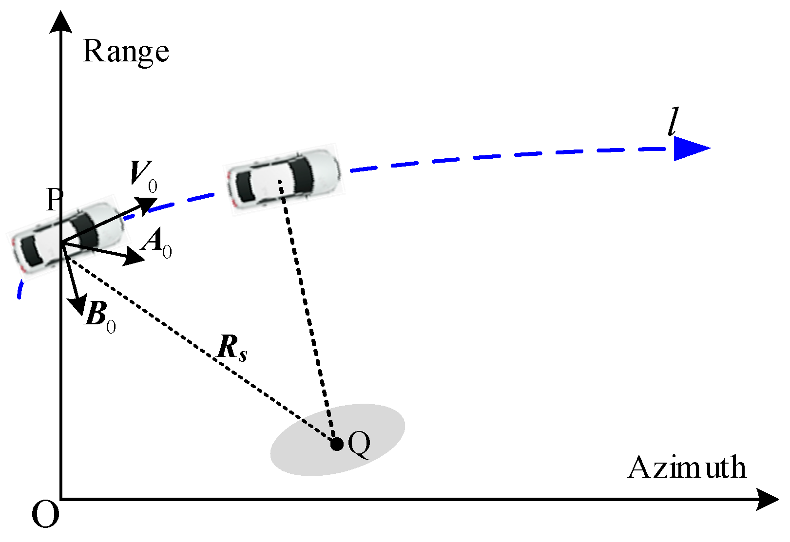
Several studies have investigated ways to improve SAR imaging to make it more suitable for automotive applications. In [22,23,24], near-field (0~100 m) images were obtained using the Range Doppler algorithm (RDA), which validated the feasibility of MMW SARs for vehicle environmental perception under the 77 GHz band. A cooperative SAR (C-SAR) system installed in vehicles has also been employed with broadside images being achieved [25]. The available methods can provide some preliminary demonstrations. However, resolution performance is poor and struggles to meet the operative requirements of automotive applications. To improve the resolution of images, Jiang et al. have presented an improved RDA that divides several range directions, which performs well for the automotive SAR [26]. RDAs are more appropriate for real-time imaging. But their performance is especially poor in cases of curved paths. A range migration algorithm (RMA) employs a wave number domain interpolation without extra approximations, which is more precise and suitable for automotive scenarios [27]. The effectiveness of the RMA is investigated for automotive SARs in [28,29]. In [30], a high-resolution SAR image is obtained using the RMA, which contains vehicles and people in short-range, and satisfies the requirements for automotive applications. The experimental conditions in most available literatures are quite strict, assuming that vehicles maintain a constant velocity linear motion, which deviates from the actual environment. In order to compensate for the motion error, some motion compensation methods have been proposed by [31,32,33,34,35]. In [36], an improved RMA has been proposed for an automotive SAR with a curved trajectory, which is tested using a parking lot experiment. However, the performance would be decreased because of ignoring the space-variance term. Simultaneously, the back-projection algorithm (BPA) is further analyzed by [37], whereby images of curved tracks were able to be obtained. Similar to the RMA, the BPA is also an accurate algorithm without approximate processing [38], and it is suitable for vehicle-mounted near-field scenarios and moving targets focusing [39]. However, the BPA needs to process the signal pulse-by-pulse [40]. As a result, the BPA is not capable of meeting the demands of real-time processing and cannot be applied to engineering applications because of the extensive calculations [41]. Automotive MMW radar systems have a wider antenna beamwidth compared to other platforms. Consequently, the sub-aperture method is also employed to mitigate the beamwidth and maintain the resolution of the imaging results [42,43]. In ref. [44], the system parameters, such as Doppler band and resolution, are analyzed and a sub-aperture PFA is proposed to obtain high-resolution images for curved paths. In terms of computational burden, BPAs and sub-aperture algorithms struggle to meet real-time applications for automotive SARs [45].
In this paper, an extended Omega-K algorithm (EOKA) is proposed to address the challenges associated with automotive SAR imaging. The imaging geometry of a curved path is first constructed, and an equivalent range history equation is derived using the Doppler parameters for automotive SAR. Then, echo data are reconstructed using azimuth resampling to eliminate the non-uniform spatial sampling in EOKA. It makes the range history form similar to the traditional model and facilitates the derivation of the analytical 2D spectrum without using a method of series reversion (MSR). Based on a reconstructed signal model, a new Stolt interpolation is introduced to address the severe range space-variance problem in the automotive SAR imaging scenario. The EOKA is more suitable for curved path automotive SAR in near-field detection.
The structure of this paper is as follows. In Section 2, the geometry model for automotive SAR with a curved path is formulated and an equivalent range model is derived by the Doppler parameters. The echo data is reconstructed using azimuth resampling in Section 3 and an EOKA is proposed. Section 4 presents the simulation and experimental results of automotive SAR in case of curved paths. Finally, the conclusion is drawn in Section 5.

2. Signal Model

The geometric model of the automotive SAR with a curved path is depicted in Figure 1. l is the flight path and point P is the platform position at the aperture center moment (ACM). R s is the slant range vector from point P to an arbitrary point Q at the ACM. V 0 , A 0 and B 0 are respectively the velocity, acceleration and jerk vectors of the platform, which can be extracted from inertial navigation systems (INS) or global position systems (GPS) using the method of polynomial fittings [46].
According to the geometric model, the instantaneous range history R η is given as:
R η = R s + V 0 η + 1 2 A 0 η 2 + 1 6 B 0 η 3
where η is the azimuth slow time and is the absolute value operation. Second-order polynomial fitting is adopted and the fitting results for instantaneous velocity are given in Figure 2. The blue line represents the raw data, and the red dashed line is the fitting result. The phase error caused by instantaneous velocity fitting is given in Figure 3a.
Compared with the hyperbola range model, (1) is precise but complex, which brings challenges 2D spectrum acquisition and focusing approach design. To simplify the complex range model, a new range history equation is derived by the range history relationship with instantaneous Doppler frequency [47]. The expectation range model is expressed as:
R e q η = r s 2 + v e q η + 1 2 a e q η 2 + 1 6 ε η 3 2
where r s = R s , ε is the high-order term, and the v e q and a e q are the equivalent velocity and acceleration, respectively. The equivalent variables can be deduced by the Doppler parameters. The instantaneous Doppler frequency can be given as:
f a η = 2 λ d R e q η d η = 2 λ d R η d η
where λ is the radar wavelength. The expressions of equivalent variables in (2) are obtained by solving numerical equations based on the Taylor series expansion coefficients of the range model in (1) and (2). Then, the equivalent variables in (2) can be calculated using the following:
v e q R s = V 0 2 R s A 0 a e q R s = V 0 A 0 R s B 0 / 3 v e q ε R s = 3 A 0 2 + 4 V 0 B 0 3 a e q 2 4 v e q
where is the inner product operation.
The phase errors of the range model can be derived with the following:
Δ E f = 4 π λ R ^ η R η Δ E e = 4 π λ R ^ η R e q η
where R ^ η is the real range history of the target described by the INS data, Δ E f and Δ E e are phase errors caused by polynomial fitting and equivalent approximation, respectively.
It is known that π / 4 is a threshold value of phase errors. Enormous phase errors have negative effects in imaging results, such as main-lobe widening, side-lobe degradation and geometric distortion. The phase errors resulting from fitting and Equation (2) are displayed in Figure 3. It is noted that both second-order fitting and the equivalent errors are less than π / 4 , which satisfies the requirement, and the equivalent range model is reasonable [46].

3. Imaging Algorithm

Automotive radar environmental perception usually works in the short-range. It results in a range space-variance imaging scene that cannot be ignored. The range space-variance of the equivalent velocity in (4) should especially be considered in the imaging algorithm. Simultaneously, speed changes in the platforms would result in non-uniform spatial sampling. To deal with the above problems, the EOKA is proposed, which is based on the reconstructed range history using azimuth resampling.

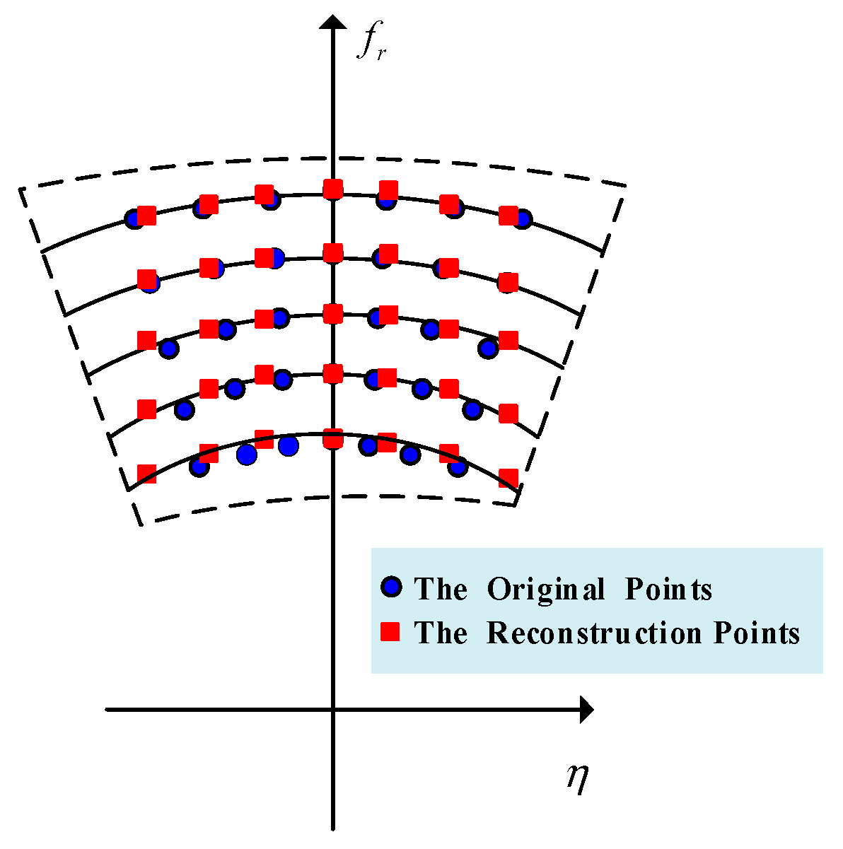
3.1. Range History Reconstruction

After de-chirping, the received signal processed is expressed as follows:
s f r , η = W r f r ω a η exp j 4 π f r + f c c R e q η
where f c is the carrier frequency, c is the light speed and W r and ω a are the window function in range frequency and azimuth time dimension, respectively.
The existence of acceleration a e q and high-order term ε in R e q η would lead to sampling intervals of azimuth time that are non-uniform, which make the traditional algorithm based on uniform sampling disabled.
The azimuth time mapping function is expressed as follows:
η + κ η 2 + χ η 3 η
where η is the new azimuth time, κ = a 0 / 2 v 0 and χ = ε / 6 v 0 are the mapping coefficients and can be calculated using equivalent parameters for the reference point.
After reconstruction, the echo signal becomes:
s f r , η = W r f r ω a η exp j 4 π f r + f c c R e q η
where R e q η is the range history in new azimuth time domain, which is similar to the traditional hyperbola range model.
R e q η = r s 2 + v e q 2 η 2
The essence of range history reconstruction is resampling the echo data. The schematic diagram is demonstrated in Figure 4. The blue dots represent original sampling points and the red squares are the reconstruction ones. Employing the azimuth resampling, the data is rearranged with a similar range history form to the traditional one. Based on the reconstructed range equation, the analytical 2D spectrum would be easily derived by the POSP [15].

3.2. Extended Omega-K Algorithm

Employing Fourier transform (FT) in azimuth direction to (8), the echo signal in 2D wavenumber domain is obtained. The phase can be calculated by POSP as:
φ K r , K a = r s K r 2 K a 2
where K r = 4 π f c + f r / c and K a = 2 π f a / v e q are the range and azimuth wavenumber, respectively.
The bulk compensation function can be constructed by reference range as:
H b u l k K r , K a 0 = exp j r 0 K r 2 K a 0 2
where r 0 is the reference point slant range and K a 0 = 2 π f a / v 0 .
After the bulk compensation, the reference point target could be focused. The residual phase should be compensated to focus the other targets, which can be expressed as follows:
φ r e s K r , K a = Δ r K r 2 K a 0 2 r s K r 2 K a 2 K r 2 K a 0 2
where Δ r = r s r 0 is the range difference between the arbitrary point and the reference point. To remove 2D coupling term, the Stolt interpolation should be applied. The conventional OKAs only deal with the first term in (12) by the Solt mapping function:
K r = K r 2 K a 0 2
where K r is the new range wavenumber.
The second term in (12) introduces the residual phase error, which would generate main lobe widening and side lobe degradation. It would affect the focusing performance. In order to decouple totally, a new Stolt mapping function is derived. The change of equivalent velocity v e q in distance direction can be approximately linear within the mapping belt, which is expressed as:
v e q = v 0 + α Δ r
where α can be obtained by polynomial fitting.
Employing the Taylor series expansion, (12) becomes:
φ ^ r e s K r , K a = Δ r α r 0 4 v 0 2 K a 0 2 K r 2 K a 0 2 + K r 2 K a 0 2
Then, the new Stolt mapping function are adopted to compensate residual range migration, i.e.,
K r = α r 0 4 v 0 2 K a 0 2 K r 2 K a 0 2 + K r 2 K a 0 2
Employing the parameters listed in Table 1, the maximum phase error is 0.05π, which is far less than π/4. This is acceptable for SAR imaging. By the interpolation and mapping, the residual phase is linear with range wavenumber and independent from the azimuth wavenumber. Finally, the phase function is derived as follows:
φ K r , K a = K r Δ r
A focused image is obtained by performing 2D inverse FT (IFT) on (17).
The curved path would cause the range history to be complicated and bring non-uniform spatial sampling in azimuth time, which causes the cross-coupling and spatial variation to deteriorate greatly. The proposed EOKA based on the equivalent range model has a similar process flow to that of the conventional OKA, which is demonstrated in Figure 5. The main distinctions are the range history reconstruction and Stolt interpolation function, which are more suitable for automotive SAR in the case of curved trajectories.

4. Experiment and Discussion

Simulation and experimental results are given to demonstrate the performance of the proposed range model and EOKA. And the image scene is shown in Figure 6, including the simulated scene and the experimental scene.

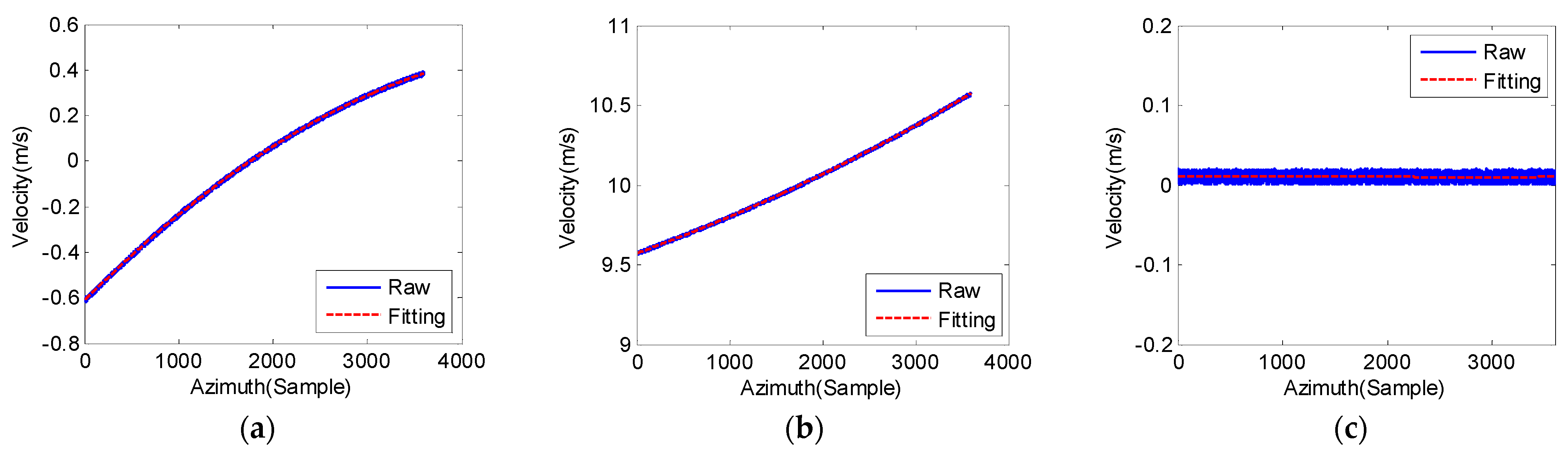
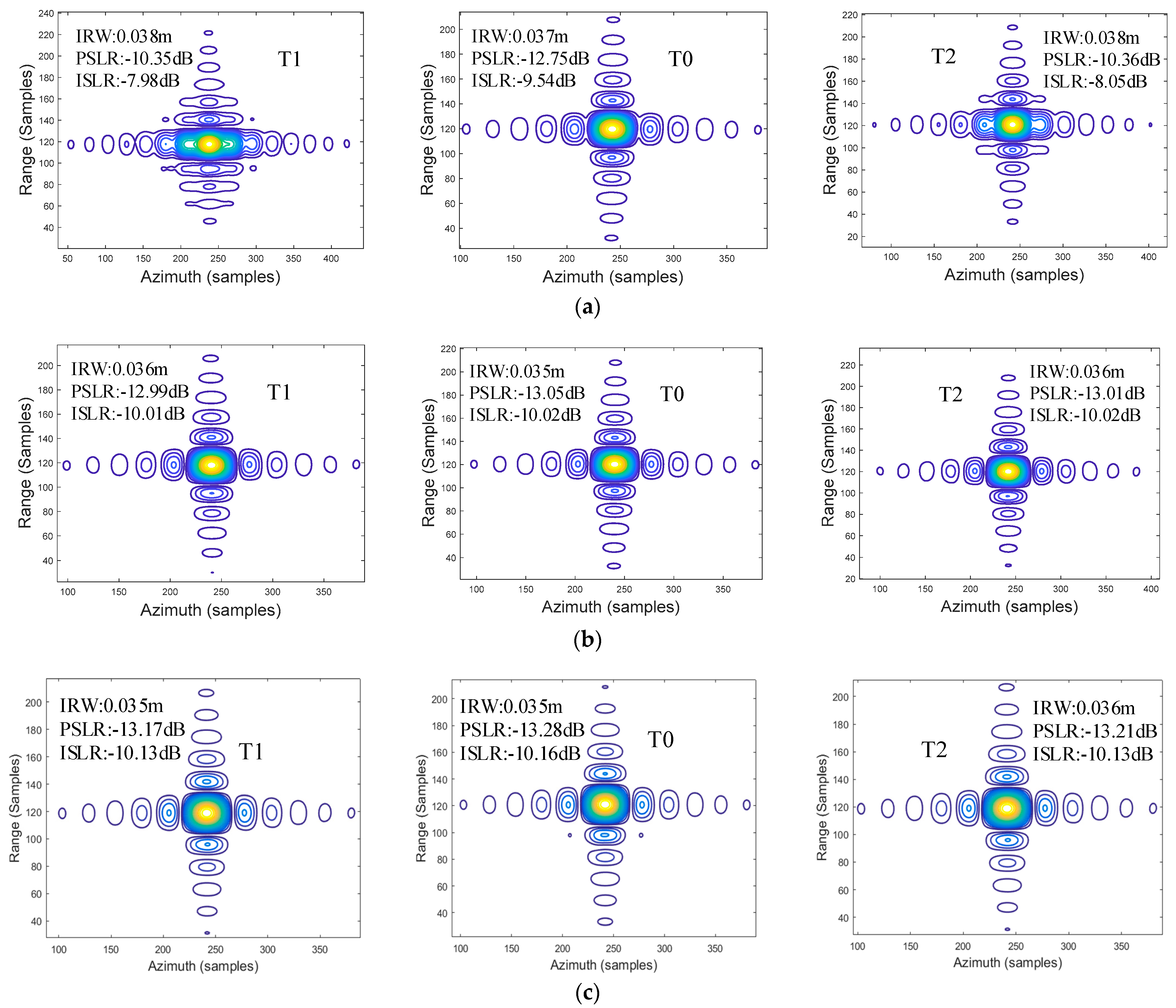
4.1. Simulation Analysis

During the data acquisition process, it was assumed that the vehicle would move along a curved path. Parameters of the radar system are summarized in Table 1. Figure 6a shows the simulated scene and 3 × 3 point targets are arranged on the image scene.
To evaluate the focusing performance of the EOKA, the fast factorized BPA (FFBPA) in [38] and traditional OKA were used for comparison with the proposed method. The impulse response function (IRF) of three targets marked in Figure 6 are given in Figure 7. Figure 7a–c were achieved using the traditional OKA, EOKA and FFBPA, respectively. It was obvious that the targets on the edges could be well focused with the FFBPA and EOKA, whereas the RDA could not because of acceleration and the near field range. Meanwhile, the image quality was evaluated through performance parameters with the azimuth dimension, such as the peak sidelobe ratio (PSLR), integral sidelobe ratio (ISLR) and impulse response width (IRW). Obviously, the performance parameters of the EOKA are closer to the FFBPA, which can be considered as a theoretical value, and can satisfy the requirements of automotive SAR in the curved trajectory scenario.

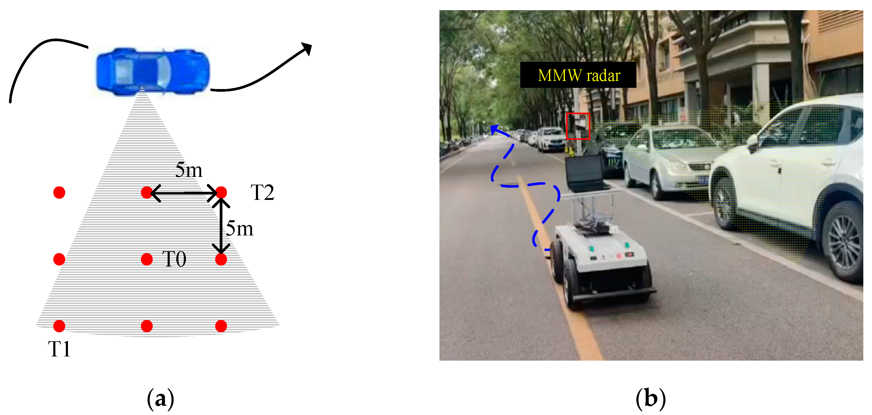
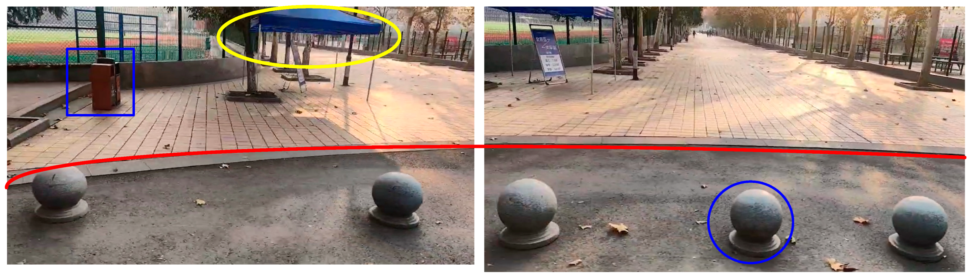
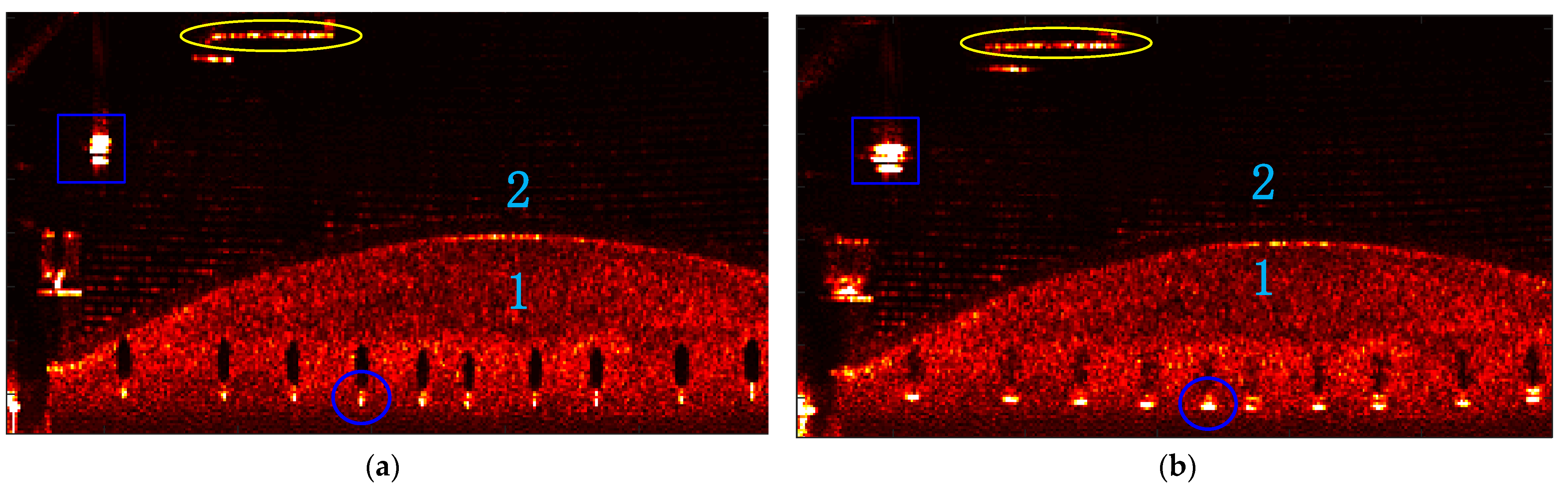
4.2. Real Data Experiments

To verify the effectiveness of the proposed method, real data experiments were performed. The vehicle motion followed the blue curved path as displayed in Figure 6b. The TI AWR1843 MMW radar was adopted to collect the raw data, which worked in strimap mode and was installed in sideway of the vehicle at a height of 1.5 m above the ground. Parameters like carrier frequency and bandwidth were chosen as 77 GHz and 3600 MHz.
The optical image of the obstacle scene is shown in Figure 8. It is stitched together by two optical images. The raw data collection time was 7 s and the velocity of the platform was 4 m/s on average. The acceleration vector extracted from INS was about [0.5, 0.5, 0] m/s2. Figure 9 shows the SAR images focused by the EOKA and OKA. The stone piers which were used to prohibit the vehicles were focused clearly, labeled as area 1 in Figure 9a. The outline of step between area 1 and area 2 is presented clearly in the SAR image, which is marked by red line in the optical image. Meanwhile, the garbage bin, the tent and even the tiles by the road of area 2 are shown, which contribute to obstacle detection. Compared with Figure 9a, the objects, such as garbage bin and stone piers in Figure 9b are obviously defocusing. In addition, to further demonstrate the effectiveness of the proposed method, the image entropy of SAR images processed by different methods are presented. The image entropy of the SAR images obtained by EOKA and OKA were 3.4125 and 3.5383, respectively. It is notable that the proposed algorithm is optimal and can provide high-resolution imaging results, which can offer support for environmental perception when auxiliary parking.
To validate the performance of the proposed method, the focused results of two other scenarios are given in Figure 10. The raw data collection time was 4 s and velocity of platform was 10 m/s on average. The acceleration vector extracted from INS was about [0.5, 1, 0] m/s2. Figure 10a shows the parking lot scene. Vehicles, parking lock, manhole cover and the green belt even the rearview mirror of cars can be well distinguished in the SAR image below Figure 9a. The distance between the two cars is 50 cm, which are framed by the blue rectangle. Another SAR image on an open road is presented in Figure 9b, which can focus the curb, steps, wall and vehicles obviously. The compared targets are circled in optical and SAR images.

4.3. Computational Complexity

The traditional OKA consists of two Fourier Transform (FT) operations in the range dimension, two FT operations in the azimuth dimension, one multiplication operation and one 2D Stolt interpolation operation. In order to simplify the analysis, the size of azimuth is assumed to be same as that of range. The computational complexity of the OKA is as follows:
O O K A = 2 log 2 M + 1 + 2 χ M 2
where M represents the size of data and χ is the length of the interpolation kernel for the Stolt interpolation.
Compared with the OKA, only one azimuth dimension interpolation operation is added in the proposed method. Therefore, the computational complexity of the EOKA is as follows:
O E O K A = 2 log 2 M + 1 + μ + 2 χ M 2
where μ is the length of the interpolation kernel for azimuth resampling.
The computational complexity of FFBPA is can be expressed as follows:
O F F B P A = 4 log 2 M m + 2 m M 2
where m m = 16 denotes the length of sub-aperture under the FFBPA.
All real data were processed using MATLAB R2015b on a computer with an Intel Core i7-13620 CPU and 16.0 GB of RAM. The processing time of the different methods are tabulated in Table 2. It can be seen that the processing time of FFBPA was the longest. The proposed approach is slightly longer than that of the traditional OKA. However, it can obtain high-resolution imaging results similar to that of FFBPA.

5. Conclusions

In this paper, an EOKA has been proposed for automotive SARs in the context of curved paths. An equivalent model is presented to describe the geometry model, which has a similar expression to the conventional model. The echo data was also reconstructed to uniform sampling by azimuth time mapping. And an analytical 2D spectrum is derived without MSR which can be exploited for EOKA. The simulation results and two different experimental scenes, namely a parking lot and an open road scene, demonstrate the performance of the proposed method for automotive SAR. It means that automotive MMW SAR can offer support for environmental perception with high-resolution, which provides technical support for multisensor fusion in intelligent driving.

Author Contributions

P.G.: conceptualization, methodology writing the original paper and supervision; C.L., H.L. and R.W.: modeling and visualization; Y.L. and A.W.: writing-review and editing; S.T.: investigation, writing-review and editing. All authors have read and agreed to the published version of the manuscript.

Funding

This work was supported in part by the National Natural Science Foundation of China under Grants 61701393, and in part by Funded by National Key Laboratory of Science and Technology on Space Microwave, No. HTKJ2022KL504019.

Data Availability Statement

This article is a revised and expanded version of a paper entitled “An improved range migration algorithm based on azimuth time resampling for automotive SAR with curved trajectory”, which was presented at IET International Radar Conference (IRC 2023), Chongqing, China, 2023.

Conflicts of Interest

The authors declare no conflicts of interest.

References

  1. Shopovska, I.; Stojkovic, A.; Aelterman, J.; Hamme, D.V.; Philips, W. High-Dynamic-Range Tone Mapping in Intelligent Automotive Systems. Sensors 2023, 23, 5767. [Google Scholar] [CrossRef] [PubMed]
  2. Patole, S.M.; Torlak, M.; Wang, D.; Ali, M. Automotive radars: A review of signal processing techniques. IEEE Signal Process. Mag. 2017, 34, 22–35. [Google Scholar] [CrossRef]
  3. Engels, F.; Heidenreich, P.; Wintermantel, M.; Stäcker, L. Automotive Radar Signal Processing: Research Directions and Practical Challenges. IEEE J. Sel. Top. Signal Process. 2021, 15, 865–878. [Google Scholar] [CrossRef]
  4. Zhao, Y.; Lei, C.; Shen, Y.; Du, Y.; Chen, Q. Improving Autonomous Vehicle Visual Perception by Fusing Human Gaze and Machine Vision. IEEE Trans. Intell. Transp. Syst. 2023, 24, 12716–12725. [Google Scholar] [CrossRef]
  5. Li, H.; Bamminger, N.; Magosi, Z.F.; Feichtinger, C.; Zhao, Y.; Mihalj, T.; Orucevic, F.; Eichberger, A. The Effect of Rainfall and Illumination on Automotive Sensors Detection Performance. Sustainability 2023, 15, 7260. [Google Scholar] [CrossRef]
  6. Bilik, I.; Longman, O.; Villeval, S.; Tabrikian, J. The Rise of Radar for Autonomous Vehicles: Signal Processing Solutions and Future Research Directions. IEEE Signal Process. Mag. 2019, 36, 20–31. [Google Scholar] [CrossRef]
  7. Bhadoriya, A.S.; Vegamoor, V.; Rathinam, S. Vehicle Detection and Tracking Using Thermal Cameras in Adverse Visibility Conditions. Sensors 2022, 22, 4567. [Google Scholar] [CrossRef]
  8. Sekigawa, Y.; Kidera, S. Doppler Velocity Decomposed Radar Imaging Method for 79 GHz Band Millimeter Wave Radar. In Proceedings of the 2022 International Symposium on Antennas and Propagation (ISAP), Sydney, Australia, 31 October–3 November 2022. [Google Scholar]
  9. Reina, G.; Johnson, D.; Underwood, J. Radar sensing for intel-ligent vehicles in urban environments. Sensors 2015, 15, 14661–14678. [Google Scholar] [CrossRef]
  10. Zhang, W.; Wang, P.; He, N.; He, Z. Super resolution DOA based on relative motion for FMCW automotive radar. IEEE Trans. 2020, 69, 8698–8709. [Google Scholar] [CrossRef]
  11. Iqbal, H.; Löffler, A.; Mejdoub, M.N.; Gruson, F. Realistic SAR implementation for automotive applications. In Proceedings of the 2020 17th European Radar Conference (EuRAD), Utrecht, The Netherlands, 10–15 January 2021. [Google Scholar]
  12. Cui, H.; Wu, J.; Zhang, J.; Chowdhary, G.; Norris, W. 3D Detection and Tracking for On-road Vehicles with a Monovision Camera and Dual Low-cost 4D mmWave Radars. In Proceedings of the 2021 IEEE International Intelligent Transportation Systems Conference (ITSC), Indianapolis, IN, USA, 19–22 September 2021; pp. 2931–2937. [Google Scholar]
  13. Tan, B.; Ma, Z.; Zhu, X.; Li, S.; Zheng, L.; Chen, S.; Huang, L.; Bai, J. 3-D Object Detection for Multiframe 4-D Automotive Millimeter-Wave Radar Point Cloud. IEEE Sens. J. 2023, 23, 11125–11138. [Google Scholar] [CrossRef]
  14. Tan, B.; Zheng, L.; Ma, Z.; Bai, J.; Zhu, X.; Huang, L. Learning-based 4D Millimeter Wave Automotive Radar Sensor Model Simulation for Autonomous Driving Scenarios. In Proceedings of the 2023 7th International Conference on Machine Vision and Information Technology (CMVIT), Xiamen, China, 24–26 March 2023. [Google Scholar]
  15. Sun, S.; Zhang, Y.D. 4D Automotive Radar Sensing for Autonomous Vehicles: A Sparsity-Oriented Approach. IEEE J. Sel. Top. Signal Process. 2021, 15, 879–891. [Google Scholar] [CrossRef]
  16. Maisto, M.A.; Dell’Aversano, A.; Brancaccio, A.; Russo, I.; Solimene, R. A Computationally Light MUSIC Based Algorithm for Automotive RADARs. IEEE Trans. Comput. Imaging 2024, 10, 446–460. [Google Scholar] [CrossRef]
  17. Guo, P.; Wu, F.; Tang, S.; Jiang, C.; Liu, C. Implementation Method of Automotive Video SAR (ViSAR) Based on Sub-Aperture Spectrum Fusion. Remote Sens. 2023, 15, 476. [Google Scholar] [CrossRef]
  18. Laribi, A.; Hahn, M.; Dickmann, J.; Waldschmidt, C. Performance Investigation of Automotive SAR Imaging. In Proceedings of the 2018 IEEE MTT-S International Conference on Microwaves for Intelligent Mobility (ICMIM), Munich, Germany, 15–17 April 2018. [Google Scholar]
  19. Walter, G.; Ron, S.; Ronald, M. Spotlight Synthetic Aperture Radar: Signal Processing Algorithms. J. Atmos. Terr. Phys. 1995, 59, 597–598. [Google Scholar]
  20. Franceschetti, G.; Lanari, R. Synthetic Aperture Radar Processing; CRC Press: Boca Raton, FL, USA, 2018. [Google Scholar]
  21. Han, J.; Tang, S.; Chen, Z.; Ren, Y.; Lian, Z.; Guo, P.; Li, Y.; Zhang, L.; So, H.C. Precise Motion Compensation Approach for High-Resolution Multirotor UAV SAR in the Presence of Multiple Errors. IEEE J. Sel. Top. Appl. Earth Observ. Remote Sens. 2024, 17, 15148–15165. [Google Scholar] [CrossRef]
  22. Tebaldini, S.; Rizzi, M.; Manzoni, M.; Guarnieri, A.; Prati, C.; Tagliaferri, D.; Nicoli, M.; Spagnolini, U.; Russo, I.; Mazzucco, C. SAR imaging in automotive scenarios. In Proceedings of the 2022 Microwave Mediterranean Symposium (MMS), Pizzo Calabro, Italy, 9–13 May 2022. [Google Scholar]
  23. Feger, R.; Haderer, A.; Stelzer, A. Experimental verification of a 77-GHz synthetic aperture radar system for automotive applications. In Proceedings of the 2017 IEEE MTT-S International Conference on Microwaves for Intelligent Mobility (ICMIM), Nagoya, Japan, 19–21 March 2017. [Google Scholar]
  24. Feil, P.; Kraus, T.; Menzel, W. Short Range mm-Wave SAR for Surveillance and Security Applications. In Proceedings of the 8th European Conference on Synthetic Aperture Radar, Aachen, Germany, 7–10 June 2010. [Google Scholar]
  25. Tagliaferri, D.; Rizzi, M.; Tebaldini, S.; Nicoli, M.; Russo, I.; Mazzucco, C.; Monti-Guarnieri, A.; Prati, C.; Spagnolini, U. Cooperative Synthetic Aperture Radar in an Urban Connected Car Scenario. In Proceedings of the 2021 1st IEEE International Online Symposium on Joint Communications & Sensing (JC&S), Dresden, Germany, 23–24 February 2021. [Google Scholar]
  26. Jiang, C.; Tang, S.; Zhang, L.; Sun, J. Real Data Imaging Approach Design for Automotive SAR Experiments. In Proceedings of the 2021 CIE International Conference on Radar (Radar), Haikou, China, 15–19 December 2021. [Google Scholar]
  27. Li, Y.; Zhang, Y.; Liang, J.; Wang, Y. An Improved Omega-K Algorithm for Squinted SAR with Curved Trajectory. IEEE Geosci. Remote Sens. 2024, 21, 4000905. [Google Scholar] [CrossRef]
  28. Zhu, R.; Zhou, J.; Jiang, G.; Fu, Q. Range Migration Algorithm for Near-Field MIMO-SAR Imaging. IEEE Geosci. Remote Sens. 2017, 14, 2280–2284. [Google Scholar] [CrossRef]
  29. Tang, K.; Guo, X.; Liang, X.; Lin, Z. Implementation of Real-time Automotive SAR Imaging. In Proceedings of the IEEE 11th Sensor Array and Multichannel Signal Processing Workshop (SAM), Hangzhou, China, 8–11 June 2020. [Google Scholar]
  30. Zhang, Y.; Zhao, J.; Zhang, B.; Wu, Y. RMA-Based Azimuth-Range Decouple Method for Automotive SAR Sparse Imaging. IEEE Trans. Aerosp. Electron. Syst. 2023, 59, 3480–3492. [Google Scholar] [CrossRef]
  31. Wu, H.; Zwirello, L.; Li, X.; Reichardt, L.; Zwick, T. Motion compensation with one-axis gyroscope and two-axis accelerometer for automotive SAR. In Proceedings of the 2011 German Microwave Conference, Darmstadt, Germany, 14–16 March 2011. [Google Scholar]
  32. Farhadi, M.; Feger, R.; Fink, J.; Wagner, T.; Gonser, M.; Hasch, J.; Stelzer, A. Space-variant Phase Error Estimation and Correction for Automotive SAR. In Proceedings of the 2020 17th European Radar Conference (EuRAD), Utrecht, The Netherlands, 10–15 January 2021. [Google Scholar]
  33. Manzoni, M.; Rizzi, M.; Tebaldini, S.; Monti-Guarnieri, A.; Prati, C.; Tagliaferri, D.; Nicoli, M.; Russo, L.; Mazzucco, C.; Duque, S.; et al. Residual Motion Compensation in Automotive MIMO SAR Imaging. In Proceedings of the 2022 IEEE Radar Conference (RadarConf22), New York, NY, USA, 21–25 March 2022. [Google Scholar]
  34. Wu, X.; Zhu, Z. A novel autofocus algorithm based on minimum entropy criteria for SAR images. Syst. Eng. Electron. 2003, 25, 867–869. [Google Scholar]
  35. Huang, D.; Guo, X.; Zhang, Z.; Yu, W.; Truong, T. Full-Aperture Azimuth Spatial-Variant Autofocus Based on Contrast Maximization for Highly Squinted Synthetic Aperture Radar. IEEE Trans. Geosci. Remote Sens. 2020, 58, 330–347. [Google Scholar] [CrossRef]
  36. Li, H.; Guo, P.; Wang, R.; Zhang, M.; Pan, Z. An improved range migration algorithm based on azimuth time resampling for automotive SAR with curved trajectory. IET Int. Radar Conf. 2024, 2023, 3489–3493. [Google Scholar] [CrossRef]
  37. Oshima, A.; Yamada, H.; Muramatsu, S. Experimental Study on Automotive Millimeter Wave SAR in Curved Tracks. In Proceedings of the International Symposium on Antennas and Propagation (ISAP), Xi’an, China, 27–30 October 2019. [Google Scholar]
  38. Zhang, L.; Li, H.; Qiao, Z.; Xing, M.; Bao, Z. Integrating autofocus techniques with fast factorized back-projection for high resolution spotlight SAR imaging. IEEE Geosci. Remote Sens. Lett. 2013, 10, 104–108. [Google Scholar] [CrossRef]
  39. Farhadi, M.; Feger, R.; Fink, J.; Wagner, T.; Stelzer, A. Synthetic Aperture Radar Imaging of Moving Targets for Automotive Applications. In Proceedings of the 2021 18th European Radar Conference (EuRAD), London, United Kingdom, 5–7 April 2022. [Google Scholar]
  40. Tagliaferri, D. Navigation-aided automotive SAR for high-resolution imaging of driving environments. IEEE Access 2021, 9, 35599–35615. [Google Scholar] [CrossRef]
  41. Liu, Y.; Wang, J.; Bao, Y.; Mao, X. Automotive Millimeter Wave SAR Imaging in Curved Trajectory. In Proceedings of the 2022 14th International Conference on Signal Processing Systems (ICSPS), Jiangsu, China, 18–20 November 2022. [Google Scholar]
  42. Sun, Z.; Jiang, X.; Zhang, H.; Deng, J.; Xiao, Z.; Cheng, C.; Li, X.; Cui, G. Joint Implementation Method for Clutter Suppression and Coherent Maneuvering Target Detection Based on Sub-Aperture Processing with Airborne Bistatic Radar. Remote Sens. 2024, 16, 1379. [Google Scholar] [CrossRef]
  43. Chu, L.; Ma, Y.; Li, B.; Hou, X.; Shi, Y.; Li, W. A Sub-Aperture Overlapping Imaging Method for Circular Synthetic Aperture Radar Carried by a Small Rotor Unmanned Aerial Vehicle. Sensors 2023, 23, 7849. [Google Scholar] [CrossRef] [PubMed]
  44. Liu, Y.; Tao, M.; Shi, T.; Wang, J.; Mao, X. Sub-Aperture Polar Format Algorithm for Curved Trajectory Millimeter Wave Radar Imaging. IEEE Trans. Radar Syst. 2024, 2, 67–83. [Google Scholar] [CrossRef]
  45. Manzoni, M.; Tebaldini, S.; Monti-Guarnieri, A.V.; Prati, C.M.; Russo, I. A comparison of processing schemes for automo-tive MIMO SAR imaging. Remote Sens. 2022, 14, 4696. [Google Scholar] [CrossRef]
  46. Ren, Y.; Tang, S.; Guo, P.; Zhang, L.; So, H.C. 2-D Spatially Variant Motion Error Compensation for High-Resolution Airborne SAR Based on Range-Doppler Expansion Approach. IEEE Trans. Geosci. Remote Sens. 2022, 60, 5201413. [Google Scholar] [CrossRef]
  47. Li, Z.; Liang, Y.; Xing, M.; Huai, Y.; Gao, Y.; Zeng, L.; Bao, Z. An Improved Range Model and Omega-K-Based Imaging Algorithm for High-Squint SAR With Curved Trajectory and Constant Acceleration. IEEE Geosci. Remote Sens. Lett. 2016, 13, 656–660. [Google Scholar] [CrossRef]
Figure 1. Geometry of automotive SAR with curved path.
Remotesensing 16 04508 g001
Figure 2. Real data of INS and fitting results. (a) X, (b) Y and (c) Z.
Remotesensing 16 04508 g002
Figure 3. The phase errors. (a) Fitting, (b) Equation (2).
Remotesensing 16 04508 g003
Figure 4. Range history reconstruction diagram.
Remotesensing 16 04508 g004
Figure 5. Flowchart of the imaging algorithm.
Remotesensing 16 04508 g005
Figure 6. The image scenes. (a) simulated scene; (b) experimental scene.
Remotesensing 16 04508 g006
Figure 7. The IRF of three targets. (a) OKA, (b) EOKA, (c) FFBPA.
Remotesensing 16 04508 g007
Figure 8. The optical image of obstacle scene.
Remotesensing 16 04508 g008
Figure 9. Obstacle focused images. (a) EOKA, (b) OKA.
Remotesensing 16 04508 g009
Figure 10. Focused image. (a) Parking lot scene; (b) Open road scene.
Remotesensing 16 04508 g010
Table 1. Simulated parameters.
ParameterValue
Carrier frequency77 GHz
Bandwidth3000 MHz
Frequency Sweep Period51.2 μs
Reference slant range30 m
Height1.5 m
Velocity vector(12, 0, 0) m/s
Acceleration vector(1, 1, 0) m/s2
Table 2. Processing time.
MethodSceneProcessing Time
Traditional OKAObstacle15 s
Parking lot9 s
Open road8 s
ProposedObstacle20 s
Parking lot11 s
Open road10 s
FFBPAObstacle110 s
Parking lot68 s
Open road55 s
Disclaimer/Publisher’s Note: The statements, opinions and data contained in all publications are solely those of the individual author(s) and contributor(s) and not of MDPI and/or the editor(s). MDPI and/or the editor(s) disclaim responsibility for any injury to people or property resulting from any ideas, methods, instructions or products referred to in the content.

