Abstract
Maintaining the integrity of urban road pavements is vital for public safety, transportation efficiency, and economic stability. However, aging infrastructure and limited budgets make it challenging to detect subsurface defects that can lead to pavement collapses. Traditional inspection methods are often inadequate for identifying such underground anomalies. Ground Penetrating Radar (GPR), especially dual-polarized array systems, offers a non-destructive, high-resolution solution for subsurface inspection. Despite its potential, effectively detecting and analyzing areas at risk of collapse in urban pavements remains a challenge. This study employed a dual-polarized array GPR system to inspect road pavements in London. The research involved comprehensive field testing, including data acquisition, signal processing, calibration, background noise removal, and 3D migration for enhanced imaging. Additionally, Short-Fourier Transform Spectrum (SFTS) analysis was applied to detect moisture-related anomalies. The results show that dual-polarized GPR systems effectively detect subsurface issues like voids, cracks, and moisture-induced weaknesses. The ability to capture data in multiple polarizations improves resolution and depth, enabling the identification of collapse-prone areas, particularly in regions with moisture infiltration. This study demonstrates the practical value of dual-polarized GPR technology in urban pavement inspection, offering a reliable tool for early detection of subsurface defects and contributing to the longevity and safety of road infrastructure.
1. Introduction
In urban infrastructure, maintaining the integrity and safety of road pavements is crucial for ensuring public safety, facilitating transportation, and preserving economic vitality. Road pavements form the backbone of the transportation system of a city, enabling the efficient movement of people and goods and supporting daily economic activities. Safe and reliable pavements reduce travel times, minimize vehicle maintenance costs, and enhance the overall quality of life for residents. Moreover, well-maintained roads are essential for emergency services, ensuring that ambulances, fire trucks, and police can respond quickly to emergencies, thereby saving lives and protecting property. However, the aging infrastructure in many cities presents significant challenges, with deteriorating road pavements arising as a common issue. Many urban areas are faced with road networks that were constructed decades ago and have since experienced extensive wear and tear due to continuous exposure to traffic loading and environmental conditions. Budget constraints often limit the extent and frequency of necessary maintenance and rehabilitation efforts, leading to progressively worsening pavement conditions. Of the various factors contributing to pavement deterioration, one of the most critical is the potential for collapse or subsidence. This can result from various underlying causes, such as soil erosion, underground water movement, and structural weaknesses. Soil erosion—often caused by poor drainage or heavy rainfall—can wash away the supporting soil beneath the pavement, creating voids and weak spots. Underground water movement, including changes in the water table and leaks from pipes, can saturate and weaken subgrade soils. Structural weaknesses, whether from construction defects or material degradation, also compromise pavement integrity. These factors collectively lead to the risk of pavement collapse, posing severe safety hazards and economic impacts [1,2,3].
Traditional methods for inspecting road pavement conditions often rely on visual inspection or manual testing techniques, which may not be sufficiently accurate or comprehensive, particularly for detecting subsurface defects or weaknesses. Ground-penetrating radar (GPR) technology has emerged as a powerful tool for the non-destructive evaluation (NDE) of pavement structures, offering the ability to detect subsurface anomalies with high resolution and accuracy. Early pioneering work has demonstrated the effectiveness of GPR in identifying subsurface voids in asphalt pavements [4,5]. This study involved correlating GPR signal reflections with physical voids confirmed through coring, providing practical validation of GPR’s capability to detect subsurface anomalies that are not visible from the surface. This foundational research highlighted the potential of GPR to enhance pavement maintenance by enabling the early detection of issues that could lead to significant structural failure if left unaddressed. Similar findings were reported by successfully utilizing GPR to detect subsurface voids and anomalies in bridge decks, further underscoring its effectiveness in civil infrastructure evaluation [6,7].
Building on this foundational work, researchers have further explored the use of GPR to detect delamination within pavement layers [8,9]. Delamination (separation between pavement layers) can significantly weaken the structural integrity of roadways and is a critical indicator of potential collapse. This study reported high reliability in identifying these delaminated areas using GPR, showcasing its precision and effectiveness as a diagnostic tool [10]. The ability to non-invasively detect such subsurface defects allows for targeted repairs, thereby extending the lifespan of the pavement and enhancing safety. Another study demonstrated the use of GPR in detecting moisture-related delamination in asphalt pavements, further validating its utility in diverse conditions [11]. Furthermore, research work validates the accuracy of GPR in measuring asphalt layer thickness—another crucial aspect of pavement assessment [12]. Their research showed a strong correlation between GPR measurements and core sample data, confirming the reliability of GPR for this application. The accurate measurement of pavement layer thickness is essential for evaluating the remaining life of a pavement and planning maintenance activities. Similar studies also confirmed the accuracy of GPR in determining pavement layer thickness, thereby supporting its widespread adoption for pavement management [13,14].
Recent advancements in GPR technology have significantly enhanced its capabilities, making it an even more powerful tool for pavement inspection. One of the critical aspects of GPR data acquisition is the polarization of the radar waves, which can significantly influence the quality and interpretability of the subsurface images. Polarization refers to the orientation of the electric field vector of the radar wave. By using multiple polarizations, GPR can capture more detailed and varied information about subsurface features. Each polarization mode interacts differently with subsurface structures, providing unique insights into their properties. Subsurface materials often exhibit anisotropic properties, meaning their physical properties vary with direction. Multiple polarizations can reveal anisotropic features more effectively than a single polarization mode. For instance, horizontal and vertical polarizations might interact differently with elongated structures like pipes or fractures, improving their detectability. Combining data from different polarizations can enhance the resolution of the GPR images. This is particularly useful in complex geological settings where single-polarization data might not be sufficient to resolve intricate details [15,16,17,18]. The integration of HH, VV, HV, and VH modes can produce a more comprehensive subsurface image. Different polarizations interact with subsurface clutter differently. By comparing and combining data from multiple polarizations, it is possible to identify and mitigate clutter, thus improving the signal-to-noise ratio. This is especially beneficial in environments with significant surface clutter or heterogeneous materials. Various polarizations can provide complementary information about the shape, orientation, and material properties of subsurface features. For example, a feature that appears as a strong reflector in HH mode might be less prominent in VV mode, providing clues about its orientation and material composition [19,20,21,22].
One notable development is the advent of dual-polarized array GPR systems. Unlike traditional GPR systems, which transmit and receive signals in a single orientation, dual-polarized systems transmit and receive signals in multiple orientations. This approach provides increased comprehensive subsurface information by capturing data from different polarization angles. Dual-polarized GPR can improve the detection of subsurface anomalies by offering enhanced resolution and depth penetration compared to traditional single-polarized systems [23,24]. This advancement enables more accurate and detailed imaging of subsurface conditions, which is crucial for identifying potential collapse areas. Furthermore, performance has been corroborated in complex subsurface environments using multi-polarization GPR systems [25,26]. Additionally, the introduction of 3D GPR imaging revolutionized subsurface visualization in [27,28]. Traditional 2D GPR provides cross-sectional images of subsurface structures, but 3D GPR imaging can generate detailed volumetric images. The benefits of 3D GPR in providing a more complete and accurate representation of subsurface features are highlighted in [29,30]. This capability facilitates the improved identification and characterization of subsurface anomalies, as it allows for the visualization of complex structures in three dimensions. This advancement is particularly beneficial in urban environments where multiple subsurface utilities and structures can complicate data interpretation. The ability to visualize these features in 3D helps in distinguishing between different types of subsurface anomaly and improving the accuracy of pavement assessments. The effectiveness of 3D GPR in archaeological sites and a demonstration of its broad applicability in detailed subsurface imaging are described in [31,32,33].
Recent advancements in Ground Penetrating Radar (GPR), particularly the development of dual-polarized array systems, have greatly improved pavement inspection capabilities. Unlike traditional GPR, which uses a single polarization, dual-polarized systems transmit and receive signals in both vertical and horizontal orientations. This dual-polarization approach provides a more detailed view of the subsurface, allowing for better discrimination of materials and structures, such as cracks and voids, which reflect signals differently. As a result, the resolution of subsurface imaging is enhanced, enabling more precise detection of potential issues. This increased accuracy is crucial for identifying structural problems early, improving maintenance strategies, and extending pavement life. Additionally, dual-polarized systems offer flexibility in data collection and processing, allowing for customized imaging configurations and improved signal analysis. This helps in distinguishing subtle subsurface anomalies that traditional GPR systems might miss. Overall, dual-polarized GPR systems represent a significant advancement in road inspection technology, leading to more proactive infrastructure maintenance and improved public safety [34,35,36].
This paper presents a comprehensive study on the application of a dual-polarized array Ground Penetrating Radar (GPR) system for inspecting potential collapse areas in city road pavements. To set the context, we begin by reviewing relevant literature on the use of GPR in pavement inspection, highlighting key advancements in the field while addressing the limitations of previous studies. This review helps establish a foundation for understanding the improvements brought by dual-polarized GPR systems. We then describe the survey site and the dual-polarized array system used for data collection, detailing its design and functionality. The core of this paper focuses on the signal-processing strategies employed to detect potential collapse areas. These strategies involve a series of filtering techniques and signal enhancement procedures aimed at refining the data for clearer interpretation. The algorithms we employed include dual-polarization calibration, data pre-processing, data fusion using the polarimetric correlation filter, 3D frequency-wavenumber (f–k) migration, and the short Fourier transform. These algorithms work together to enhance the accuracy and resolution of subsurface imaging, providing more reliable identification of areas at risk of collapse. In Section 3, we present detailed findings on the potential collapse areas identified in this study, supported by data visualizations, such as 3D models, and comparative analysis with prior studies. Finally, we discuss the broader implications of these findings for pavement inspection and urban infrastructure maintenance, emphasizing how the dual-polarized GPR system can be integrated into routine maintenance programs to prevent road collapses and ensure public safety.
2. Materials and Methods
2.1. Aims and Objectives
Building upon the existing literature and advancements in GPR technology, this research aims to investigate the use of a dual-polarized array GPR system for inspecting potential collapse areas in city road pavements. The primary objectives of this study are as follows:
- To assess the effectiveness of dual-polarized array GPR for detecting subsurface anomalies and weaknesses in road pavements.
- To develop and validate a comprehensive methodology for analyzing GPR data and identifying potential collapse areas in road pavements.
- To demonstrate the practical application of dual-polarized array GPR for pavement inspection through field testing and case studies in urban environments.
The scope of the field investigation involves the collection and analysis of GPR data from representative pavement structures. The findings of this study are expected to contribute to the development of advanced techniques for pavement inspection and maintenance, ultimately enhancing the safety and sustainability of urban transportation infrastructure.
2.2. Survey Site and Data Acquisition
The measurement of the potential collapse area was conducted on a segment of city road pavement located in a residential neighborhood in Ealing, London, UK. This investigation specifically focused on a portion of the road measuring approximately 40 m in length and 4 m in width. The selection of this site was based on its critical role in the local traffic network, as it serves both residential traffic and connects to other major roads. The road’s importance, combined with the need for regular maintenance and safety inspections, made it an ideal candidate for this study. Figure 1a presents a broader geographical context of the investigated site via Google Maps 3.58, providing readers with a clear understanding of its location within the residential area. The map also illustrates the surrounding infrastructure, giving insight into the environmental factors that may impact road stability. Figure 1b offers a ground-level view of the exact section under examination, showcasing the designated survey zone. In this image, the area extending from the left side of the road to the roadblock is highlighted, marking the specific stretch of pavement where the measurements were conducted. A red arrow in the figure clearly indicates the survey direction, allowing for easy identification of the exact portion of the pavement being analyzed. This setup ensures that readers can visualize the surveyed area and understand the layout and context of the investigation, which is crucial for interpreting this study’s findings regarding potential collapse risks in this urban setting.
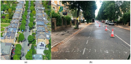
Figure 1.
Investigated potential collapse of city road pavement situated in Ealing, London, UK: (a) Google Map; (b) on-site photograph.
The assessment was specifically designed to detect structural weaknesses or collapse-prone areas within the selected road segment. By identifying these issues early, this study aimed to mitigate potential safety risks before they could develop into more severe problems, thus ensuring the long-term stability and reliability of the road pavement. This proactive approach was critical for maintaining the safety and convenience of Ealing’s residents and daily commuters. Early detection allows for timely intervention, preventing unexpected failures that could lead to accidents, traffic disruptions, or costly repairs. The primary objective was to provide a durable and dependable roadway that would minimize the likelihood of sudden structural issues, ultimately enhancing the overall quality and performance of the infrastructure. By safeguarding this key part of the local traffic network, this study contributes to a safer, more reliable environment for all those who depend on the road for their daily commute and mobility needs.
In order to investigate large-scale 3D GPR measurements, a dual-polarized array GPR system was utilized. This advanced system—identified as the “RIS Hi-BrigHT” GPR system—was manufactured by IDS GeoRadar (Pisa, Italy)—part of Hexagon [37,38]. The system’s sophisticated design is shown in Figure 2a. It features two sets of antennas arranged perpendicularly to each other, known as the HH and VV channels. This configuration allows for the simultaneous acquisition of polarimetric data, significantly enhancing the detail and accuracy of the subsurface images generated. Figure 2b illustrates the antenna configuration, highlighting its complexity and efficiency. The system incorporates 16 transmitting antennas and 16 receiving antennas. This configuration is particularly advantageous because it enables comprehensive data collection across multiple frequencies, which is crucial for creating detailed subsurface images. The system operates at a mid-range frequency of 2.0 GHz, which strikes a balance between penetration depth and resolution. This frequency is optimal for shallow measurements, ensuring that the data collected is both detailed and sufficiently penetrating to effectively reveal subsurface structures.
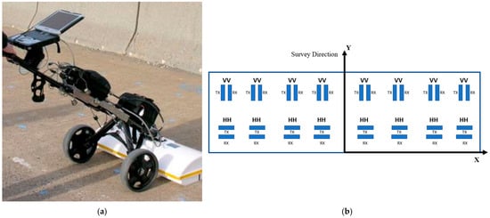
Figure 2.
Dual-polarized array GPR system for investigation of potential collapse areas: (a) RIS Hi-BrigHT GPR system; (b) antenna configuration.
A significant advantage of the “RIS Hi-BrigHT” system over traditional impulse radar is its method of data collection. Each receiving antenna collects data in the frequency domain, allowing more precise and detailed imaging. This method improves the clarity and accuracy of subsurface images, which is critical for various applications, including infrastructure inspection, archaeological investigation, and geological survey. The system is designed to be user-friendly and efficient. Operators can manually pull the system, and data acquisition is triggered at a sampling interval of 2.5 cm, controlled by a distance-measuring wheel. This feature ensures that the data collected are consistent and highly detailed. The system can scan at speeds of up to 7 km/h, making it suitable for rapid surveys over large areas. With each scan covering a width of 0.8 m, the system can quickly gather comprehensive data across extensive survey sites. The remaining parameters of the system are summarized in Table 1.

Table 1.
Dual-polarized array GPR system parameters.
The high-density GPR data acquired by the system facilitate the easy and rapid reconstruction of 3D subsurface images. This capability significantly enhances the efficiency of surveys, facilitating the rapid assessment of large areas. For instance, the investigation of a 40 m by 4 m area can be completed in approximately 15 min, demonstrating the system’s time efficiency and practicality for extensive surveys. The dual-polarized array and the stepped-frequency approach ensure that the GPR data collected are of high quality, enabling detailed and accurate subsurface imaging. This is particularly beneficial for identifying potential structural weaknesses, archaeological artifacts, or geological features. The ease of use, combined with the system’s high efficiency and accuracy, makes the “RIS Hi-BrigHT” GPR system an invaluable tool for professionals in various fields requiring detailed subsurface investigations [39,40]. The whole signal processing flowchart proposed in this paper for pavement inspection is shown in Figure 3, and MATLAB 2023a software was used to gain the processed results in this case study.
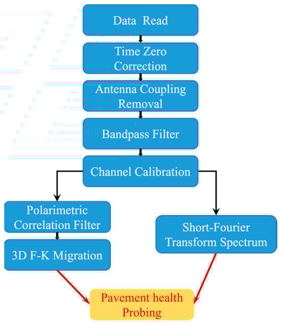
Figure 3.
Flowchart of signal processing with dual-polarized array GPR data.
2.3. Data Processing and Methodology
2.3.1. System Calibration
Since the dual-polarization data will be fused together for further processing, calibration is required to ensure an equalized trace for each channel. This paper details the performance of two crucial calibrations: antenna coupling measurement and ideal target reflection measurement. Firstly, the dual-polarized array GPR system is flipped to face the free space, as illustrated in Figure 4a. In this configuration, the system captures signals containing only the direct coupling from the transmitter antenna to the receiver antenna. Since antenna coupling generally produces the strongest signal among all recorded data, it must be eliminated to ensure precise inspection of shallow subsurface structures. Without this removal, the strong interference from the coupling signal could obscure important details, making it difficult to accurately assess potential structural issues. Secondly, another experiment is conducted where the dual-polarized array GPR system is oriented towards a large metal plate, as depicted in Figure 4b. The metal plate serves as an ideal target, providing uniform phase and amplitude reflections across all channels. This setup facilitates the calibration of both phase and amplitude imbalances across all channels, ensuring that the signals received are consistent in their phase and amplitude. By standardizing the response across all channels, the system ensures that the imaging results are reliable and reflect true subsurface conditions. Without proper calibration, inconsistencies between channels could lead to erroneous interpretations of subsurface features, compromising the effectiveness of the inspection and the overall reliability of the results. By facing the system towards the free space, the direct coupling signal (which would otherwise dominate the shallow reflections) is identified and subsequently removed from the real measurement data. Meanwhile, the metal plate experiment confirms the uniformity of the system’s response, thereby correcting any discrepancies in phase and amplitude among the channels. The reflections from the metal plate of the HH and VV channels are shown in Figure 5. Through these calibrations, the dual-polarized array GPR system is finely tuned, enhancing its capability to deliver precise and reliable subsurface images. This process ensures that the GPR system can accurately detect and characterize subsurface features without the interference of unequal channel responses or dominant coupling signals, leading to more accurate and reliable data interpretation in real-world applications.
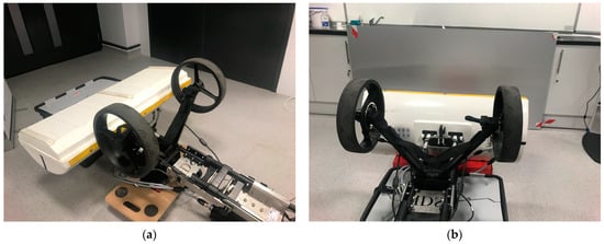
Figure 4.
Dual-polarized array GPR system calibration: (a) antenna direct coupling measurement; (b) phase delay measurement of different channels.
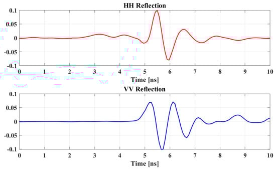
Figure 5.
Metal plate reflections of HH and VV channels.
2.3.2. Data Pre-Processing
- (1)
- Time Zero Correction
Time zero correction is the process of adjusting the start time of the GPR signal to ensure that it accurately represents the point when the radar pulse leaves the antenna and begins to travel through the subsurface. The main goal is to correct any discrepancies caused by system delays or hardware setup so that the time axis of the GPR data correctly align with the true depth or distance. In this paper, we incorporated this procedure by detecting the starting position of the first significant peak and shifting the entire dataset accordingly so that this feature aligned with the zero-time point. This correction ensures accurate depth calculations and improves the clarity of the radargrams.
- (2)
- Background Removal
Background removal is a technique used to eliminate consistent, non-target-related noise or signals from the GPR data. These unwanted signals often originate from system noise, antenna coupling, or other sources that do not change with different scans. The aim is to enhance the visibility of subsurface features by removing repetitive noise patterns that can obscure true reflections from targets of interest. In this paper, we performed the background removal by subtracting an average trace from all the traces in a dataset. This process helps to highlight anomalies and improves the overall signal-to-noise ratio.
- (3)
- Bandpass Filter
Bandpass filtering is a signal processing tool that allows signals within a specific frequency range to pass through while attenuating signals outside this range. The goal is to retain the frequency components of the GPR signal that are most relevant for detecting subsurface features and to suppress frequencies that correspond to noise or irrelevant information. In this paper, bandpass filtering was utilized by selecting a frequency range from 1.2 GHz to 2.8 GHz based on the characteristics of the dual-polarized array GPR system and the expected subsurface conditions. Applying the bandpass filter can enhance the resolution and clarity of the radargrams by reducing the influence of low-frequency noise and high-frequency clutter
2.3.3. Dual-Polarized Data Fusion
After the data pre-processing procedure, we applied the polarization correlation filter (PCF) technique proposed by Zou et al. (2022) for dual-polarization data fusion to enhance the signal-to-noise ratio (SNR) of the reflected signals [41]. The polarization correlation filter is an advanced signal-processing technique used to enhance the detection and characterization of targets by utilizing the polarization characteristics of electromagnetic waves. Polarization refers to the orientation of the electric field vector, which can significantly affect how waves interact with different materials and surfaces. In the dual-polarized systems discussed in this paper, two orthogonal polarization states—horizontal (H) and vertical (V)—are used for transmitting and receiving signals. This dual-polarization approach provides more detailed and diverse data, as it captures how different subsurface materials reflect polarized waves in distinct ways. By analyzing the polarization correlation between the transmitted and received signals, this method improves the clarity and precision of the detected features, making it particularly valuable for applications like subsurface imaging. The ability to distinguish between materials based on their response to polarized waves leads to more accurate interpretations, enhancing the effectiveness of techniques such as Ground Penetrating Radar (GPR). By implementing the PCF, the signal can be significantly enhanced for detection purposes, noise can be reduced, and the accuracy of target identification can be markedly improved. The definition of PCF is as follows:
where indicates the HH GPR profiles and indicates the VV GPR profiles after pre-processing. | | indicates the absolute value. This equation combines the HH and VV signals in both additive and subtractive forms to emphasize the true signal components while mitigating the random noise and systematic interference that might uniquely affect one polarization state or affect them differently. The use of dual polarization inherently reduces noise by cross-referencing the signals from two orthogonal polarizations, which helps in identifying and mitigating noise that appears in only one polarization state. Consequently, the dual-polarization method leads to clearer and more accurate signal detection, classification, and overall data quality. Enhanced signal clarity allows the more precise identification and classification of subsurface targets, which is particularly critical in applications such as archaeological surveys, utility mapping, and geological studies, where precise identification is crucial. Moreover, the dual-polarization approach helps in mitigating different types of interference, whether from environmental sources or the radar system itself, making it a robust solution for various challenging conditions. Figure 6 shows the HH, VV, and PCF filter reflection profiles acquired by the dual-polarized Array GPR system. As shown in this figure, applying the PCF to the pre-processed GPR data resulted in a significant improvement in the SNR. The radargrams produced were markedly clearer, facilitating more precise identification of subsurface structures.
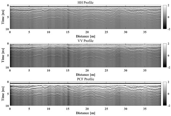
Figure 6.
B-scan reflection profiles acquired by the dual-polarized Array GPR system (HH, VV, and PCF filter).
2.3.4. 3D Migration
In this paper, the 3D frequency-wavenumber (f–k) migration technique is employed to enhance the resolution and accuracy of subsurface imaging. This advanced method transforms raw data from the time–space domain into the frequency-wavenumber domain, allowing for more efficient processing of wave propagation. By processing data in three dimensions, 3D migration can significantly reduce artifacts and noise that often plague 2D GPR images. The algorithm intelligently filters out unwanted signals that may arise from surface clutter or other interference. This leads to cleaner images with better contrast between features of interest and background noise. Three-dimensional migration improves spatial resolution by allowing for finer discretization of the subsurface model. As a result, subtle variations in the subsurface can be detected, leading to more detailed assessments of the ground conditions.
By working within the f–k domain, the technique effectively reconstructs the true positions of subsurface reflectors, improving image clarity and reducing artifacts. The approach addresses the complexities of wave propagation, particularly the challenges in determining the precise locations of features underground. By solving the wave equation governing the propagation of electromagnetic waves, f–k migration offers a more direct and mathematically efficient method than traditional time-domain processing techniques. This makes it particularly valuable for geophysical applications, such as Ground Penetrating Radar (GPR) and seismic imaging, where accurate subsurface mapping is essential for identifying structures or anomalies hidden beneath the surface, leading to a more reliable interpretation of data. The process can be mathematically expressed as follows:
where and denote the 3D Fourier transform and inverse Fourier transform, respectively, represents the GPR data in the time–space domain, is the frequency, is the angular frequency, is the electromagnetic wave propagation velocity through the subsurface, and and are the wavenumbers in the x and y directions, respectively. represents the migrated data in the time–space domain, which provides an enhanced and accurate subsurface image.
The application of 3D f–k migration involves several key steps. Initially, the GPR data, which are collected in the time–space domain, undergo a 3D Fourier transformation to convert them into the frequency-wavenumber domain. This transformation allows for the application of the migration operator, which corrects for the travel time of radar waves and repositions the reflectors to their true spatial locations. The migration operator, represented by the exponential term in the equation, adjusts the phase of each frequency-wavenumber component, effectively focusing the energy at the correct subsurface positions. After applying the migration operator, the data are transformed back into the time–space domain using the inverse 3D Fourier transform. The result is a migrated image that accurately represents subsurface structures, free from distortions caused by the original wave propagation effects. A critical aspect of accurate 3D f–k migration is the availability of a reliable model for the propagation velocity of radar waves through the subsurface materials. This velocity model is crucial because any inaccuracies can lead to errors in the migrated image, such as misplaced reflectors or incorrect depth estimations. For this study, the electromagnetic wave propagation velocity is assumed to be 0.12 m/ns, which is based on the specific pavement materials and conditions encountered. Figure 7 shows the HH, VV, and PCF filtered migrated profiles acquired by the dual-polarized array GPR system. The resulting migrated images are noticeably clearer, aiding in the more accurate identification of subsurface structures, especially in the depth region.
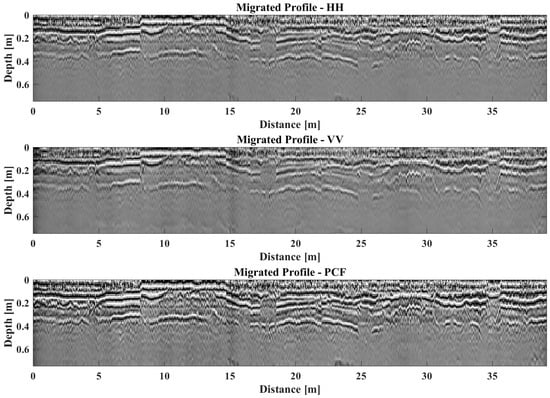
Figure 7.
Migration profiles acquired by the dual-polarized Array GPR system (HH, VV, and PCF filter).
2.3.5. Short-Fourier Transform Spectrum
In this paper, we also applied Short-Fourier Transform Spectrum (SFTS) to analyze the frequency content of a signal over time. The subgrade exhibits pumping phenomena, leading to loosening of the subgrade and resulting in localized areas with higher moisture content than other normal areas. A subgrade with high moisture content will absorb high-frequency radar wave signals, causing the spectral energy peak of the radar reflection to shift towards lower frequencies. SFTS combines aspects of the Fourier Transform and time-domain analysis to provide a time–frequency representation of the signal. Therefore, through SFTS of the GPR reflections, we could find the spectrum shift of this phenomenon and identify the potential collapse area of the pavement. Given a signal x(t), the STFT is defined as follows:
where is the input signal; is the window function; is the time variable, is the angular frequency. is the STFT of .
3. Results
The 3D migration results were obtained by applying the processing procedure discussed in this section. Figure 8 illustrates the migrated vertical profile along the survey direction at 0.1 m in the cross-survey direction. The proximity of this location to the curb results in a thinner top asphalt layer, designed for effective drainage. This design choice ensures that water does not accumulate on the pavement surface, thereby enhancing the longevity of the road. Consequently, the reflection observed at around 8 cm depth marks the boundary between the bottom asphalt layer and the top base layer. This reflection is a critical indicator of the structural integrity and thickness of the asphalt layer, which is essential for maintaining a smooth and durable road surface. Another significant reflection at approximately 30 cm depth delineates the boundary between the bottom base layer and the subgrade. This deeper reflection is crucial as it highlights the transition from the engineered base layer to the natural subgrade, which supports the entire pavement structure. From this figure, we can observe that both boundaries exhibit excellent continuity, indicating a consistent and intact structure. Figure 9 displays the peak frequency division profile obtained through SFTS analysis. In this figure, two continuous frequency peaks are observed around 8 cm and 30 cm depths. The peak frequencies at these depths remain constant, indicating that no damage or water erosion is present in this region. This consistency in the peak frequencies suggests that the structural integrity of the area is maintained, with no signs of deterioration or moisture-related issues. The analysis, therefore, confirms the stability and sound condition of the subsurface at the specified depths. This continuity suggests that the pavement in this section is predominantly in good condition. The clear and continuous reflections of the boundaries demonstrate that there are no significant disruptions or anomalies within these layers, affirming that the layers are well-preserved and without notable defects. These findings are essential for ensuring the road’s long-term performance and guiding maintenance efforts, as they provide a clear picture of the subsurface conditions and highlight any areas that might require attention. Overall, the 3D migration results provide valuable insights into the pavement’s structural health, helping to ensure safe and reliable roadways.
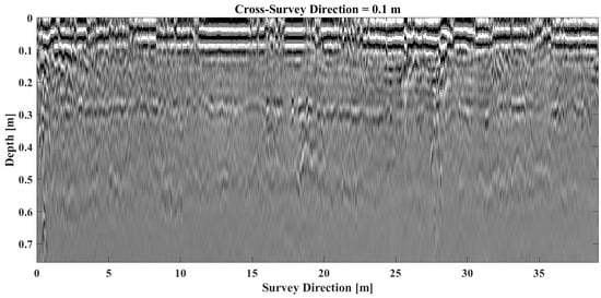
Figure 8.
Migrated profile at 0.1 m; cross-survey direction.
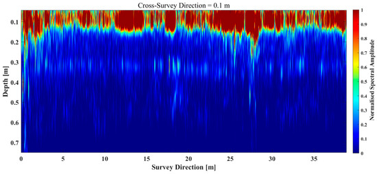
Figure 9.
GPR peak frequency division profile at 0.1 m; cross-survey direction.
Figure 10, Figure 11 and Figure 12 illustrate the migrated vertical profile along the survey direction at 1 m, 2 m, and 2.9 m intervals in the cross-survey direction, respectively. From these figures, the reflection observed at around 14 cm depth marks the boundary between the bottom asphalt layer and the top base layer. Another significant reflection at approximately 30 cm depth delineates the boundary between the bottom base layer and the subgrade. In these figures, we observe discontinuities in different parts of the two boundary regions. Reflected coaxial discontinuities indicate that the subgrade material has been compromised, either due to the pressure exerted by vehicles or the erosive effects of groundwater. Figure 13, Figure 14 and Figure 15 illustrate the peak frequency division profile along the survey direction at 1 m, 2 m, and 2.9 m intervals in the cross-survey direction, respectively. In these figures, we observed a consistent phenomenon across the surveyed region, as also shown in Figure 10, Figure 11 and Figure 12. The low-frequency regions indicate a downward shift in the frequency spectrum due to moisture-related issues. This suggests the presence of moisture within the roadbed material, which compromises its integrity. The crushing of the roadbed material signifies that the road is losing its effective strength and may fail to meet the necessary design requirements. This is particularly concerning in boundary areas showing signs of fragmentation. An increase in the water table in these regions could exacerbate the hollowing out of the road base material, leading to a higher risk of structural collapse. The presence of moisture and subsequent material degradation highlights the urgent need for remediation to prevent further deterioration. These findings underscore the importance of regular monitoring and maintenance to ensure the safety and longevity of the roadway infrastructure, addressing any potential weaknesses before they lead to significant structural failures.
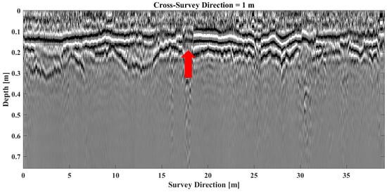
Figure 10.
Migrated profile at 1 m; cross-survey direction.
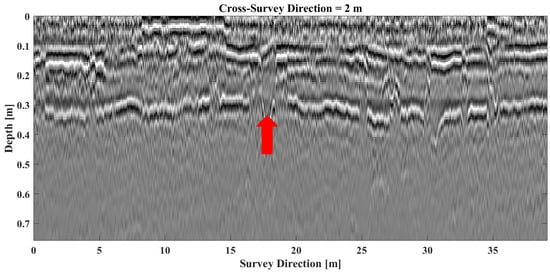
Figure 11.
Migrated profile at 2 m; cross-survey direction.
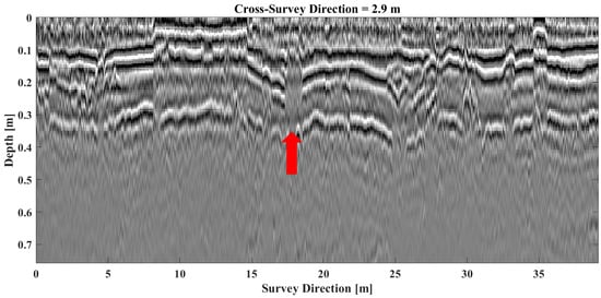
Figure 12.
Migrated profile at 2.9 m; cross-survey direction.
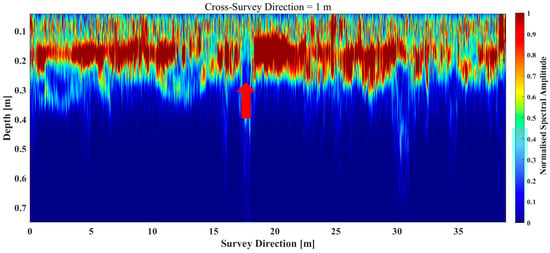
Figure 13.
GPR peak frequency division profile at 1 m; cross-survey direction.
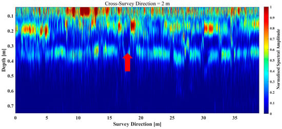
Figure 14.
GPR peak frequency division profile at 2 m; cross-survey direction.
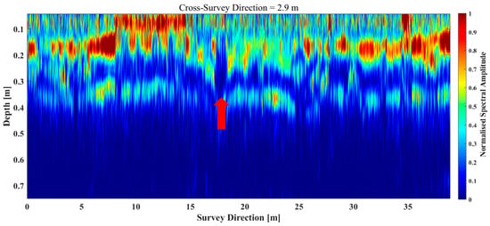
Figure 15.
GPR peak frequency division profile at 2.9 m; cross-survey direction.
In Figure 10, Figure 11 and Figure 12, the regions indicated by red arrows, spanning from 17 m to 18 m in the cross-survey direction, exhibit notable anomalous changes. These anomalies suggest significant disruptions within the subsurface layers, which are likely to be critical weak points. The red arrows shown in Figure 13, Figure 14 and Figure 15 highlight low-frequency regions, further indicating that these areas have high moisture content. This moisture accumulation suggests that these regions are weaker compared to other parts of the pavement. The presence of these discontinuities and anomalies highlights areas where the subgrade has lost its integrity, posing a risk to the overall stability of the road. The observations of fragmentation in both the asphalt and base layers suggest that the structural integrity of the pavement is severely compromised in these regions. This fragmentation not only affects the immediate strength and load-bearing capacity of the pavement but also makes it more susceptible to further damage under adverse weather conditions. For instance, heavy rainfall could infiltrate the compromised subgrade, causing further erosion and weakening the structural support of the pavement. During such extreme weather conditions, the likelihood of collapse increases significantly.
The identified anomalous regions—particularly the area from 17 m to 18 m—warrant immediate attention and intervention to prevent potential failures. Proactive measures, such as reinforcing the affected areas or improving drainage to mitigate groundwater effects, could help in maintaining the structural integrity of the pavement. The implementation of such measures is crucial to prevent the progressive deterioration of the pavement structure, which could lead to more severe failures and higher repair costs in the future. The critical nature of these findings underscores the importance of regular and thorough pavement inspections. Utilizing advanced technologies like GPR for such assessments allows for the early detection of underlying issues that are not visible on the surface. By addressing these issues promptly, the lifespan of the pavement can be significantly extended, ensuring safer and more reliable road conditions for users. Therefore, the anomalies detected in the regions between 17 m and 18 m highlight the urgent need for maintenance and preventive actions. Addressing these weak points through reinforcement and improved drainage will not only enhance the current structural integrity but also mitigate the risks associated with adverse weather conditions, ultimately leading to a safer and more durable road infrastructure.
Figure 16 and Figure 17 present horizontal slices at depths of 0.21 m and 0.36 m, respectively. In these figures, a distinct anomalous region is highlighted within a red ellipse. This region stands out markedly from its surroundings and corresponds with the isophase axis discontinuity observed in Figure 10, Figure 11 and Figure 12. This correspondence validates our earlier assessment that the area between 17 m and 18 m is highly susceptible to collapse. The anomalous characteristics detected at both depths reinforce the notion that this segment of the subsurface is structurally compromised. The consistency of these findings across multiple figures and depths underscores the severity of the issue, indicating that the underlying problems are not isolated to a single layer but rather affect the overall integrity of the subsurface structure in this region. Consequently, this area warrants immediate and focused attention to prevent potential collapse. Monitoring and remediation efforts should be prioritized to address the identified weaknesses, ensuring the safety and stability of the infrastructure. This comprehensive analysis, integrating data from vertical profiles and horizontal slices, provides a robust basis for our conclusion, emphasizing the critical need for proactive measures in this vulnerable zone.
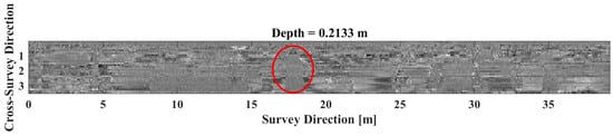
Figure 16.
Migrated horizontal slices at 0.21 m depth.
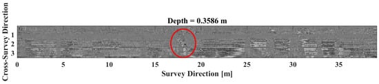
Figure 17.
Migrated horizontal slices at 0.36 m depth.
The detailed analysis provided by the migrated profiles is crucial for identifying and addressing these critical issues. By accurately delineating the boundaries and detecting discontinuities, the 3D migration process enhances our understanding of the subsurface conditions, enabling more informed decision-making for maintenance and repairs. The ability to pinpoint areas at risk of collapse allows for targeted interventions, ensuring that resources are effectively utilized to enhance the durability and safety of the pavement. Overall, the migrated profiles presented in Figure 10, Figure 11 and Figure 12 underscore the importance of continuous monitoring and assessment of pavement structures. The insights gained from these profiles highlight the need for regular inspections and timely maintenance to prevent severe damage and ensure the longevity of the road infrastructure. The observed anomalies serve as a critical reminder of the dynamic nature of subsurface conditions and the necessity of adapting maintenance strategies to address emerging challenges. By doing so, we can safeguard the integrity of the pavement and ensure its functionality for the long term.
4. Discussion
The detection results from the dual-polarized GPR system demonstrate its capacity to accurately identify subsurface anomalies in urban pavement, highlighting its potential as a reliable tool for preemptive infrastructure maintenance. The system effectively detected voids, fractures, and moisture-related weaknesses within the pavement structure, even in complex urban environments. By using dual polarization, the GPR provided distinct horizontal and vertical profiles, each revealing unique structural insights. These multi-dimensional profiles made it possible to distinguish between various types of subsurface anomalies, such as areas with high moisture concentration, which appeared as low-frequency shifts in the radar reflection. This frequency analysis, achieved through SFTS processing, allowed the detection of moisture pockets that weaken subgrade support, increasing the risk of pavement collapse. These findings support the system’s suitability for inspecting urban roadways where a high level of detail is essential for identifying the subtle changes in material properties that precede more significant structural failures.
In addition to moisture-related anomalies, the detection results revealed substantial insights into the physical integrity of the pavement layers, specifically noting the continuity or fragmentation of asphalt and base layers. The dual-polarized GPR system identified distinct boundary reflections at various depths, allowing for a detailed assessment of layer transitions and thickness consistency. For example, reflections at approximately 8 cm and 30 cm depths indicated clear transitions between the asphalt, base, and subgrade layers, affirming the intactness of certain sections. However, in areas where boundary reflections showed discontinuities, the GPR detected weak points likely to be susceptible to subsidence or collapse. These fragmentation points, highlighted by differential reflections in the horizontal and vertical polarization modes, suggest areas where subgrade material is destabilized, potentially due to vehicle load stress or water erosion. The ability to detect these disruptions in pavement continuity early, before visible damage manifests on the surface, highlights the significant contribution of dual-polarized GPR to preventive maintenance efforts by providing actionable data on structural integrity.
The detection results of this study also underline critical risk zones within the surveyed pavement section, particularly regions where the GPR identified notable frequency shifts and phase disruptions, both of which are strong indicators of moisture infiltration and structural degradation. For instance, in the identified risk areas between 17 and 18 m along the survey path, the system recorded low-frequency anomalies and reflection discontinuities, pinpointing sections where the subgrade had likely absorbed moisture or exhibited material loss. The radar profiles able to capture these variances and produce three-dimensional reconstructions of the subsurface enabled an in-depth visualization of weak points, affirming the potential for targeted intervention. These risk zones suggest a need for immediate attention, as the accumulation of moisture within subgrade layers can rapidly exacerbate structural decline, particularly under increased traffic or adverse weather. By identifying these high-risk areas, dual-polarized GPR provides a focused roadmap for maintenance, allowing engineers to address vulnerabilities proactively. Overall, the detection results validate the capacity of the GPR system for detailed, high-resolution imaging, making it an invaluable asset for urban infrastructure management focused on sustainability and safety.
5. Conclusions
This study explores the application of dual-polarized array Ground Penetrating Radar (GPR) for detecting potential collapse areas in urban pavements. The dual-polarized array GPR system, which transmits and receives signals in multiple orientations, provides a comprehensive view of the subsurface and enhances anomaly detection. By capturing data in various polarizations, the system can detect a wider range of subsurface features and inconsistencies that might be missed with traditional single-polarization GPR systems. This broader detection capability is crucial for identifying early signs of structural weaknesses that could lead to collapses.
This study outlines the complete signal processing strategy used in this inspection, including filtering techniques, signal enhancement procedures, and algorithms for identifying potential collapse zones (F–K migration and Short-Fourier Transform Spectrum). The polarization correlation filter technique is essential for removing noise and improving the clarity of the data. Signal enhancement procedures amplify the features of interest, making it easier to detect anomalies. Advanced algorithms then analyze the processed data to pinpoint areas that may be at risk of collapse. Field experiments and results confirm that the proposed strategy effectively identifies potential collapse areas, demonstrating the significant role advanced GPR techniques can play in future pavement inspection and urban infrastructure maintenance. These findings highlight the critical importance of incorporating advanced GPR technology into regular maintenance protocols to ensure the longevity and safety of urban road pavements.
The regular use of such advanced GPR systems can lead to the early detection of problems, allowing for timely repairs and preventing more significant issues. This proactive approach not only improves safety but also extends the lifespan of the infrastructure, reducing long-term maintenance costs. City maintenance programs could incorporate dual-polarized GPR systems for regular inspections of roads, especially in high-traffic areas. By deploying GPR-equipped vehicles at scheduled intervals, maintenance teams can detect early-stage structural damage, such as cracks, voids, or water infiltration, beneath the road surface before they lead to potholes or major damage. Dual-polarized GPR systems could also be used to monitor bridges and overpasses, which are critical infrastructure in cities. Regular GPR scanning would allow for the detection of internal weaknesses, rebar corrosion, or delamination in concrete structures, which could indicate the early stages of structural failure. In regions prone to freezing temperatures, dual-polarized GPR systems could be used to assess the subsurface conditions of roads to detect frost heaving, which occurs when ice forms beneath the surface and displaces the pavement. Early detection of frost heaves allows city maintenance teams to repair the affected areas before they develop into hazardous road conditions like cracks or uneven surfaces. Dual-polarized GPR data could be integrated into a larger predictive maintenance program, where advanced algorithms analyze data over time to predict which sections of a city’s road network are most likely to experience structural failure. This allows cities to proactively address high-risk areas, optimizing repair schedules and reducing the overall cost of road maintenance. Thus, by integrating dual-polarized GPR systems into these regular city maintenance efforts, municipalities can significantly enhance road safety, reduce costly emergency repairs, and extend the lifespan of infrastructure.
Author Contributions
Conceptualization, L.Z. and Y.L.; methodology, L.Z. and Y.L.; software, L.Z.; validation, L.Z., Y.L. and A.M.A.; formal analysis, L.Z. and Y.L.; investigation, L.Z. and Y.L.; resources, L.Z. and Y.L.; data curation, L.Z., Y.L. and A.M.A.; writing—original draft preparation, L.Z.; writing—review and editing, Y.L. and A.M.A.; visualization, L.Z. and Y.L.; supervision, Y.L. and A.M.A.; project administration, A.M.A.; funding acquisition, A.M.A. All authors have read and agreed to the published version of the manuscript.
Funding
This research received no external funding.
Data Availability Statement
The original contributions presented in the study are included in the article, further inquiries can be directed to the corresponding author.
Conflicts of Interest
The authors have no conflicts of interest.
References
- Plati, C. Sustainability Factors in Pavement Materials, Design, and Preservation Strategies: A Literature Review. Constr. Build. Mater. 2019, 211, 539–555. [Google Scholar] [CrossRef]
- Cottrell, W.D.; Bryan, S.; Chilukuri, B.R.; Kalyani, V. Transportation Infrastructure Maintenance Management: Case Study of a Small Urban City. J. Infrastruct. Syst. 2009, 15, 120–132. [Google Scholar] [CrossRef]
- Meneguette, R.I.; De Grande, R.; Loureiro, A.A. Intelligent Transport System in Smart Cities; Springer: Berlin/Heidelberg, Germany, 2018. [Google Scholar]
- Maser, K.R.; Scullion, T. Automated Pavement Subsurface Profiling Using Radar: Case Studies of Four Experimental Field Sites. In Transportation Research Record 1344; Texas Transportation Institute, Texas A&M University: Bryan, TX, USA, 1992. [Google Scholar]
- Peters, L.; Daniels, J.J.; Young, J.D. Ground penetrating radar as a subsurface environmental sensing tool. Proc. IEEE 1994, 82, 1802–1822. [Google Scholar] [CrossRef]
- Slater, L. Near-surface geophysics: A new focus group. EOS Trans. Am. Geophys. Union 2006, 87, 248–249. [Google Scholar] [CrossRef]
- Al-Qadi, I.L.; Leng, Z.; Lahouar, S.; Baek, J. In-Place Hot-Mix Asphalt Density Estimation Using Ground-Penetrating Radar. Transp. Res. Rec. J. Transp. Res. Board 2010, 2152, 19–27. [Google Scholar] [CrossRef]
- Zhen, L.; Al-Qadi, I.L.; Lahouar, S. Development and validation for in situ asphalt mixture density prediction models. NDT E Int. 2011, 44, 369–375. [Google Scholar]
- Plati, C.; Georgouli, K.; Loizos, A. Review of NDT assessment of road pavements using GPR. In Nondestructive Testing of Materials and Structures; Springer: Berlin/Heidelberg, Germany, 2013; pp. 855–860. [Google Scholar]
- Liu, J.; Zollinger, D.G.; Lytton, R.L. Detection of delamination in concrete pavements using ground-coupled ground-penetrating radar technique. Transp. Res. Rec. 2008, 2087, 68–77. [Google Scholar] [CrossRef]
- Solla, M.; Pérez-Gracia, V.; Fontul, S. A Review of GPR Application on Transport Infrastructures: Troubleshooting and Best Practices. Remote Sens. 2021, 13, 672. [Google Scholar] [CrossRef]
- Saarenketo, T.; Scullion, T. Road evaluation with ground penetrating radar. J. Appl. Geophys. 2000, 43, 119–138. [Google Scholar] [CrossRef]
- Loizos, A.; Plati, C. Accuracy of pavement thicknesses estimation using different ground penetrating radar analysis approaches. NDT E Int. 2007, 40, 147–157. [Google Scholar] [CrossRef]
- Dinh, K.; Zayed, T.; Moufti, S.; Shami, A.; Jabri, A.; Abouhamad, M.; Dawood, T. Clustering-Based Threshold Model for Condition Assessment of Concrete Bridge Decks with Ground-Penetrating Radar. Transp. Res. Rec. 2015, 2522, 81–89. [Google Scholar] [CrossRef]
- Liu, H.; Huang, X.; Han, F.; Cui, J.; Spencer, B.F.; Xie, X. Hybrid polarimetric GPR calibration and elongated object orientation estimation. IEEE J. Sel. Top. Appl. Earth Obs. Remote Sens. 2019, 12, 2080–2087. [Google Scholar] [CrossRef]
- Santos, V.R.N.; Teixeira, F.L. Study of time-reversal-based signal processing applied to polarimetric GPR detection of elongated targets. J. Appl. Geophys. 2017, 139, 257–268. [Google Scholar] [CrossRef]
- Sassen, D.S.; Everett, M.E. 3D polarimetric GPR coherency attributes and full-waveform inversion of transmission data for characterizing fractured rock. Geophysics 2009, 74, J23–J34. [Google Scholar] [CrossRef]
- Zhou, H.; Feng, X.; Dong, Z.; Liu, C.; Liang, W. Multiparameter adaptive target classification using full-polarimetric GPR: A novel approach to landmine detection. IEEE J. Sel. Top. Appl. Earth Obs. Remote Sens. 2022, 15, 2592–2606. [Google Scholar] [CrossRef]
- Feng, X.; Yu, Y.; Liu, C.; Fehler, M. Subsurface polarimetric migration imaging for full polarimetric ground-penetrating radar. Geophys. J. Int. 2015, 202, 1324–1338. [Google Scholar] [CrossRef]
- Liu, H.; Zhong, J.; Ding, F.; Meng, X.; Liu, C.; Cui, J. Detection of early-stage rebar corrosion using a polarimetric ground penetrating radar system. Constr. Build. Mater. 2022, 317, 125768. [Google Scholar] [CrossRef]
- Feng, X.; Yu, Y.; Liu, C.; Fehler, M. Combination of H-alpha decomposition and migration for enhancing subsurface target classification of GPR. IEEE Trans. Geosci. Remote Sens. 2015, 53, 4852–4861. [Google Scholar] [CrossRef]
- Zhang, X.; Pei, J.; Sha, X.; Feng, X.; Hu, X.; Chen, C.; Song, Z. Experimental Co-Polarimetric GPR Survey on Artificial Vertical Concrete Cracks by the Improved Time-Varying Centroid Frequency Scheme. Remote Sens. 2024, 16, 2095. [Google Scholar] [CrossRef]
- Lai, W.L.; Dérobert, X.; Annan, P. A review of ground penetrating radar application in civil engineering: A 30-year journey from locating and testing to imaging and diagnosis. NDT E Int. 2017, 96, 58–78. [Google Scholar]
- Dinh, K.; Gucunski, N.; Tran, K.; Novo, A.; Nguyen, T. Full-resolution 3D imaging for concrete structures with dual-polarization GPR. Autom. Constr. 2021, 125, 103652. [Google Scholar] [CrossRef]
- Tsoflias, G.P.; Hoch, A. Investigating multi-polarization GPR wave transmission through thin layers: Implications for vertical fracture characterization. Geophys. Res. Lett. 2006, 33, L20401. [Google Scholar] [CrossRef]
- Zeng, Z.; Li, J.; Huang, L.; Feng, X.; Liu, F. Improving target detection accuracy based on multipolarization MIMO GPR. IEEE Trans. Geosci. Remote Sens. 2014, 53, 15–24. [Google Scholar] [CrossRef]
- Grasmueck, M.; Weger, R.; Horstmeyer, H. Full-resolution 3D GPR imaging for geoscience and archeology. In Proceedings of the Tenth International Conference on Ground Penetrating Radar, 2004. GPR 2004, Delft, The Netherlands, 21–24 June 2004; Volume 1, pp. 329–332. [Google Scholar]
- Novo, A.; Grasmueck, M.; Viggiano, D.A.; Lorenzo, H. 3D GPR in Archeology: What can be gained from dense Data Acquisition and Processing? In Proceedings of the 12th International Conference on Ground Penetrating Radar, Birmingham, UK, 15–19 June 2008; pp. 2–6. [Google Scholar]
- Okazaki, H.; Nakazato, H.; Kwak, Y. Application of high-frequency ground penetrating radar to the reconstruction of 3D sedimentary architecture in a flume model of a fluvial system. Sediment. Geol. 2013, 293, 21–29. [Google Scholar] [CrossRef]
- Grasmueck, M.; Viggiano, D. PondView: Intuitive and Efficient Visualization of 3D GPR Data. In Proceedings of the 2018 17th International Conference on Ground Penetrating Radar (GPR), Rapperswil, Switzerland, 18–21 June 2018; pp. 1–6. [Google Scholar]
- Böninger, U.; Tronicke, J. Integrated data analysis at an archaeological site: A case study using 3D GPR, magnetic, and high-resolution topographic data. Geophysics 2010, 75, B169–B176. [Google Scholar] [CrossRef]
- Zhao, W.-K.; Tian, G.; Wang, B.-B.; Shi, Z.-J.; Lin, J.-X. Application of 3D GPR attribute technology in archaeological investigations. Appl. Geophys. 2012, 9, 261–269. [Google Scholar] [CrossRef]
- Leucci, G.; De Giorgi, L.; Di Giacomo, G.; DiTaranto, I.; Miccoli, I.; Scardozzi, G. 3D GPR survey for the archaeological characterization of the ancient Messapian necropolis in Lecce, South Italy. J. Archaeol. Sci. Rep. 2016, 7, 290–302. [Google Scholar] [CrossRef]
- Pasculli, D.; Giannino, F.; Simi, A.; Manacorda, G. High-density dual polarized GPR array for underground asset mapping. In Proceedings of the 2017 9th International Workshop on Advanced Ground Penetrating Radar (IWAGPR), Edinburgh, UK, 28–30 June 2017. [Google Scholar]
- Zou, L.; Liu, H.; Alani, A.M.; Fang, G. Surface Permittivity Estimation of Southern Utopia Planitia by High Frequency RoPeR in Tianwen-1 Mars Exploration. IEEE Trans. Geosci. Remote Sens. 2024, 62, 2002809. [Google Scholar] [CrossRef]
- Sun, H.H.; Cheng, W.; Fan, Z. Diameter estimation of cylindrical metal bar using wideband dual-polarized ground-penetrating radar. IEEE Trans. Instrum. Meas. 2023, 72, 8000714. [Google Scholar] [CrossRef]
- Alani, A.M.; Aboutalebi, M.; Kilic, G. Applications of ground penetrating radar (GPR) in bridge deck monitoring and assessment. J. Appl. Geophys. 2013, 97, 45–54. [Google Scholar] [CrossRef]
- Novo, A.; Manacorda, G.; Simi, A. Multichannel 3D GPR array systems: Recent results in engineering and archaeology. In Proceedings of the 26th Symposium on the Application of Geophysics to Engineering and Environmental Problems, Denver, CO, USA, 17–21 March 2013; pp. 433–441. [Google Scholar]
- Kaur, P.; Dana, K.J.; Romero, F.A.; Gucunski, N. Automated GPR Rebar Analysis for Robotic Bridge Deck Evaluation. IEEE Trans. Cybern. 2015, 46, 2265–2276. [Google Scholar] [CrossRef] [PubMed]
- Stryk, J.; Alani, A.M.; Matula, R.; Pospisil, K. Innovative Inspection Procedures for Effective GPR Surveying of Critical Transport Infrastructures (Pavements, Bridges and Tunnels). In Civil Engineering Applications of Ground Penetrating Radar; Springer Transactions in Civil and Environmental Engineering: Berlin/Heidelberg, Germany, 2015. [Google Scholar]
- Zou, L.; Tosti, F.; Alani, A.M. Nondestructive inspection of tree trunks using a dual-polarized ground-penetrating radar system. IEEE Trans. Geosci. Remote Sens. 2022, 60, 5917108. [Google Scholar] [CrossRef]
Disclaimer/Publisher’s Note: The statements, opinions and data contained in all publications are solely those of the individual author(s) and contributor(s) and not of MDPI and/or the editor(s). MDPI and/or the editor(s) disclaim responsibility for any injury to people or property resulting from any ideas, methods, instructions or products referred to in the content. |
© 2024 by the authors. Licensee MDPI, Basel, Switzerland. This article is an open access article distributed under the terms and conditions of the Creative Commons Attribution (CC BY) license (https://creativecommons.org/licenses/by/4.0/).