Article

Error Analysis of Non-Time-Synchronized Lightning Positioning Method

1
School of Emergency Management, Institute of Public Security Governance, Nanjing University of Information Science and Technology, Nanjing 210044, China
2
Guizhou Power Grid Duyun Power Supply Bureau, Duyun 558000, China
3
Public Technical Service Center, Pingliang Land Surface Process & Severe Weather Research Station, Northwest Institute of Eco-Environmental Resources, Chinese Academy of Sciences, Lanzhou 730000, China
*
Author to whom correspondence should be addressed.
Remote Sens. 2024, 16(18), 3443; https://doi.org/10.3390/rs16183443
Submission received: 22 July 2024 / Revised: 28 August 2024 / Accepted: 7 September 2024 / Published: 17 September 2024

Abstract

:
Since the non-time-synchronized lightning positioning method does not rely on the time synchronization of the stations in the positioning system, it eliminates the errors arising from the pursuit of time synchronization and potentially achieves higher positioning accuracy. This paper provides a comprehensive overview of the errors present in the three-dimensional lightning positioning system. It compares the results of traditional positioning methods with those of non-time-synchronized lightning positioning algorithms. Subsequently, a simulation analysis of the positioning errors is conducted specifically for the non-time-synchronized lightning positioning method. The results show that (1) the non-time-synchronized lightning positioning method exhibits greater errors when utilizing two randomly positioned radiation sources for location determination. Consequently, the resulting positioning outcomes only provide a general overview of the lightning discharge. (2) The positioning outcomes resemble those of the traditional method when employing a fixed-coordinate beacon point. However, the errors in the three-dimensional positional coordinates of these fixed-coordinate beacon points significantly impact the deviations in the positioning results. This impact is positively correlated with the positional error of the beacon point, considering both the orientation and magnitude. (3) Similarly to the traditional method, the farther away from the center of the positioning network, the larger the radial error. (4) The spatial position of the selected fixed-coordinate beacon point has little influence on the error.

1. Introduction

Currently, lightning positioning systems based on the time difference principle are becoming more and more widely used [1,2,3,4,5,6,7,8,9,10,11,12,13,14,15,16]. These positioning systems rely on time synchronization for lightning positioning. The positioning accuracy of the existing time-differential positioning systems relies heavily on multi-station clock synchronization technology; for example, the presence of timing errors in high-precision GPS clocks causes the total error to have a certain basic error value [1,5,10]. In addition, some specific conditions, such as the aging or damage of the GPS antenna or a lack of satellite signals, can cause the disablement of some stations in the time-differential positioning system or even the whole positioning network. Even if we use other satellite systems or atomic clocks to achieve synchronization, we still cannot completely avoid the synchronization errors that occur due to the pursuit of synchronization. Our proposed non-time-synchronized lightning positioning method does not rely on time synchronization and thus does not need the timing information of a GPS high-precision clock [17]. Moreover, the system is simplified due to the absence of the GPS system, which improves the stability and robustness of the operation of the time-differential positioning system. To better understand the error issues of non-time-synchronous positioning methods, a comprehensive overview of the possible errors of the lightning positioning system is presented in this paper. The incremental refinement and preliminary effectiveness testing of the non-time-synchronized lightning positioning method are carried out by comparing the positioning results of the traditional positioning method with the positioning of an individual lightning case. Further, the non-time-synchronized three-dimensional (3D) lightning positioning method is simulated and analyzed in terms of its positioning errors.
Regarding the error analysis of the lightning positioning system, it can be carried out by comparing the trajectory positioning of balloon-borne signal sources [6,18] or simply using the experimental data of artificial lightning instances to roughly determine the error of the system [15]. A more comprehensive error analysis needs to be performed through simulation. This could involve using Monte Carlo methods to simulate the error distribution of the lightning positioning system [10,17,19]. Given that the Monte Carlo method fails to distinctly represent the direction of radial errors, as well as horizontal longitudinal and transverse errors, this study, building on the error analysis conducted by Wang et al. [17], adopts an alternative approach to the Monte Carlo error distribution. It utilizes circular and square plots for error analysis, aiming to intuitively illustrate the disparity between the radial and horizontal error distributions in this positioning method. Due to the utilization of two radiation sources’ arrival time intervals for joint positioning [17], involving the challenge of spatial location errors in two radiation sources acting as a beacon point, the primary focus of this work is to simulate the effects of a non-fixed beacon point and a fixed beacon point with errors and the spatial locations of the beacon points on the overall positioning results’ error distribution. Additionally, the analysis includes examining the impact of different distances between two simultaneously localized radiation sources on the positioning results. This work can provide a reference for the further development and application of the non-time-synchronized lightning method.

2. The Principle of the Non-Time-Synchronized Lightning Positioning Method

The schematic diagram of the non-time-synchronized lightning positioning method is depicted in Figure 1. In this illustration, two discharging radiation sources occur in space, emitting electromagnetic pulse signals. On the ground, seven signal-receiving base stations are established. Due to the varying distances from each radiation source to the seven stations, the propagation times of the electromagnetic signals differ as they travel from the radiation source locations to the seven receiving base stations.
In the continuously recorded waveform of the lightning electromagnetic signal, we can measure the time interval between any two pulses in a segment of the waveform, given the specified data sampling rate. Pulse matching among the seven stations can be accomplished using either the generalized cross-correlation method [7] or the EMD–Pearson method [16]. These methods involve initially matching the entirety of the waveform segments of the seven stations and then performing pulse matching to obtain arbitrary two-pulse intervals for different stations.
Assume that the time of occurrence of radiation source “a” is ta, and the position relative to the main station is (xa, ya, za); the time of occurrence of radiation source “b” is tb, and the position relative to the main station is (xb, yb, zb); and the position of station “i” is (xi, yi, zi), and the time of receiving the pulse from radiation source “a” is tia.
Next, assume that the lightning radiation source “a” occurs at time ta, and its position relative to the center of the positioning network is (xa, ya, za); the lightning radiation source “b” occurs at time tb, and its position relative to the center of the positioning network is (xb, yb, zb); and the position of the station “i” is (xi, yi, zi) and the time at which the “a” pulse from the radiation source “a” reaches the station “i” is tia. Here, station “i” denotes the base station labeled “i”, and “ϲ” is the propagation speed of an electromagnetic wave in the air.
The mathematical expression for the non-time-synchronized lightning positioning method is represented by Equation (1), denoting the equation obtained for station “i”. The seven stations yield a system of equations containing seven individual equations, thereby enabling the computation of seven unknown variables: ΔT, xa, ya, za, xb, yb, zb.
t i = t   +   1 c ( ( x b x i ) 2 + ( y b y i ) 2 + ( z b z i ) 2 ( x a x i ) 2 + ( y a y i ) 2 + ( z a z i ) 2 )
where Δti = tib − tia denotes the double-pulse interval between pulse “a” and pulse “b” in the waveform in station “i”. Δt = tb − ta denotes the double-pulse interval between the occurrence time ta of radiation source “a” and the occurrence time tb of radiation source “b”. The detailed derivation procedure of the non-time-synchronized lightning positioning method is provided in the literature [17].
By substituting the double-pulse intervals (∆t1 to ∆t7) of the seven base stations into the system of Equation (1), it becomes possible to calculate the three-dimensional spatial positions of the lightning radiation sources “a” and “b”, along with the time intervals between the occurrences of the two sources. Consequently, the specific time of occurrence of the radiation sources can be deduced based on the standard time of the central station.

3. Introduction to Positioning System Errors

In the traditional time-differential positioning system [7,20,21], errors arise from various sources, including the timing errors of the GPS clock, distortions caused by digitized sampling, tropospheric delay errors of electromagnetic waves, cumulative errors of the crystal frequency in the acquisition system [22], and the positional errors of each probe station. The non-time-synchronized lightning positioning method also encompasses several error types, except for GPS clock errors.

3.1. Extraction Errors of Lightning Pulse Signals

During the discharge process, lightning discharges emit strong electromagnetic waves covering a broad spectrum of frequency bands, ranging from a very low frequency (VLF) to a very high frequency (VHF). As an illustrative example, we consider the lightning VHF radiation source 3D positioning system established in Qinghai Province in China, situated at the northeastern foothills of the Qinghai–Tibetan Plateau [5]. The VHF antenna receiving system at the station features a center frequency of 270 MHz, a bandwidth of 6 MHz, and a broadband system with bandwidths ranging from 160 Hz to 10 MHz. The station is equipped with a 40 MHz high-precision clock and a GPS receiver.
After the lightning radiation source reaches the station, it undergoes processing through a band-pass filter and an amplifier. The 40 MHz reference signal, output by bisection, serves as the sampling clock for the A/D converter. In Figure 1, a lightning detection network comprising seven stations is defined on the ground. Utilizing the aforementioned VHF antenna receiving system, electromagnetic pulse signals from radiation sources “a” and “b” are received. Disregarding the GPS positioning error of the detection stations and the tropospheric delay error, the seven stations individually extract electromagnetic signals from sources “a” and “b”, as depicted in Figure 2. A 20 MHz acquisition card, i.e., sampling 2 × 10⁷ times per second, is employed, with the sampling clock for the A/D converter set at 2 × 10⁷ times and a sampling period of 50 ns.
Figure 2 below illustrates the acquisition process of the seven stations receiving electromagnetic signals from two sources. The blue and green points represent the arrival moments of the radiation pulses from sources “a” and “b”, respectively. We denote the arrival moment of the ith station receiving radiation source “a” as tai and the arrival moment of radiation source “b” as tbi. The station records the actual arrival moments of the signals from sources “a” and “b” as tai′ and tbi′, respectively, with a sampling period of tp (50 ns). The closer the signals arrive at the station to the center of the sampling period, the smaller the error will be. Therefore, we can express this relationship as
t 1 = t b 1 t a 1 = ( t b 1 + n t p ) ( t a 1 + m t p ) ( 1 2 n , m 1 2 )
From Equation (2), we can infer that when the values of “n” and “m” are both 0, it represents the ideal state, and the extraction error is 0. However, in practical applications, the extraction error interval is between −50 ns and +50 ns. This signifies that the error range for the extraction of lightning signals using a 20 MHz acquisition card is ±50 ns. Therefore, under the condition that the signal frequency band meets the requirements, opting for an acquisition card with a higher acquisition frequency can effectively minimize the extraction error (i.e., digitization error) of the lightning signal, consequently enhancing the positioning accuracy.

3.2. Tropospheric Delay Errors

In the process of electromagnetic signals travelling through the Earth’s atmosphere to the receiver, atmospheric refraction changes both the speed and direction of signal propagation, resulting in a delayed effect. The neutral atmosphere (approximately below 50 km) is divided into the troposphere and stratosphere. The troposphere consists of more than 80% of the atmospheric mass and almost all of the water vapor, and the density of the gas and water vapor directly determines the degree of signal delay. Thus, the delay of electromagnetic wave signals in the neutral atmosphere is collectively referred to as the tropospheric delay [23]. Tropospheric delay is one of the main sources of error in radio navigation positioning, and the size of the tropospheric delay is about 2 m in the zenith direction, while its effect can be more than 20 m near the ground [24]. This is related to the fact that satellite signals need to traverse distances of more than 50 km. The propagation of lightning electromagnetic waves in the atmosphere will be affected accordingly. For the simulation area in this study with a network radius of 10 km, the tropospheric delay of the electromagnetic wave between the stations is about 1 m or less, and the time delay error can be loosely controlled to be less than 5 ns, so the tropospheric delay error can be considered negligible in this case.

3.3. Position Error of the Lightning Detection Station Itself

At present, the mainstream positioning systems mainly include GPS, BeiDou, and Galileo satellite navigation systems, etc. These positioning systems exhibit errors in practical applications, and the size of the error is not the same. In this study, we mainly consider the use of GPS for the accurate positioning of the spatial three-dimensional position of the lightning detection station; the GPS receiver in the system used to acquire the data in this work has a horizontal position error of 3–5 m and an elevation error of about 10–20 m. According to Equation (1), we know that, when solving for the location of the radiation source, the position error of the detection station will lead to a change in xi, yi, zi and then affect the accuracy of positioning.

4. Lightning Positioning Results Based on Non-Time-Synchronized Positioning Method

To further validate the feasibility of the non-time-synchronized positioning method, we employ this approach to reposition the measured broadband electric field data from the Lightning Mapping System (LMS) [5]. Subsequently, we compare these results with the positioning outcomes obtained using the traditional method. Notably, the non-time-synchronized method exclusively utilizes the electric field waveform data and does not require the corresponding timing information from the GPS high-precision clock, as required by the traditional method.
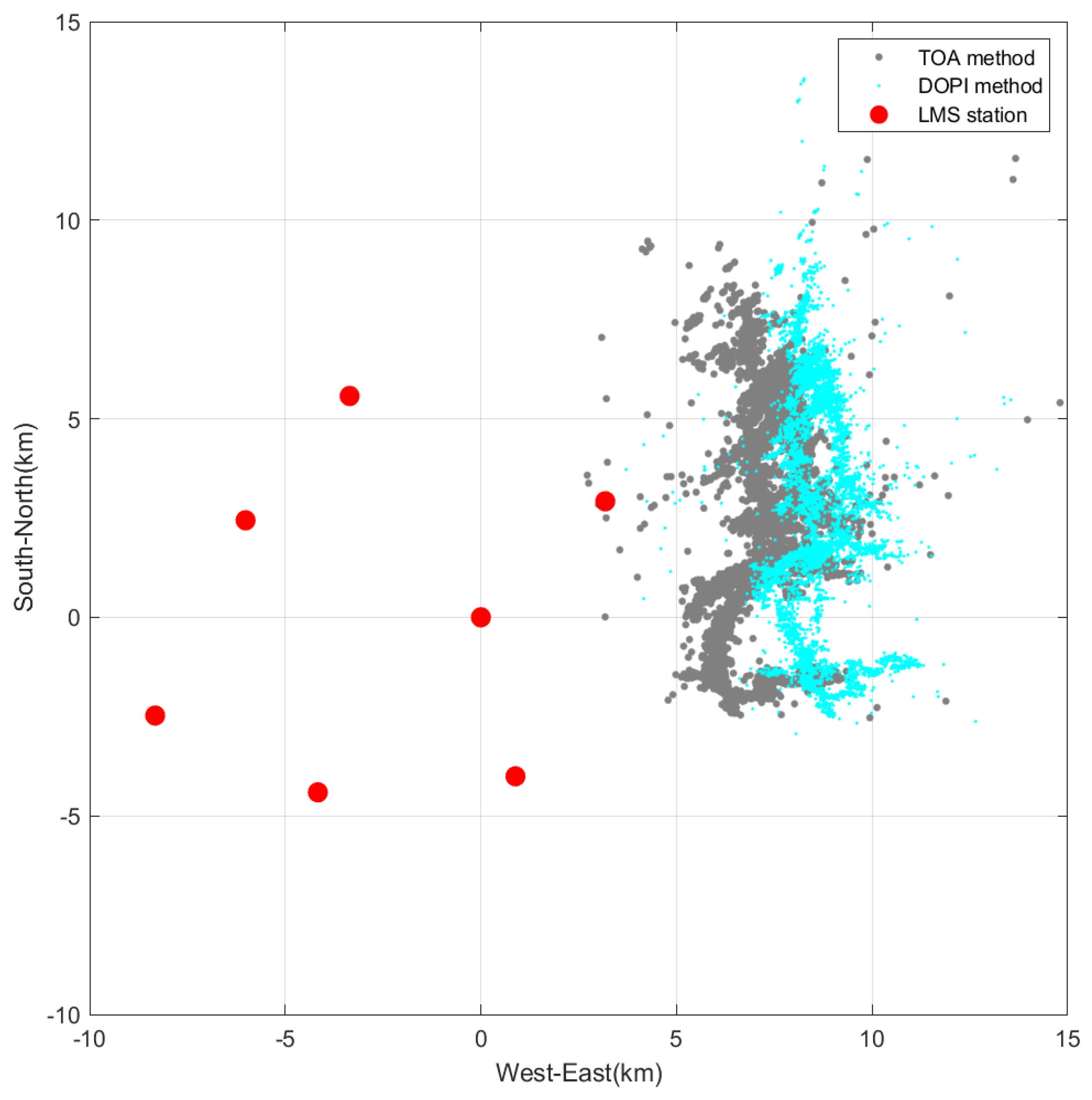
In Figure 3, the grey positioning results are those of the LMS, and the cyan positioning results are those of the repositioning using the non-time-synchronized method. As shown in the legends of Figure 3, Figure 4 and Figure 5, TOA denotes the “time difference of arrival” and DOPI denotes the “difference of pulse interval”. It can be found that the positioning results obtained using the non-time-synchronized method are in the same area as the results of the LMS, and the shape of the lightning can also be roughly seen. Since the data sampling rate of the measured data is 20 M/s, there exists a pulse interval extraction error within the interval of ±50 ns. This error fluctuates up and down with the selection of different positioning points. Under this pulse interval error, the lightning channel positioning results of the non-time-synchronized method are relatively scattered. Compared with the positioning results of the LMS, the non-time-synchronized positioning method has a large positioning error.
Considering that the non-time-synchronized lightning positioning method is the result of joint positioning using two radiation sources, the randomness associated with the simultaneous positioning of two radiation sources may affect the accuracy of the positioning. Therefore, when we calculate the same real lightning instance, we first calculate all pairs of rough positioning points using the non-time-synchronized algorithm and mark one of the calculated positions as a beacon point. In addition, the 3D position coordinates of this positioning of the beacon point are used as known parameters to be substituted into Equation (1) to localize the rest of the radiation sources of the lightning, and the positioning results are shown in Figure 4. In comparison with the positioning results shown in Figure 3, it can be seen that the structure of the lightning channel is convergent and is also consistent with the results localized by time-differential positioning systems. Moreover, it bears a resemblance to the lightning discharge channel observed in the positioning results of the time-difference positioning method. Hence, we posit that selecting the single positioning value of the beacon point as a known parameter and substituting it into the joint positioning process can enhance the accuracy of the positioning results. Simultaneously, we observe that when employing joint beacon point positioning, there is a dispersed eastward offset in the overall lightning image in the non-time-synchronized positioning. This discrepancy may be attributed to the presence of a positional error in the beacon point, a factor that will be simulated and analyzed in the subsequent section.
Considering that the positional error of the beacon point may impact the positioning results, in order to obtain the more accurate positioning of the co-located points, we select a fixed co-located point, calculate it with all other radiation source pulses, and then obtain the average of the results of the position calculations of all co-located points. Based on Figure 4, this average value is then used as the fixed-coordinate beacon point. Through iterative calculations, we conduct joint positioning. The obtained positioning results are presented in Figure 5, where it is evident that the results align well with the original lightning channel positioning outcomes; moreover, compared to the traditional TOA method, the DOPI lightning positioning method locates more radiation sources. Compared with the TOA method, the positioning results of the DOPI method are significantly improved. This is mainly due to the fact that the number of pulses matched during data preprocessing is much higher [16]. Therefore, the error in the three-dimensional position coordinates of the beacon point significantly influences the accuracy of the positioning results.

5. Error Analysis of the Non-Time-Synchronized Positioning Method

We conduct a simulated error analysis to investigate the error distribution in the non-time-synchronized lightning positioning method. By defining the coordinates of the original detection station and the pulse interval error, we employ the non-time-synchronized lightning positioning method to calculate the positioning results for a series of hypothetical lightning radiation sources with known coordinates. Additionally, we perform an error analysis for joint positioning based on both non-fixed beacon points and fixed beacon points. This allows us to visually illustrate the spatial error distribution of the non-time-synchronized method and compare it with the spatial error distribution of the synchronous lightning positioning method. To enhance the clarity in presenting the radial and horizontal errors, we utilize circular and rectangular diagrams, respectively, to depict the simulation results.

5.1. Position Error Based on Non-Fixed-Coordinate Beacon Point

As depicted in Figure 6, we establish a plane at a height of 0 km, defining seven lightning detection stations to form a lightning detection network. The coordinates of the central station are (0 km, 0 km, 0 km), and the remaining six lightning detection stations are systematically arranged in a hexagonal layout around the central station, forming a detection network with outlying stations along a circle with a radius of 10 km, the seven red points in Figure 6 represent the locations of the lightning detection network stations. We select a circular plane at a height of 6 km (r ≤ 30 km) and evenly distribute 3600 points on this circular plane for positioning. The double-pulse interval measurement error is set to a random value within ±50 ns. In this section, we focus on the simulation of a non-fixed-coordinate beacon point. Dual radiated source pulse intervals measured from seven stations are brought into Equation (1) to calculate the two radiated sources’ localization directly. The seven red points in Figure 7 represent the positions of the original stations. The green point indicates the position of the radiation source to be located, and the blue line represents the result corresponding to the located radiation source, computed using the non-time-synchronized positioning method. The comparison of the two clearly shows the size and direction of the error, as seen from Figure 6.
As depicted in Figure 6, in the simulated positioning without a beacon point, it is evident that the algorithm exhibits an uneven distribution of errors. From the figure, we can observe a substantial random positioning error, indicating that the positioning accuracy is not high. This simulated localization result is similar to the real lightning localization shown in Figure 3 in Section 4.

5.2. Positioning Error Based on Fixed-Coordinate Beacon Point

The simulation schematic of the non-time-synchronized method of lightning positioning based on a fixed-coordinate beacon point is illustrated in Figure 7. We assume a seven-station lightning detection network with a radius of 10 km, featuring a regular layout of seven detection stations distributed in a hexagonal pattern around the central station. The positioning error is simulated within a circular range with a diameter of 60 km and a height of 6 km at the central location.
The double-pulse interval error is set to be flat and random within ±50 ns. The coordinates of the detection station at the center point are (0 km, 0 km, 0 km), and the coordinates of the fixed beacon point are (0 km, 30 km, 6 km). The radial error distribution of the non-time-synchronized method is visually depicted in Figure 7.
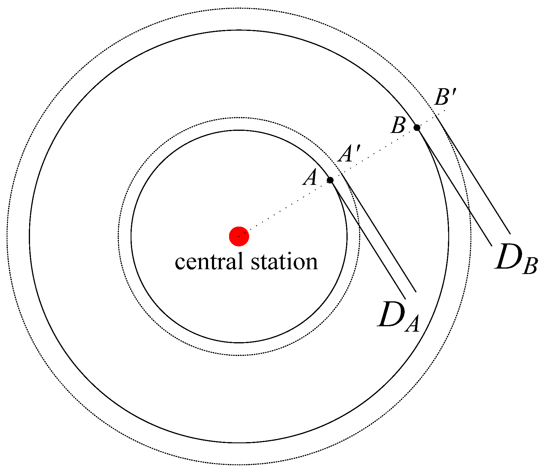
The comparison of the blue circle and green circle can clearly show the size and direction of the error, as seen in Figure 7. In the simulated lightning detection network, it is observed that the closer the location of the radiation source to be located is to the center of the hexagon formed by the seven detection stations, the smaller the simulation error, indicating more accurate positioning results. Consequently, we analyze the relationship between the distance of the positioning point from the center of the network of stations and the magnitude of the positioning error, i.e., the radial error.
The radial error is the difference between the distance dh from the radiation source to the center of the network and the distance dl from the positioning result of the radiation source to the center of the network. The assumed radiation source point and the located radiation source point are set as hypothetical point A (xA, yA, zA) and located point A′ (xA′, yA′, zA′).
Distance from radiation source point A to the center of the network:
d A = ( x A x 0 ) 2 + ( y A y 0 ) 2
A hypothetical radiating source point is positioned, incorporating a random time error within ±50 ns, to locate the distance from point A′ to the center of the network:
d A = ( x A x 0 ) 2 + ( y A y 0 ) 2
Radial error DA at the location of point A:
D A = | d A d A |
When the position of the radiation source is at point B, the positioning result is at B′ and the radial error DB at point B is obtained.
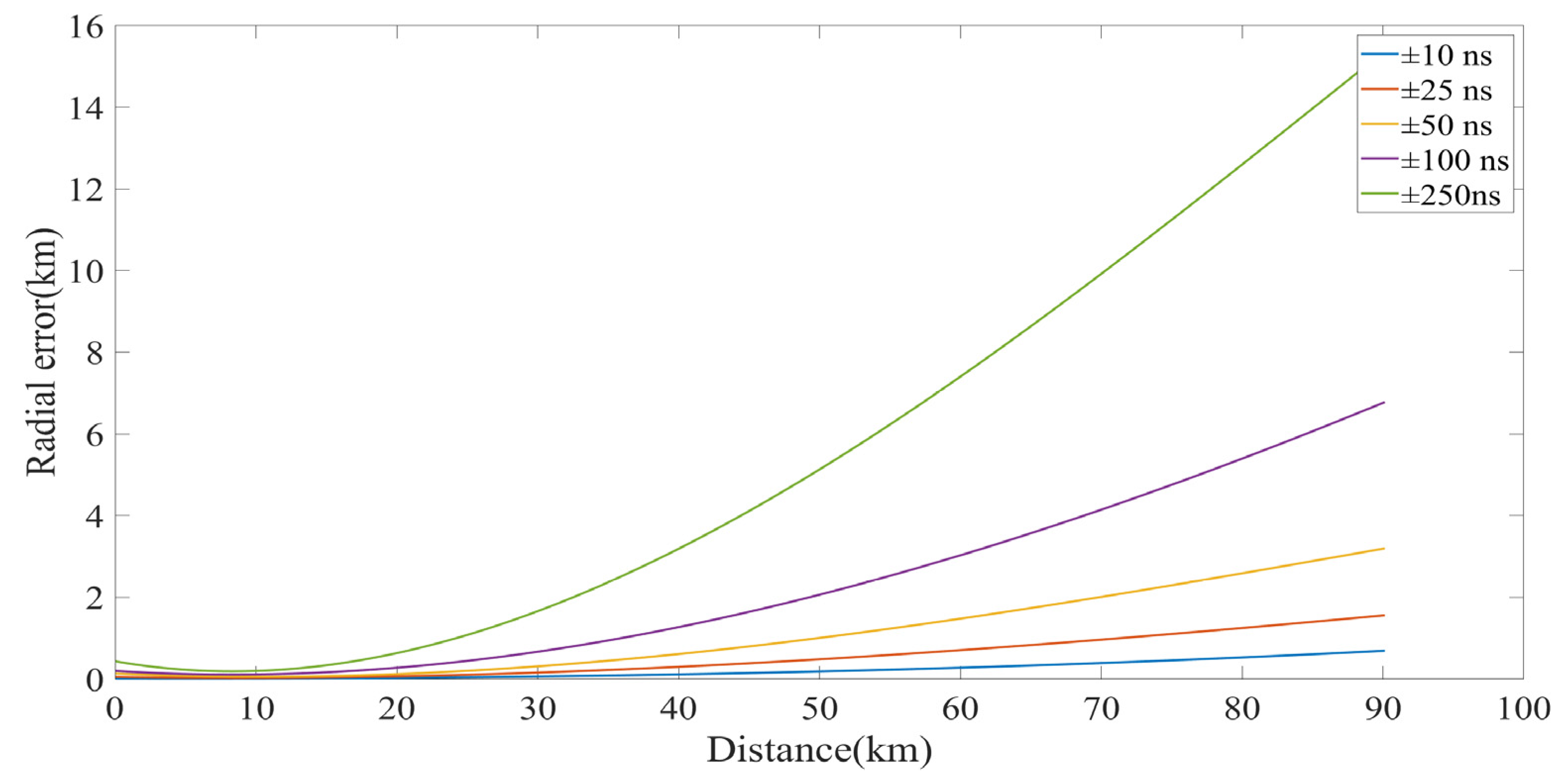
The non-time-synchronized flash positioning method involves the simultaneous positioning of two radiating sources. Initially, a random direction is selected in the first quadrant, and one of the radiating sources is placed in this direction, starting from the center of the network and progressively moving away from the positioning network in this direction. The other radiating source remains fixed and is referred to as a beacon point, with the assumption that the error of the beacon is negligible. As illustrated in Figure 8, one point (−20 km, −49 km, 6 km) is fixed, and another point gradually moves away from the center of the positioning network in the direction of (30 km, 20 km, 6 km). The simulated radial error with the distance is presented in Figure 9, considering double-pulse interval measurement errors of ±10 ns, ±25 ns, ±50 ns, ±100 ns, and ±250 ns, respectively.
As the radiation source gradually moves away from the positioning network, the radial error of its positioning point becomes larger and larger. Using the non-time-synchronized lightning method for radiation source positioning, the radial error of positioning is affected by the measurement error of the double-pulse interval, and the smaller the measurement error of the double-pulse interval, the smaller the radial error of radiation source positioning. For a positioning network with a baseline length of 10 km, when the measurement error of the pulse interval is less than ±25 ns, the radial error is less than 2 km within 90 km from the center of the positioning network.

5.2.1. Effect of Positional Error of Fixed-Coordinate Beacon Point on Positioning Results

To emphasize errors in the horizontal direction, we assumed a seven-station lightning detection network with a radius of 10 km. This network is arranged in a regular layout, featuring seven detection stations distributed in a positive hexagonal pattern around the central station. We simulated the positioning errors within a 100 × 100 km range centered around the central station. Within this range, 11 rows of positioning points were selected in the horizontal direction, with 10 km intervals between each row, and a similar selection was made in the vertical direction. A total of 2101 points at a height of 6 km were chosen for simulation, and their positioning errors were estimated.
The seven red points in Figure 10 and Figure 11 represent the locations of the lightning detection network stations. In the joint positioning of the non-time-synchronized lightning positioning method, one of the two radiation sources is fixed as a reference, acting as a fixed-coordinate beacon point. By introducing an error to the position of this beacon, we can analyze the impact of the positioning error of the lightning radiation source used as a reference on the positioning results.
As illustrated in Figure 10 and Figure 11, a random error of ±50 ns is added to the double-pulse interval. The coordinates of the beacon position are both (30 km, 30 km, 6 km). The positioning simulation is conducted by introducing position errors of 1 km and 3 km in each direction (east, south, west, and north) of the beacon, respectively. This allows for an analysis of the resulting positioning errors. Considering the limitations of the lightning detection network in practical positioning, and for convenience in discussing the effects of the relative positions of the beacon points on the positioning results, we determined the beacon points in the simulation process to be on the axis of the first quadrant at the position (30 km, 30 km, 6 km).
When utilizing a fixed-coordinate beacon point for joint positioning in the non-time-synchronized lightning positioning method, it becomes apparent that the positional error of the beacon point significantly impacts the accuracy of positioning. From the positioning results in Figure 10, we conclude that the maximum value of the error in the positioning result is 2.23 km and the minimum value is 0.012 km when the horizontal position error is given to the beacon point in four directions, due east, due south, due west, and due north, with a horizontal position error of 1 km. For Figure 10, the maximum value of the positioning error is 4.32 km and the minimum value is 0. 023 km. This impact is positively correlated with the positional error of the beacon, both in terms of direction and magnitude. The results obtained from this simulation corroborate the positioning outcomes depicted in Figure 4 in Section 4.

5.2.2. Effect of Relative Position of Fixed-Coordinate Beacon Point on Positioning Results

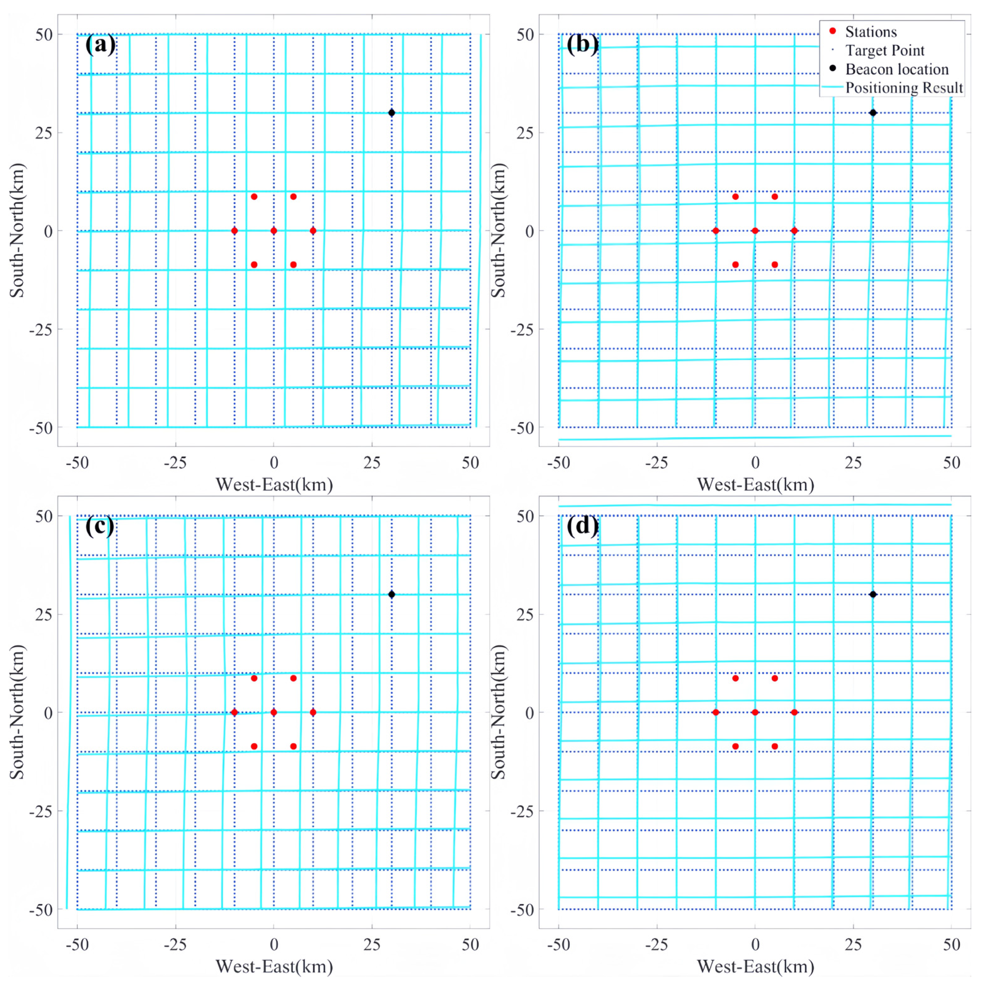
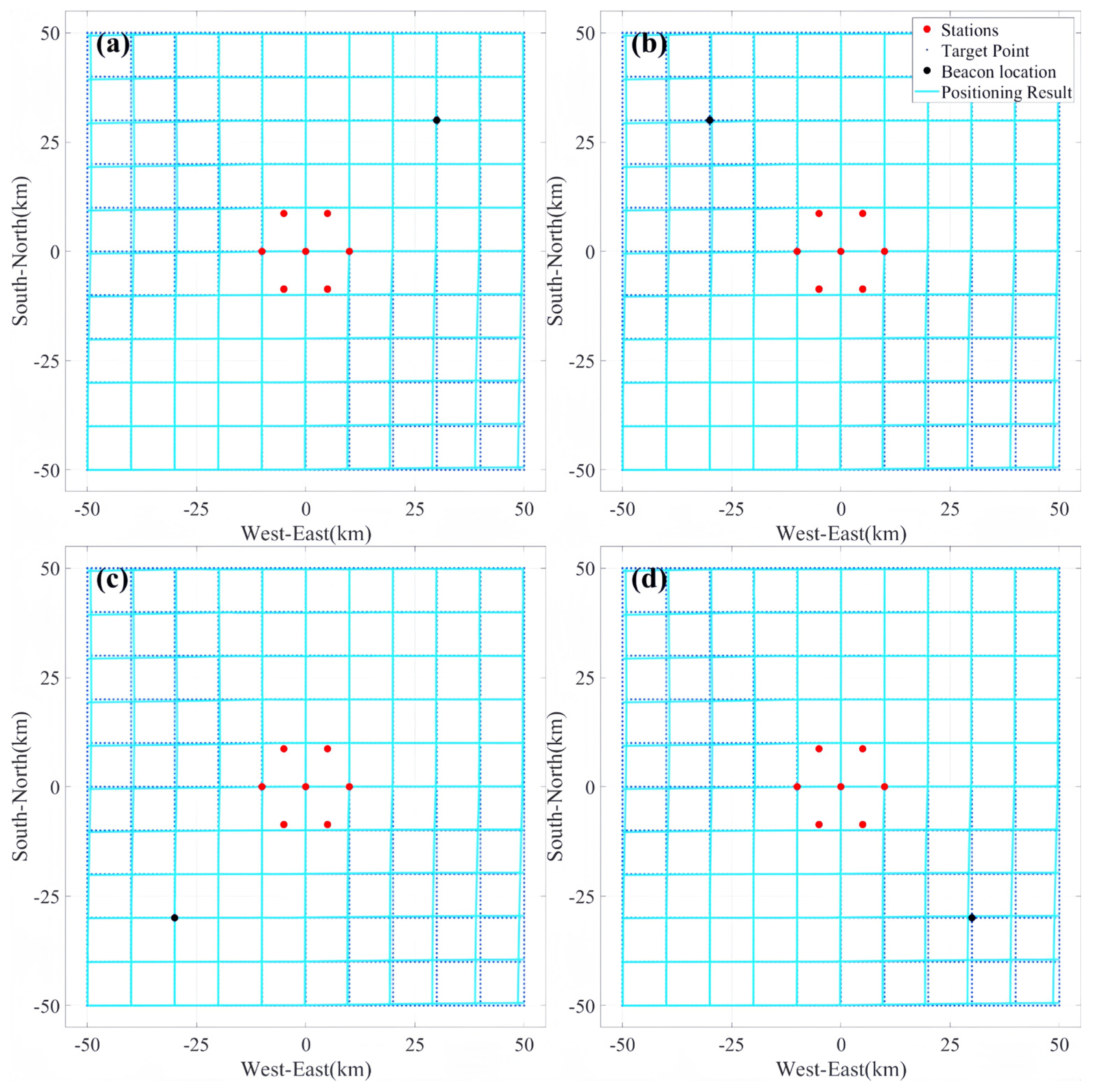
The seven red points in Figure 12 are the locations of the seven detection stations. The same method is used as in Section 5.2.1, but, here, we separate the four quadrants and position the beacons separately when they are in the first to fourth quadrant. This is used to simulate the positioning error when the beacons are in different quadrants.
For the simulated positioning with beacons in the first quadrant, joint positioning is performed using beacons with coordinates (30 km, 30 km, 6 km). For the simulated positioning of beacons in the second quadrant, the joint positioning is performed using beacons with coordinates (−30 km, 30 km, 6 km). For the simulated positioning of beacons in the third quadrant, joint positioning is performed using beacons with coordinates (−30 km, −30 km, 6 km). For the simulated positioning of beacons in the fourth quadrant, the joint positioning is performed using beacons with coordinates (30 km, −30 km, 6 km). The results of joint positioning in the four quadrants are shown in Figure 12a–d, respectively. The joint positioning beacons in the four quadrants are circularly symmetric with respect to the center coordinates.
Summarizing the simulation results above, it can be observed that the simulated positioning errors remain consistent when the joint positioning beacons are centrosymmetric about the central coordinates, and the maximum value of the error of the positioning is 1.284 km and the minimum value is 0.001 km. In the context of using the non-time-synchronized lightning positioning method for the positioning of radiation sources, the positioning accuracy remains largely unaffected even when the coordinate centers of individual radiation sources are transformed.

6. Conclusions

In traditional time-differential positioning systems [1,7], the errors come from the timing error of the GPS clock, the distortion caused by digitized sampling, the tropospheric delay error, and the cumulative error of the crystal frequency of the acquisition system [22], as well as the positional error of each detection station. Similarly, the non-time-synchronized lightning positioning method also has several types of errors beyond the GPS clock error. Since the non-time-synchronized 3D lightning positioning method does not rely on the time synchronization of the stations in the positioning system, the errors arising from the pursuit of time synchronization are removed, and it is possible to obtain higher positioning accuracy. In particular, under the condition that the frequency band of the acquired signal meets the requirements, the selection of acquisition card equipment with a higher sampling rate can effectively reduce the extraction error (i.e., digitization error) of the lightning signal, reduce the total error magnitude in the non-time-synchronized positioning method, and thus improve the positioning accuracy. In brief, it is possible for a non-time-synchronized positioning method to achieve better positioning accuracy when the quantization error of the data acquisition card is smaller than the timing error of the GPS.
The non-time-synchronized lightning positioning method is based on the joint positioning of two radiation sources using the time intervals of their pulse signals. It exploits the characteristic differences in the time intervals of the two radiation pulses received at seven stations, enabling the simultaneous positioning of both radiation sources. To further investigate the positioning effectiveness of the non-time-synchronized lightning positioning method, this study analyzes and refines the calculation results of individual cases using this method. Additionally, the study employs simulations to analyze the impact of a non-fixed beacon point, a fixed beacon point with errors, and the spatial location of the beacon point on the overall error distribution of the positioning results. The main conclusions are as follows.
  • In the non-time-synchronized lightning positioning method using two random radiation sources for joint positioning, there are uneven errors in the positioning results, and the positioning results can roughly reflect the lightning contours.
  • Similarly to the traditional positioning method, the farther away from the center of the positioning network, the larger the radial error of the positioning results. For a positioning network with a baseline length of 10 km, when the measurement error of the pulse interval is less than ±50 ns, the radial error is less than 2 km within 90 km from the center of the positioning network.
  • The positioning results when using a fixed-coordinate beacon point for joint positioning are similar to those of the traditional method, and the positional error of the beacon point affects the accuracy of positioning and is positively correlated with the positional error of the beacon point in terms of orientation and size.
  • The simulated positioning errors are basically the same when the joint beacon points are centrosymmetric about the center coordinates. In other words, when the non-time-synchronized lightning positioning method is utilized for radiation source positioning, the positioning accuracy is essentially unaffected when the coordinates of the beacon point are transformed.

Author Contributions

Data acquisition, Y.W. and L.Y.; software, Y.W. and L.Y.; validation, Y.W. and L.Y.; investigation, Y.M., Y.L. and G.Z.; writing—original draft preparation, Y.W. and L.Y.; writing—review and editing, Y.W., L.Y., Y.M., Y.L. and G.Z. All authors have read and agreed to the published version of the manuscript.

Funding

This work was funded by the Second Tibetan Plateau Scientific Expedition and Research (STEP) program of China (Project Number: 2019QZKK0104) and the National Natural Science Foundation of China (Approval Number: 41675006; 41875002).

Data Availability Statement

The data presented and the code from this paper are available on request from the corresponding author (Wang Yanhui).

Acknowledgments

We would like to sincerely thank the Zhang Guangshu Lightning Research Team of the Northwest Institute of Eco-Environmental Resources of the Chinese Academy of Sciences and the Public Technical Service Center of the Northwest Institute of Eco-Environmental Resources of the Chinese Academy of Sciences for their support and help in the field observation and data acquisition of this study.

Conflicts of Interest

The authors declare no conflicts of interest.

References

  1. Rison, W.; Thomas, R.J.; Krehbiel, P.R.; Hamlin, T.; Harlin, J. A GPS-based three-dimensional lightning mapping system: Initial observations in central New Mexico. Geophys. Res. Lett. 1999, 26, 3573–3576. [Google Scholar] [CrossRef]
  2. Smith, D.A.; Eack, K.B.; Harlin, J.; Heavner, M.J.; Jacobson, A.R.; Massey, R.S.; Shao, X.M.; Wiens, K.C. The Los Alamos Sferic Array: A research tool for lightning investigations. J. Geophys. Res. Atmos. 2002, 107, ACL 5-1–ACL 5-14. [Google Scholar] [CrossRef]
  3. Dowden, R.L.; Holzworth, R.H.; Rodger, C.J.; Lichtenberger, J.; Thomson, N.R.; Jacobson, A.R.; Lay, E.; Brundell, J.B.; Lyons, T.J.; O’Keefe, S.; et al. World-wide lightning location using VLF propagation in the Earth-ionosphere waveguide. IEEE Antennas Propag. Mag. 2008, 50, 40–60. [Google Scholar] [CrossRef]
  4. Betz, H.D.; Schmidt, K.; Laroche, P.; Blanchet, P.; Oettinger, W.P.; Defer, E.; Dziewit, Z.; Konarski, J. LINET—An international lightning detection network in Europe. Atmos. Res. 2009, 91, 564–573. [Google Scholar] [CrossRef]
  5. Zhang, G.; Wang, Y.; Qie, X.; Zhang, T.; Zhao, Y.; Li, Y.; Cao, D. Using lightning locating system based on time-of-arrival technique to study three-dimensional lightning discharge processes. Sci. China Earth Sci. 2010, 53, 591–602. [Google Scholar] [CrossRef]
  6. Zhang, G.; Li, Y.; Wang, Y.; Zhang, T.; Wu, B.; Liu, Y. Experimental study on location accuracy of a 3D VHF lightning-radiation-source locating network. Sci. China Earth Sci. 2015, 58, 2034–2048. [Google Scholar] [CrossRef]
  7. Sun, Z.; Qie, X.; Liu, M.; Cao, D.; Wang, D. Lightning VHF radiation location system based on short-baseline TDOA technique—Validation in rocket-triggered lightning. Atmos. Res. 2013, 129–130, 58–66. [Google Scholar] [CrossRef]
  8. Qie, X.; Liu, D.; Sun, Z. Recent advances in research of lightning meteorology. J. Meteorol. Res. 2014, 28, 983–1002. [Google Scholar] [CrossRef]
  9. Wang, D.; Xiushu, Q.; Tie, Y.; Guangshu, Z.; Tong, Z.; Tinglong, Z.; Qilin, Z. Analysis of the initial stage intracloud lightning using the pulse location technique based on the fast electric field change. J. Meteorol. Res. 2009, 23, 772–781. [Google Scholar]
  10. Wang, Y.; Qie, X.; Wang, D.; Liu, M.; Su, D.; Wang, Z.; Liu, D.; Wu, Z.; Sun, Z.; Tian, Y. Beijing Lightning Network (BLNET) and the observation on preliminary breakdown processes. Atmos. Res. 2016, 171, 121–132. [Google Scholar] [CrossRef]
  11. Srivastava, A.; Tian, Y.; Qie, X.; Wang, D.; Sun, Z.; Yuan, S.; Wang, Y.; Chen, Z.; Xu, W.; Zhang, H.; et al. Performance assessment of Beijing Lightning Network (BLNET) and comparison with other lightning location networks across Beijing. Atmos. Res. 2017, 197, 76–83. [Google Scholar] [CrossRef]
  12. Shi, D.; Zheng, D.; Zhang, Y.; Zhang, Y.; Huang, Z.; Lu, W.; Chen, S.; Yan, X. Low-frequency E-field Detection Array (LFEDA)—Construction and preliminary results. Sci. China Earth Sci. 2017, 60, 1896–1908. [Google Scholar] [CrossRef]
  13. Chen, Z.; Zhang, Y.; Zheng, D.; Zhang, Y.; Fan, X.; Fan, Y.; Xu, L.; Lyu, W. A Method of Three-Dimensional Location for LFEDA Combining the Time of Arrival Method and the Time Reversal Technique. J. Geophys. Res. Atmos. 2019, 124, 6484–6500. [Google Scholar] [CrossRef]
  14. Yuan, S.; Qie, X.; Jiang, R.; Wang, D.; Sun, Z.; Srivastava, A.; Williams, E. Origin of an Uncommon Multiple-Stroke Positive Cloud-to-Ground Lightning Flash with Different Terminations. J. Geophys. Res. Atmos. 2020, 125, e2019JD032098. [Google Scholar] [CrossRef]
  15. Wang, J.; Zhang, Y.; Tan, Y.; Chen, Z.; Zheng, D.; Zhang, Y.; Fan, Y. Fast and Fine Location of Total Lightning from Low Frequency Signals Based on Deep-Learning Encoding Features. Remote Sens. 2021, 13, 2212. [Google Scholar] [CrossRef]
  16. Wang, Y.; Min, Y.; Liu, Y.; Zhao, G. A New Approach of 3D Lightning Location Based on Pearson Correlation Combined with Empirical Mode Decomposition. Remote Sens. 2021, 13, 3883. [Google Scholar] [CrossRef]
  17. Wang, Y.; Min, Y.; Liu, Y.; Yao, L.; Liu, Y.; Guo, Z. A non-time-synchronized lightning positioning method and its preliminary application. Atmos. Res. 2023, 285, 106641. [Google Scholar] [CrossRef]
  18. Thomas, R.J.; Krehbiel, P.R.; Rison, W.; Hunyady, S.J.; Winn, W.P.; Hamlin, T.; Harlin, J. Accuracy of the Lightning Mapping Array. J. Geophys. Res. Atmos. 2004, 109, D14207. [Google Scholar] [CrossRef]
  19. Bitzer, P.M.; Christian, H.J.; Stewart, M.; Burchfield, J.; Podgorny, S.; Corredor, D.; Hall, J.; Kuznetsov, E.; Franklin, V. Characterization and applications of VLF/LF source locations from lightning using the Huntsville Alabama Marx Meter Array. J. Geophys. Res. Atmos. 2013, 118, 3120–3138. [Google Scholar] [CrossRef]
  20. Sun, Z.; Qie, X.; Liu, M. Characteristics of a Negative Cloud-to-Ground Lightning Discharge Based on Locations of VHF Radiation Sources. Atmos. Ocean. Sci. Lett. 2014, 7, 248–253. [Google Scholar] [CrossRef]
  21. Sun, Z.; Qie, X.; Liu, M.; Jiang, R.; Wang, Z.; Zhang, H. Characteristics of a negative lightning with multiple-ground terminations observed by a VHF lightning location system. J. Geophys. Res. Atmos. 2016, 121, 413–426. [Google Scholar] [CrossRef]
  22. Wang, Y.; Zhang, G.; Zhang, T.; Li, Y.; Fan, X.; Wu, B. Error Correction in Three-Dimension Location System of Lightning VHF Radiation. Plateau Meteorol. 2012, 31, 1407–1413. [Google Scholar]
  23. Zhao, J.Y.; Song, S.L.; Chen, Q.M.; Zhou, W.L.; Zhu, W.Y. Establishment of a new global model for zenith tropospheric delay based on functional expression for its vertical profile. Chin. J. Geophys. 2014, 57, 3140–3153. [Google Scholar] [CrossRef]
  24. Li, W.; Yuan, Y.; Ou, J.; Li, H.; Li, Z. A new global zenith tropospheric delay model IGGtrop for GNSS applications. Chin. Sci. Bull. 2012, 57, 2132–2139. [Google Scholar] [CrossRef]
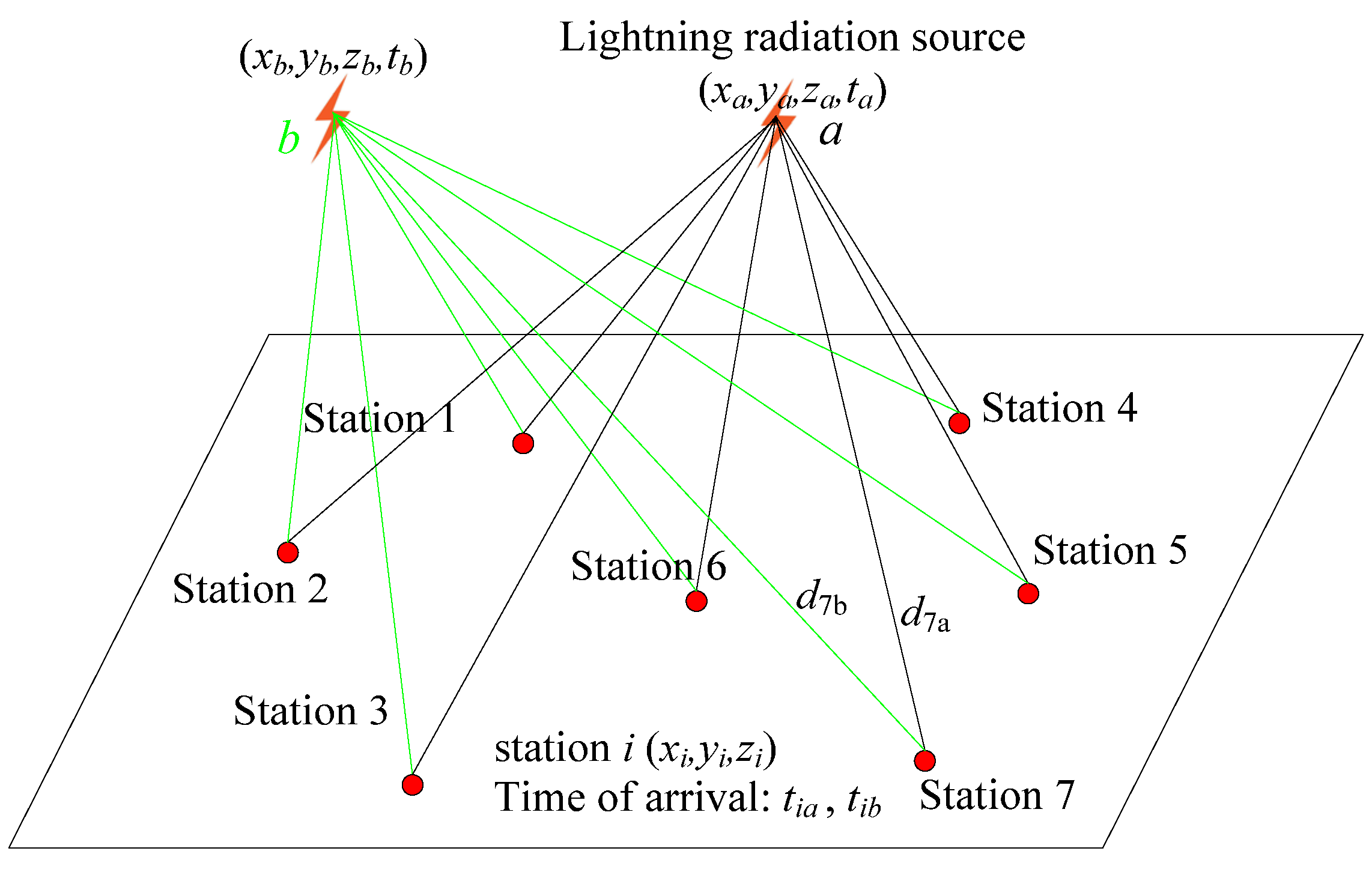
Figure 1. Schematic diagram of the non-time-synchronized lightning method of positioning.
Remotesensing 16 03443 g001
Figure 2. Schematic diagram of lightning signal extraction error.
Remotesensing 16 03443 g002
Figure 3. Comparison of positioning results between non-time-synchronized positioning method and time-difference arrival method. (TOA denotes “time difference of arrival”; DOPI denotes “difference of pulse interval”).
Remotesensing 16 03443 g003
Figure 4. Results of joint beacon point positioning based on non-time-synchronized method (beacon point: 192,685 m, −343,961 m, 4473 m).
Remotesensing 16 03443 g004
Figure 5. Plot of positioning results based on iterative computation of beacon point (beacon point: 191,864 m, −344,037 m, 4495 m).
Remotesensing 16 03443 g005
Figure 6. Schematic of simulated errors in non-fixed-coordinate beacon point.
Remotesensing 16 03443 g006
Figure 7. Schematic of simulated errors in non-time-synchronized lightning positioning with fixed-coordinate beacon point.
Remotesensing 16 03443 g007
Figure 8. Schematic diagram of radial error.
Remotesensing 16 03443 g008
Figure 9. Radial error for beacon point (−20 km, −49 km, 6 km), for (30 k, 20 k) direction.
Remotesensing 16 03443 g009
Figure 10. Horizontal positioning errors in a 100 km × 100 km square area with a height of 6 km, where vector errors are added to the black beacon point. The scenarios are as follows: (a) the beacon point is shifted by 1 km to the due east direction, (b) the beacon point is shifted by 1 km to the due south direction, (c) the beacon point is shifted by 1 km to the due west direction, and (d) the beacon point is shifted by 1 km to the due north direction.
Remotesensing 16 03443 g010
Figure 11. Horizontal positioning errors in a 100 km × 100 km square area with a height of 6 km, where vector errors are added to the black beacon point. The scenarios are as follows: (a) the beacon point is shifted by 3 km in the due east direction, (b) the beacon point is shifted by 3 km in the due south direction, (c) the beacon point is shifted by 3 km in the due west direction, and (d) the beacon point is shifted by 3 km in the due north direction.
Remotesensing 16 03443 g011
Figure 12. Horizontal positioning error (100 km × 100 km square area with 6 km height), transforming the quadrant where the beacon point is located: (a) the beacon point is located in the first quadrant with coordinates (30 km, 30 km, 6 km), (b) the beacon point is located in the second quadrant with coordinates (−30 km, 30 km, 6 km), (c) the beacon point is located in the third quadrant with coordinates (−30 km, −30 km, 6 km), (d) the beacon point is located in the fourth quadrant with coordinates (30 km, −30 km, 6 km).
Remotesensing 16 03443 g012
Disclaimer/Publisher’s Note: The statements, opinions and data contained in all publications are solely those of the individual author(s) and contributor(s) and not of MDPI and/or the editor(s). MDPI and/or the editor(s) disclaim responsibility for any injury to people or property resulting from any ideas, methods, instructions or products referred to in the content.