Communication

Virtual Array-Based Signal Detection and Carrier Frequency Offset Estimation in a Multistatic Collaborative Passive Detection System

School of Electronic Information and Communications, Huazhong University of Science and Technology, Wuhan 430074, China
*
Author to whom correspondence should be addressed.
Remote Sens. 2024, 16(17), 3152; https://doi.org/10.3390/rs16173152
Submission received: 11 July 2024 / Revised: 18 August 2024 / Accepted: 21 August 2024 / Published: 26 August 2024

Abstract

:
To tackle the problem of difficult signal detection and carrier frequency synchronization faced by wireless communication among stations of the multistatic passive detection system in interference environments, an adaptive signal detection and carrier frequency offset (CFO) estimation method based on a virtual array is proposed in this paper. This is a data-aided method that utilizes a training sequence composed of three segments of sub-training sequences with different symbols. This method first uses spatial spectrum estimation to obtain the coarse frequency estimations of interference signals and CFO from virtual array signals constructed from the first two sub-training sequences. Then, beamforming is conducted accordingly on the virtual array signals constructed from the third sub-training sequence to suppress the in-band interferences and protrude the expected signal. Finally, improved performance of signal detection and CFO estimation is obtained with the beamformed signals. Simulation experiments show that a missed detection probability as low as 1 × 10⁻⁴, with a false detection probability of 1 × 10⁻³, can be obtained under a signal-to-interference ratio (SIR) of −10 dB and Eb/N0 of 1 dB. Moreover, the proposed method can also simultaneously achieve a CFO estimation error that is lower than 3%, with the condition of Eb/N0 being as low as −5 dB under different SIRs. Simulation results validate the proposed method and demonstrate the promising application prospects of the proposed method in networked passive detection scenarios.

Graphical Abstract

1. Introduction

Networked detection with multi-stations is an important research direction in the field of passive detection [1,2], which is also an important means of improving passive detection performance [3,4,5]. Because of no signal transmitting, the passive detection system has to be deployed in an area with external illuminator of opportunities (IOs) to use their signals for target detection [6]. While these IOs provide signals for passive detection, they also bring inevitable interferences to the wireless communication among stations of the multistatic passive detection system (MPDS). Under such circumstance, apart from the expected signal, there could also be interferences and noises in the received baseband signal output by the receiver. For the out-band interferences, the low-pass filter is an effective means to suppress them. However, when the interferences fall into the passband, the filter-based method will fail. Thus, how to effectively detect signals and estimate carrier frequency offset (CFO) in the presence of in-band interferences is a key issue that affects the quality of wireless communication among stations of the MPDS, which is also an important factor that restricts network detection performance.
Spread spectrum communication technology is an important method for in-band interference suppression and is widely used in the field of communication [7,8,9]. Through encoding, spectrum spreading, and spectrum despreading, this technology can effectively mitigate the influence of in-band interferences on communication quality. However, such technology is bandwidth-demanding. In order to achieve spread spectrum communication, additional bandwidth greater than the information bandwidth is required, which is not conducive to mitigating the frequency congestion and improving the utilization efficiency of spectrum resources. With the rapid advancement of deep learning, the artificial intelligence-based method for in-band interference suppression has also been studied. Recently, a method based on a convolutional neural network and recurrent neural network with a gated recurrent unit for in-band interference suppression has been proposed in [10], which exhibits promising suppression performance in strong interference scenarios and is capable of effectively reducing the bit error rate. However, such a method demands a large amount of training data, which is not always available and will make the method hard to use in situations that require rapid deployment.
With the advantages of high estimation accuracy, low computational complexity, and ease of implementation, data-aided methods have become an important research direction for signal detection and CFO estimation in the field of communication. Such methods utilize the a priori information of the training sequence to construct timing metrics for signal detection, as well as to estimate CFO [11,12,13,14,15]. The most typical feature of such methods is that they generally construct timing metrics through the autocorrelation of the training sequence. In situations of high signal-to-noise ratio (SNR), it is easy to detect the timing of signal arrival through such timing metrics since the expected signal is much stronger than the noise. However, existing methods usually build the signal model without consideration of the impacts of in-band interferences. Thus, their performance in signal detection and CFO estimation cannot be ensured in the situation of networked passive detection in which interferences exist.
Through extensive simulation experiments, we find that when there are strong in-band interferences in the baseband signal; the timing metric constructed by autocorrelation can easily fail to distinguish the noise, interferences, and expected signal since the training sequence is disturbed, which could lead to a significant increment of false detection probability and missed detection probability. Consequently, the signal detection performance deteriorates. Thus, existing data-aided methods for signal detection will face the problem of performance degradation under low signal-to-interference ratio (SIR) and SNR circumstances. Meanwhile, such methods usually estimate CFO according to the characteristics of the phase shift between symbols in the training sequence. Similarly, their CFO estimation performance will also degrade as the signal phase is destructed by the in-band interferences.
To tackle the problem of performance degradation of existing methods in the presence of in-band interferences, we propose an adaptive signal detection and CFO estimation method based on virtual array technology in this paper. The virtual array is not a real existence but an equivalent array constructed based on the array signal model that is derived. With three sub-training sequences whose symbols are different, we first construct virtual array snapshots from the first two sub-training sequences and use the root-MUSIC algorithm [16] to perform virtual spatial spectrum estimation to obtain frequency estimations of the strong signals, which include in-band interferences and the expected signal. Then, we identify the frequencies corresponding to the in-band interferences and the expected signal according to the relationship between the frequency of the modulated signal and the symbol of the training sequence. On this basis, we further perform beamforming on the virtual array snapshots constructed from the third sub-training sequence to suppress the in-band interferences and protrude the expected signal. Finally, better signal detection and CFO estimation can be obtained by performing virtual spatial spectrum estimation on the beamformed signal. The feasibility and effectiveness of the proposed method are verified by theoretical analyses and simulation experiments, which show that the proposed method can detect signals with lower missed detection probability and false detection probability, as well as achieve higher CFO estimation accuracy compared to existing methods.
The rest of this paper is organized as follows: Section 2 presents the signal model. Section 3 introduces the principle of the proposed method for the construction of a virtual array signal and beamforming. Section 4 presents the results of simulation experiments. The conclusion is drawn in Section 5.

2. Signal Model

The minimum shift keying (MSK) signal possesses advantages such as high spectrum utilization, strong anti-interference ability, high transmission efficiency, and simple implementation, which is an effective means for inter-station communication in networked passive detection. According to [17], the model of the baseband receiving signal containing MSK signal, in-band interferences, CFO, and noise can be expressed as follows:
s ( t ) = c 0 e j 2 π Δ f t + a k π t 2 T b + φ k + m = 1 M s m ( t ) + w ( t ) ,
where c 0 is the signal magnitude at time t, Δ f is the CFO, a k is the kth symbol, T b is the symbol period, φ k is the initial phase of the kth symbol, s m ( t ) is the m-th in-band interference, M is the total number of in-band interferences, and w ( t ) is white Gaussian noise. Assume the M in-band interferences are uncorrelated with each other and are all uncorrelated with the expected signal. Without the loss of generality, we take the narrow band interferences as an example to conduct theoretical derivation and analysis. Under such circumstances, the signal model of the in-band interferences can be written as follows:
s m ( t ) = c m e j [ 2 π ( f m + Δ f ) t + φ m ] , 1 m M ,
where c m , f m , and φ m are the amplitude, baseband frequency, and initial phase of the m-th in-band interference, respectively.
In the MSK signal, the initial phases of any two adjacent symbols satisfy the following relationship:
φ k = φ k 1 + k π 2 ( a k 1 a k ) .
We can infer from (1) and (3) that the signal phase is linear in a period of time corresponding to a segment of homopolar symbols, which shows the same characteristics as the phase of a snapshot of the array signal and lays the foundation of utilizing array signal processing algorithms in communication signal processing.
In the digital domain, the baseband receiving signal can be rewritten as follows:
s ( n ) = c 0 e j 2 π Δ f n T s + a k π n T s 2 T b + φ k + m = 1 M c m e j [ 2 π ( f m + Δ f ) n T s + φ m ] + w ( n ) ,
where s ( n ) is the sampled sequence of the baseband receiving signal, n(=1, 2, 3, …) is the sampling number, T s (= T b / N s , N s is the number of points sampled in one symbol period) is the sampling period, and w ( n ) is the sampled sequence of white Gaussian noise. Let f 0 = a k / ( 4 T b ) and φ 0 = φ k , and then (4) can be rewritten as follows:
s ( n ) = m = 0 M c m e j [ 2 π ( f m + Δ f ) n T s + φ m ] + w ( n ) ,
where f 0 is the baseband frequency of the MSK signal. Then, let Δ φ C F O = 2 π Δ f T s and Δ φ m = 2 π f m T s , and we call Δ φ C F O and Δ φ m the additional phase induced by CFO and the additional phase corresponding to the baseband frequency of each signal component, respectively. In particular, when m = 0, the corresponding Δ φ 0 denotes the additional phase induced by the MSK modulation. On this basis, (5) can be rewritten as follows:
s ( n ) = m = 0 M c m e j n Δ φ m + n Δ φ C F O + φ m + w ( n ) .
Based on the above signal model, we propose a data-aided method for signal detection and CFO estimation for wireless communication among stations of MPDSs in this paper. The method takes advantage of the frequency characteristic of the MSK signal and designs the training sequence as a three-segment sequence with a structure of +AA+A, where A represents the repeated part and we call it a sub-training sequence. To improve the readability of this paper, we summarize the proposed method in the following paragraph before explaining the key parts in detail.
Firstly, we construct virtual array snapshots from the first two sub-training sequences. Then, with the root-MUSIC algorithm, we obtain the coarse estimations of the “interference frequencies + CFO” and the “expected signal frequency + CFO”. Next, we construct new virtual array snapshots from the third sub-training sequence and perform beamforming on them according to the previous frequency estimations, i.e., form virtual beam at the “expected signal frequency + CFO” and form beam nulls at “interference frequencies + CFO” to suppress the in-band interferences and protrude the expected signal. Finally, we reuse the root-MUSIC algorithm to process the beamformed data. From the obtained roots, we pick the one that is nearest to the unit circle and take its amplitude as the metric to determine whether the signal is arriving or not. If so, we extract its phase to calculate the CFO and take the left endpoint of the current time window as the coarse estimation of the starting position of the burst frame.

3. Derivation of the Proposed Method

3.1. Construction of Virtual Array Signal Model

Assume that the length of the signal sequence fragment in each time window is N w samples. We first pick a subsequence of length L from it with indices generated according to the combinatorics theory, i.e., the indices are a combination obtained by arbitrarily picking L numbers from the sequence of {1, 2, …, Nw}. Assume the index combination is i 1 = { i 1 ( l ) : l = 1, 2, …, L}, and the resulting subsequence is s 1 = { s 1 ( l ) : l = 1 , 2 , , L } , where
s 1 ( l ) = m = 0 M c 1 ( m ) e j { [ i 1 ( l ) i 1 ( 1 ) ] ( Δ φ C F O + Δ φ m ) + φ 1 ( m ) } + w 1 ( l ) ,
where c 1 ( m ) and φ 1 ( m ) denote the amplitude and phase of the m-th signal component in the first signal sample of the subsequence, respectively, [ i 1 ( l ) i 1 ( 1 ) ] ( Δ φ C F O + Δ φ m ) is the phase difference of the m-th signal component in the l-th signal sample relative to the same signal component in the first signal sample of the subsequence, and w 1 ( l ) is the white Gaussian noise in the l-th signal sample. Let Δ i l = i 1 ( l ) i 1 ( 1 ) , and then (7) can be rewritten as follows:
s 1 ( l ) = m = 0 M c 1 ( m ) e j [ Δ i l ( Δ φ C F O + Δ φ m ) + φ 1 ( m ) ] + w 1 ( l ) .
Then, we add (P−1) constants to i 1 in the way of i p = i 1 + ( p 1 ) Δ n s , where p = 2, 3, …, P and Δ n s is a constant, and we will obtain another (P−1) index combinations. With these index combinations, we pick out another (P−1) subsequences from the original signal sequence fragment. Since the phase of this signal sequence fragment is linear, as mentioned in Section 2, it is obvious that any signal component contained in a signal sample in the (P−1) subsequences can be regarded as a result of the same component in the corresponding signal sample of the first subsequence shifting a phase of Δ φ p = ( p 1 ) Δ n s ( Δ φ C F O + Δ φ m ) , p = 2, 3, …, P. Thus, the other (P−1) signal subsequences can be denoted as s p = { s p ( l ) : l = 1 , 2 , , L } , p = 2, 3, …, P, where
s p ( l ) = s 1 ( l ) e j ( p 1 ) Δ n s ( Δ φ C F O + Δ φ m ) = m = 0 M c 1 ( m ) e j [ Δ i l ( Δ φ C F O + Δ φ m ) + φ 1 ( m ) ] e j ( p 1 ) Δ n s ( Δ φ C F O + Δ φ m ) + w p ( l ) .
Since Δ φ 0 is known, we can compensate for this phase component in the signal and then integrate each subsequence to improve the SNR. The resulting signal of each subsequence can be expressed as follows:
s ( p ) = l = 1 L s p ( l ) e j Δ i l Δ φ 0 = l = 1 L m = 0 M c 1 ( m ) e j [ Δ i l ( Δ φ C F O + Δ φ m Δ φ 0 ) + φ 1 ( m ) ] e j ( p 1 ) Δ n s ( Δ φ C F O + Δ φ m ) + l = 1 L w p ( l ) e j Δ i l Δ φ 0 = m = 0 M e j ( p 1 ) Δ n s ( Δ φ C F O + Δ φ m ) c 1 ( m ) e j φ 1 ( m ) l = 1 L e j Δ i l ( Δ φ C F O + Δ φ m Δ φ 0 ) + l = 1 L w p ( l ) e j Δ i l Δ φ 0 ,
where p = 1, 2, 3, …, P. On this basis, let
s = ( s ( 1 ) , s ( 2 ) , , s ( P ) ) T ,
x = [ x ( 0 ) , x ( 1 ) , , x ( M ) ] T = c 1 ( 0 ) e j φ 1 ( 0 ) l = 1 L e j Δ i l Δ φ C F O c 1 ( 1 ) e j φ 1 ( 1 ) l = 1 L e j Δ i l ( Δ φ C F O + Δ φ 1 Δ φ 0 ) c 1 ( M ) e j φ 1 ( M ) l = 1 L e j Δ i l ( Δ φ C F O + Δ φ M Δ φ 0 ) ,
B = [ b ( 0 ) , b ( 1 ) , , b ( M ) ] T = 1 1 1 e j Δ n s ( Δ φ C F O + Δ φ 0 ) e j Δ n s ( Δ φ C F O + Δ φ 1 ) e j Δ n s ( Δ φ C F O + Δ φ M ) e j ( P 1 ) Δ n s ( Δ φ C F O + Δ φ 0 ) e j ( P 1 ) Δ n s ( Δ φ C F O + Δ φ 1 ) e j ( P 1 ) Δ n s ( Δ φ C F O + Δ φ M ) ,
w = [ w ( 1 ) , w ( 2 ) , , w ( P ) ] T = l = 1 L w 1 ( l ) e j Δ i l Δ φ 0 l = 1 L w 2 ( l ) e j Δ i l Δ φ 0 l = 1 L w P ( l ) e j Δ i l Δ φ 0 ,
then, (10) can be rewritten as follows:
s = B x + w .
We can see that (15) has the general form of an array signal, which means that we obtain a virtual array using the above derivation. Thus, we call s the constructed virtual array snapshot, B the virtual array manifold, x the virtual signal source vector, and w the virtual noise vector. Repeat above steps N s n times, and we will obtain N s n virtual array snapshots.
Using the constructed snapshots for virtual spatial spectrum estimation, we can obtain M+1 frequency estimations of the M+1 virtual signal sources, i.e., M in-band interferences and one expected signal. By utilizing the influence of the symbol polarity on the MSK signal frequency, we can distinguish the frequency component of the expected signal from those of the in-band interferences from the frequency estimations obtained with the virtual array snapshots constructed from the first two sub-training sequences.
According to (13), it can be inferred that when the symbol polarity is positive in the sub-training sequence, the frequencies of the virtual signal sources that can be estimated from virtual spatial spectrum estimation are Δ f ^ + f ^ 0 , Δ f ^ + f ^ 1 , …, Δ f ^ + f ^ M , whereas, when the symbol polarity is negative, the corresponding frequency estimations that can be obtained are Δ f ^ f ^ 0 , Δ f ^ + f ^ 1 , …, Δ f ^ + f ^ M . Thus, according to the difference between frequency estimations obtained from the first two sub-training sequences, it is easy to distinguish the “expected signal frequency + CFO” from the “interference frequencies + CFO”.

3.2. Virtual Beamforming

On the above basis, we further construct new virtual array snapshots from the third sub-training sequence. Then, we form a virtual beam at the virtual source frequency corresponding to the “expected signal frequency + CFO” and form beam nulls at the virtual source frequencies corresponding to “interference frequencies + CFO” to suppress the in-band interferences. Given that the expected signal is not significantly stronger than the in-band interferences in an interference environment, we use the diagonal-loaded minimum variance distortionless response (MVDR) algorithm [18] to form the virtual beam.
We first divide the virtual array into several sub-arrays and then perform beamforming in each sub-array. We divide the array in a uniform and overlapping manner. Assume the number of elements in each sub-array is P s u b and the number of nonoverlapping elements between two adjacent sub-arrays is P i n d , and then we can divide the original virtual array into Q ( = P P s u b + P i n d ) sub-arrays. The weighting vector for beamforming in each sub-array is as follows:
h b f = M 1 a b f 0 a b f 0 H M 1 a b f 0 ,
where M = R ^ x x + α I denotes the diagonal-loaded interference covariance matrix of the sub-array, R ^ x x is the interference covariance matrix of the sub-array, α is the loading coefficient, and a b f 0 is the virtual steering vector that directs to Δ f ^ + f ^ 0 , which is expressed as a b f 0 = [ 1 , e j 2 π Δ n s T s ( Δ f ^ + f ^ 0 ) , , e j 2 π ( P s u b 1 ) Δ n s T s ( Δ f ^ + f ^ 0 ) ] T .
After beamforming in each sub-array, the resulting signal can be expressed as follows:
y q , n s n = h b f T s q , n s n ,
where q = 1, 2, …, Q is the serial number of the sub-array, Q is the total number of sub-arrays, and s q , n s n denotes the nsn-th virtual snapshot of the q-th sub-array. Then we form the beamformed signals from those sub-arrays into a new virtual array snapshot, which can be expressed as y n s n = [ y 1 , n s n , y 2 , n s n , , y Q , n s n ] T .
From the above derivation, it is easy to know that in any two adjacent sub-virtual array snapshots that are divided from the original virtual array snapshot, the phase difference between the same signal components contained in two corresponding elements is P i n d Δ n s ( Δ φ C F O + Δ φ m ) . Thus, the array manifold of the up-level virtual array formed by the aforementioned sub-arrays can be expressed as follows:
B u p A r y = 1 1 1 e j P i n d Δ n s ( Δ φ C F O + Δ φ 0 ) e j P i n d Δ n s ( Δ φ C F O + Δ φ 1 ) e j P i n d Δ n s ( Δ φ C F O + Δ φ M ) e j ( Q 1 ) P i n d Δ n s ( Δ φ C F O + Δ φ 0 ) e j ( Q 1 ) P i n d Δ n s ( Δ φ C F O + Δ φ 1 ) e j ( Q 1 ) P i n d Δ n s ( Δ φ C F O + Δ φ M ) .
Then, we use the root-MUSIC algorithm to process the new virtual array snapshots obtained from virtual beamforming to realize signal detection and CFO estimation. Assume the root that is nearest to the unit circle is z 0 , and then signal detection can be realized based on whether the distance between z 0 and the unit circle is less than the given threshold or not. If so, the coarse estimation of the starting position of the burst frame can be estimated as the left endpoint of the current time window. Meanwhile, the CFO estimation can be calculated according to (18) as follows:
Δ f e s t = arg ( z 0 ) 2 π P i n d Δ n s T s a k 4 T b .
Additionally, according to the abovementioned derivation and the computational complexity of the root-MUSIC algorithm [19], we can find that the number of operations for the proposed method is from the order of O (4Nsn + 2P3 + Q3).

4. Simulation Results

Simulation experiments are conducted to validate the performance of signal detection and CFO estimation of the proposed method. The results and analyses are presented in this section. In addition, in order to show the superiority of the proposed method in signal detection and CFO estimation, performance comparisons between the published methods in [11,12,13,14,15] and ours are also made in this section under the same simulation conditions.
The parameters used for simulation experiments are listed in Table 1. Moreover, the modulation type used in our simulation experiments is MSK. The signal channel is a narrowband interference channel under the condition of networked passive detection. The total length of the three-segment training sequence is 60 symbols, with 20 symbols for each subsequence.
It is worth mentioning that the parameters listed in Table 1 are fixed ones that will not be changed in all simulation experiments. Those not listed such as Eb/N0 and SIR vary in different experiments and will be provided later.

4.1. Performance Analysis of Signal Detection

Figure 1 shows the statistical results of the false detection probability, which is expressed as P F D , and the missed detection probability, which is expressed as P M D , of the proposed method under different Eb/N0s and SIRs. For the purpose of clarity, we plot the results corresponding to SIR = −10 dB, −6 dB, and −2 dB in Figure 1a–c, respectively. It should be noted that the P F D and P M D corresponding to each Eb/N0 and SIR are statistical results of 1 × 10⁵ repeated trials. Moreover, due to the use of logarithmic coordinate in the vertical axis, when the calculated P F D or P M D is 0, its logarithmic value becomes infinitesimal and cannot be seen in the figure. Thus, some curves in Figure 1a–c are interrupted before reaching the high Eb/N0 end.
It can be seen from the solid curves marked with “+” in Figure 1a–c that the P F D is almost unchanged when the Eb/N0 increases in the range of [−5, 11] dB in each figure, which corresponds to a fixed SIR. Especially, under the circumstance of SIR = −2 dB and Eb/N0 = −5 dB, the proposed method can achieve a P F D as low as 3 × 10⁻³, as shown in Figure 1c. Moreover, we can also find that the false detection probability of the proposed method remains almost unchanged when the SIR decreases under the same Eb/N0. As shown in Figure 1a,c, for the situation of Eb/N0 = −5 dB, the false detection probability is about 4 × 10⁻³ for SIR = −10 dB, and as the SIR increases to −2 dB, the P F D only decreases to 3 × 10⁻³ for the same Eb/N0. It can be demonstrated from the abovementioned results that the false detection probability of the proposed method is insensitive to both the SIR and Eb/N0 in the given range.
From the dashed curves marked with “+” in three figures of Figure 1, we can see that the missed detection probability P M D decreases as the Eb/N0 increases under the same SIR. As shown in Figure 1a, the P M D decreases from 3 × 10⁻¹ to 1 × 10⁻⁴, with the Eb/N0 increasing from −5 dB to 1 dB. Moreover, we can also see that in the given SIR range, the P M D of the proposed method remains almost unchanged when the SIR increases under the same Eb/N0. As shown in Figure 1a, under the situation of Eb/N0 = −1 dB, the P M D of the proposed method is about 2 × 10⁻³ for SIR = −10 dB, whereas with the SIR increasing to −2 dB, the P M D only decreases to 1.3 × 10⁻³, as shown in Figure 1c. These results indicate that the missed detection probability of the proposed method is sensitive to Eb/N0 but insensitive to SIR in the given range.
To sum up, the results shown in Figure 1 demonstrate the good performance of the proposed method in signal detection under the situations of low SIR and low Eb/N0.
In addition, in order to further show the superiority of the proposed method in signal detection, we conduct simulation experiments under the same conditions mentioned before using methods published in [11,12,13,14] and plot their results in Figure 1 together for the convenience of comparison.
We can see from the solid lines in Figure 1a–c that the false detection probability of the proposed method is lower than those of the methods published in [11,13,14]. Under the situation with relatively high Eb/N0, the false detection probability of the proposed method is higher than that of the method in [12]. However, it can also be seen from the corresponding missed detection probability that the low false detection probability of the method in [12] is achieved at the cost of a very high missed detection probability. Thus, even though the false detection probability of the method in [12] is lower than that of the proposed method under higher Eb/N0, its corresponding missed detection probability is much higher than that of the proposed method, which indicates that the signal detection performance of the method in [12] is not better than the proposed method under low SIR and Eb/N0.
In addition, we can also see from the dashed lines in the three figures of Figure 1 that the missed detection probability of the proposed method is the lowest among these methods, except the one published in [11] under different SIRs and Eb/N0s. For the method published in [11], we can see from Figure 1a,b that its missed detection probability is the lowest under the situations of SIR = −10 dB and −6 dB. However, we can also see that the corresponding false detection probabilities of this method are almost 1, which indicates that its low missed detection probability is achieved at the cost of a very high false detection probability. Thus, the signal detection performance of the method in [11] is also not better than the proposed method under the low SIR and Eb/N0.
To sum up, we can conclude that the signal detection performance of the proposed method is the best compared to the published ones, which demonstrates the good application prospects of the proposed method in interference environments.

4.2. Performance Analysis of CFO Estimation

We use the mean relative error (MRE) to evaluate the CFO estimation performance of the proposed method, which is defined as follows:
M R E = 1 N t n t = 1 N t Δ f e s t ( n t ) Δ f t r u e Δ f t r u e × 100 % ,
where Δ f e s t ( n t ) is the CFO estimation obtained in the n t -th correct detection, N t is the total number of correct detections, and Δ f t r u e is the true value of the CFO.
Figure 2 shows the MRE curves of the proposed method obtained under different SIRs and Eb/N0s. Similar to Figure 1, the MRE obtained under each SIR and Eb/N0 is the statistical result obtained with 1 × 10⁵ repeated experiments.
It can be seen from the curves marked with “+” in Figure 2a–c that the proposed method can achieve a CFO estimation error that is lower than 3% with the condition of Eb/N0 being as low as −5 dB under different SIRs. In addition, when the SIR is fixed, the MRE can be further lowered as the Eb/N0 increases. As shown in the three figures of Figure 2, the CFO estimation error of the proposed method can reach a level that is lower than 0.5% when the Eb/N0 increases to 11 dB. These results indicate that the proposed method is effective for estimating CFO in situations with low SIR and low Eb/N0, and the estimation accuracy is high, which demonstrates the promising application prospects of the proposed method in interference environments.
Similarly, a comparison of the CFO estimation performance among published methods and the proposed method is also made under the same conditions. The MREs obtained with the published methods are also shown in Figure 2 for the convenience of comparison. It should be noted that since the MRE is calculated under the condition of correct signal detection, there will be no MRE calculated when the missed detection probability is 1 because the algorithm detects no signals. Under such circumstances, there will also be no curves plotted in the figure. What is more, because the methods published in [12,14] do not include CFO estimation, we combine them with the CFO estimation method published in [15] to conduct the simulation experiments, which is realized by using the method in [15] to estimate CFO on the basis of the signal detected using the methods in [12,14].
From comparisons made in the three figures of Figure 2, we can find that the proposed method possesses the lowest MRE among the five methods under different SIRs and Eb/N0s. Moreover, for SIR = −10 dB and −6 dB, the MREs of the proposed method are much lower than those of the other four methods. Results shown in Figure 2 imply that the CFO estimation performance of the proposed method is superior to the published methods, and such superiority is more obvious in lower SIR and Eb/N0 situations.

5. Discussion

In the simulation experiments, we use three sub-training sequences whose lengths are 20 symbols to form the training sequence. As a matter of fact, the length of the sub-training sequence can be adjusted according to the communication overhead that is available in the MPDS and the complexity of the application environment. We can learn from the construction method for virtual array signals introduced in Section 3.1 that the length of the training sequence not only determines the aperture of the virtual array but also determines the number of virtual array snapshots to be constructed. For a fixed length of the training sequence, a large virtual array aperture means a small amount of virtual array snapshots. Generally, to ensure the effectiveness of the covariance matrix estimation in the root-MUSIC algorithm, the number of virtual array snapshots cannot be too small. Thus, under such a precondition, we need to make a compromise between the communication overhead of the MPDS and the performance of the proposed method to determine a suitable length for the training sequence. Although a long training sequence is beneficial to construct a large virtual array aperture that has more array degrees of freedom to suppress in-band interferences, it also brings problems of raising communication overhead and computational complexity. In general, while ensuring a certain level of communication quality, it is better to choose a shorter training sequence based on the complexity of environmental interferences in the passive detection scenario to lower the communication overhead, which is an appropriate way that we would like to suggest.

6. Conclusions

Addressing the problem of difficult signal detection and CFO estimation faced by the inter-station communication of MPDSs in interference environments, a method for signal detection, starting position estimation, and CFO estimation is proposed based on a virtual array in this paper. It is a data-aided method that uses a three-segment training sequence. It first implements coarse signal detection and CFO estimation from virtual array snapshots constructed from the first two sub-training sequences. Then, the virtual beamforming technique is introduced to process the virtual array snapshots constructed from the third sub-training sequence to protrude the expected signal and suppress the in-band interferences, which is beneficial to improve signal detection performance and CFO estimation accuracy. The simulation results show that the proposed method can achieve very low missed detection probability and false detection probability, as well as achieve very high CFO estimation accuracy in the situations of low SIR and Eb/N0, which validates the proposed method and shows its promising application prospects in networked passive detection scenarios.

Author Contributions

Conceptualization, methodology, validation, writing—original draft preparation and editing, X.C.; writing—review and supervision, H.M.; verification of results, H.Z. and J.J. All authors have read and agreed to the published version of the manuscript.

Funding

This research was funded by the China Postdoctoral Science Foundation, grant number 2023M731211, and by the National Natural Science Foundation of China, grant number 62071188.

Data Availability Statement

The original contributions presented in this study are included in the article, and further inquiries can be directed to the corresponding author.

Conflicts of Interest

The authors declare no conflicts of interest.

References

  1. Wan, X.; Yi, J.; Zhan, W.; Xie, D.; Shu, K.; Song, J.; Cheng, F.; Rao, Y.; Gong, Z.; Ke, H. Research progresses and development trends of the multi-illuminator-based passive radar. J. Radars 2020, 9, 939–961. [Google Scholar]
  2. Zhe, G. Evolution of netted radar systems. IEEE Access 2020, 8, 124961–124977. [Google Scholar]
  3. Zaimbashi, A. Multistatic passive radar sensing algorithms with calibrated receivers. IEEE Sens. J. 2020, 20, 7878–7885. [Google Scholar] [CrossRef]
  4. Cao, X.; Yi, J.; Gong, Z.; Wan, X. Automatic target recognition based on RCS and angular diversity for multistatic passive radar. IEEE Trans. Aerosp. Electron. Syst. 2022, 58, 4226–4240. [Google Scholar] [CrossRef]
  5. Cao, X.; Yi, J.; Gong, Z.; Wan, X. Automatic target recognition combining angular diversity and time diversity for multistatic passive radar. Sci. China-Inf. Sci. 2022, 65, 179303:1–179303:2. [Google Scholar] [CrossRef]
  6. Kuschel, H.; Cristallini, D.; Olsen, K.E. Tutorial: Passive radar tutorial. IEEE Aerosp. Electron. Syst. Mag. 2019, 34, 2–19. [Google Scholar] [CrossRef]
  7. Pickholtz, R.; Schilling, D.; Milstein, L. Theory of spread- spectrum communications—A tutorial. IEEE Trans. Commun. 1982, 30, 855–884. [Google Scholar] [CrossRef]
  8. Haab, D.B.; Sego, T.C.; Holschuh, T.V.; Moradi, H.; F-Boroujeny, B. Multicode signaling in a filter bank multicarrier spread spectrum system and its application to HF communications. IEEE Open J. Commun. Soc. 2023, 4, 442–455. [Google Scholar] [CrossRef]
  9. Nadi, M.; Cheldavi, A. Secure communication enabled by time-modulated metasurface antenna based on spread-spectrum technique. IEEE Antennas Wirel. Propag. Lett. 2024, 23, 1144–1148. [Google Scholar] [CrossRef]
  10. Wang, Y.; Luo, Z.; Wang, X. A CNN-GRU based approach for strong in-band interference mitigation in wireless communication systems. In Proceedings of the 2023 2nd International Conference on Computing, Communication, Perception and Quantum Technology (CCPQT), Xiamen, China, 4–7 August 2023. [Google Scholar]
  11. Minn, H.; Bhargava, V.K.; Letaief, K.B. A robust timing and frequency synchronization for OFDM systems. IEEE Trans. Wirel. Commun. 2003, 2, 822–839. [Google Scholar] [CrossRef]
  12. Abdzadeh-Ziabari, H.; Zhu, W.-P.; Swamy, M.N.S. Improved coarse timing estimation in OFDM systems using high-order statistics. IEEE Trans. Commun. 2016, 64, 5239–5253. [Google Scholar] [CrossRef]
  13. Schmidl, T.M.; Cox, D.C. Robust frequency and timing synchronization for OFDM. IEEE Trans. Commun. 1997, 45, 1613–1621. [Google Scholar] [CrossRef]
  14. Zhang, J.; Huang, X.J. Autocorrelation based coarse timing with differential normalization. IEEE Trans. Wirel. Commun. 2012, 11, 526–530. [Google Scholar] [CrossRef]
  15. Singh, P.; Sharma, E.; Vasudevan, K.; Budhiraja, R. CFO and channel estimation for frequency selective MIMO-FBMC/OQAM systems. IEEE Wirel. Commun. Lett. 2018, 7, 844–847. [Google Scholar] [CrossRef]
  16. Rao, B.D.; Hari, K.V.S. Performance analysis of root-MUSIC. IEEE Trans. Acoust. Speech Signal Process. 1989, 37, 1939–1949. [Google Scholar] [CrossRef]
  17. Gudovskiy, D.A.; Chu, L.; Lee, S. A novel nondata-aided synchronization algorithm for MSK-type-modulated signals. IEEE Commun. Lett. 2015, 19, 1552–1555. [Google Scholar] [CrossRef]
  18. Shaw, A.; Smith, J.; Hassanien, A. MVDR beamformer design by imposing unit circle roots constraints for uniform linear arrays. IEEE Trans. Signal Process. 2021, 69, 6116–6130. [Google Scholar] [CrossRef]
  19. Eskandari, M.; Karbasi, S.M.; Bastani, M.H. A novel solution for root-MUSIC with reduced complexity. In Proceedings of the 2019 Sixth Iranian Conference on Radar and Surveillance Systems, Isfahan, Iran, 4–6 December 2019. [Google Scholar]
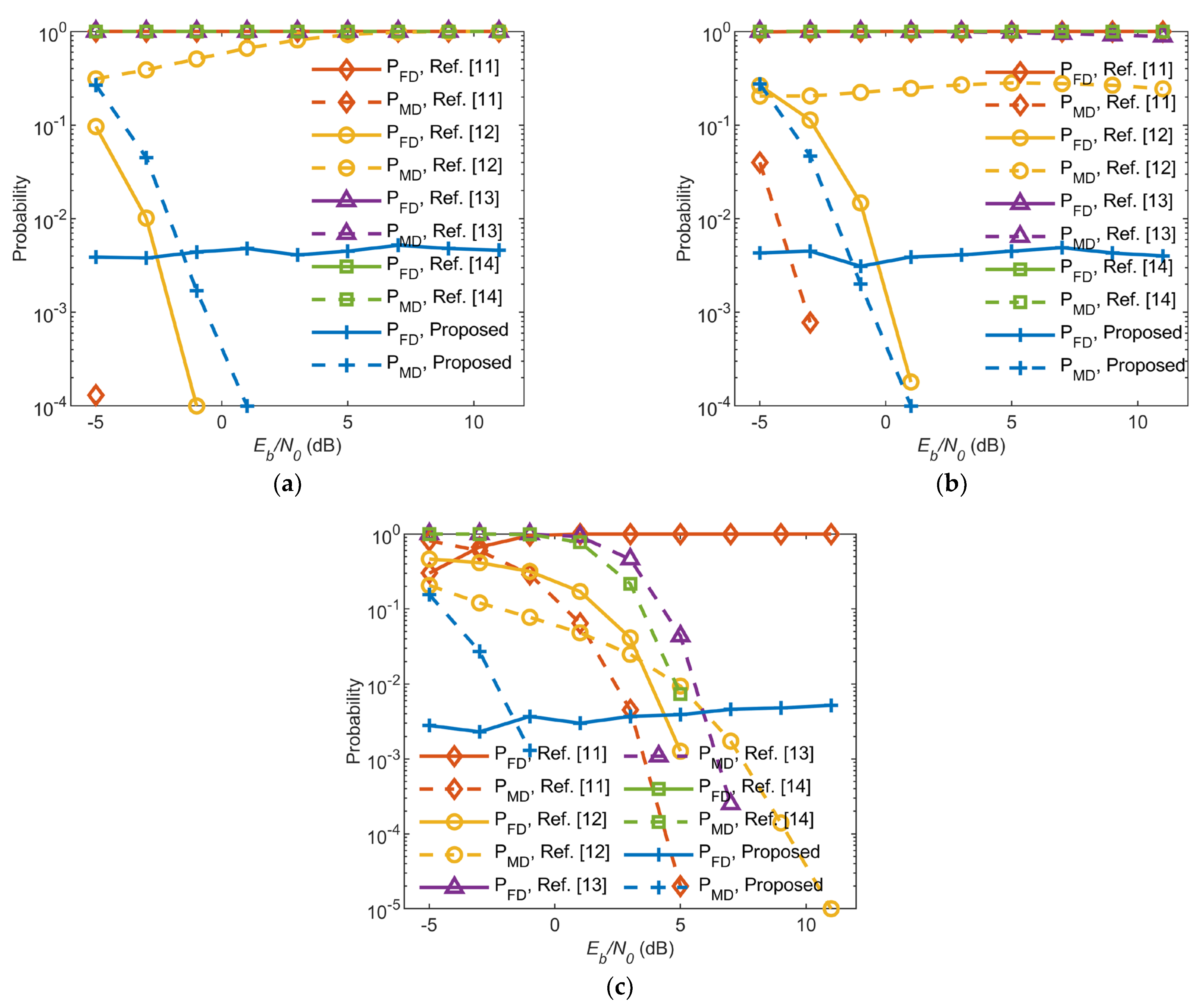
Figure 1. False detection probability and missed detection probability of the proposed method and published methods under different SIRs and Eb/N0s. (a) SIR = −10 dB, (b) SIR = −6 dB, (c) SIR = −2 dB. The false detection probabilities are plotted with solid lines, whereas the missed detection probabilities are plotted with dashed lines.
Remotesensing 16 03152 g001
Figure 2. MRE of CFO estimation under different SIRs and Eb/N0s. (a) SIR = −10 dB, (b) SIR = −6 dB, (c) SIR = −2 dB.
Remotesensing 16 03152 g002
Table 1. Simulation parameters.
ParameterVariableValue
Channel bandwidthB250 kHz
Symbol period T b 6.25 µs
Initial magnitude of signal c 0 1
Initial phase of the first symbol φ 0
The number of sampling points within a symbol N s 32
Sampling period T s T b / N s
The number of in-band interferencesM3
CFO Δ f 25.5 kHz
Disclaimer/Publisher’s Note: The statements, opinions and data contained in all publications are solely those of the individual author(s) and contributor(s) and not of MDPI and/or the editor(s). MDPI and/or the editor(s) disclaim responsibility for any injury to people or property resulting from any ideas, methods, instructions or products referred to in the content.