1. Introduction
With the rapid development of unmanned aerial vehicles (UAVs), unmanned ships (USVs), autonomous driving, and other technologies, there is a growing demand for high-precision real-time navigation. The Global Navigation Satellite System, as a mainstream means of navigation, has attracted much attention in the industry due to its global coverage, long-term effectiveness, and all-weather working capability. A GNSS, as a standard navigation sensor, is able to provide reliable positioning services in most situations. However, in complex environments such as urban canyons and tunnels, GNSS signals are susceptible to occlusion, leading to navigation interruptions [
1]. In addition, GNSS signals increase in noise when subjected to interference, which, in turn, affects navigation accuracy [
2,
3]. More importantly, GNSSs are unable to provide all of the navigation status information required for certain carrier control, such as precise horizontal attitude angles [
4]. Therefore, a single GNSS may have limitations in continuous navigation missions.
In order to overcome the shortcomings of a single sensor and improve the overall performance of the navigation system, it is necessary to introduce other sensors for assistance. Inertial Measurement Units (IMUs), consisting of gyroscopes and accelerometers, do not rely on external signals and offer higher autonomy, faster update rates, and more stable short-term accuracy. Although IMUs suffer from errors accumulated over time, their fusion with a GNSS can fully utilize their respective advantages and complement each other [
5]. The integrated system composed of a GNSS and an inertial navigation system (INS) is superior to single-element navigation systems in terms of stability and accuracy. With the advancement of GNSS receiver and Micro-Electro-Mechanical System (MEMS) technology, the cost of combined satellite–inertial navigation systems has been reduced significantly, which paves the way for their wide application in smart driving vehicles.
Currently, the combined navigation schemes based on the integration of a GNSS and an INS are mainly categorized into loosely coupled (LC), tightly coupled (TC), and deeply coupled (DC) forms based on the level and complexity of their combination [
6]. In the loosely coupled scheme, the GNSS and INS operate as two independent systems, with the GNSS being responsible for providing long-term corrections of position and velocity and the INS providing short-term, high-precision data. Due to its simple structure and redundancy, the LC scheme is currently the most widely adopted navigation scheme. However, the LC scheme suffers from the problem of serial filtering in data processing and cannot effectively utilize GNSS data to assist the INS for navigation when the number of visible satellites is less than four. Compared to the LC scheme, the deep-coupling scheme fuses GNSS and IMU data in the signal processing stage, and its distinctive feature is that it utilizes the velocity information of the INS to assist the tracking loop of the GNSS receiver, which enhances the receiver’s anti-jamming capability, improves the dynamic performance, and reduces the dynamic error. However, this scheme requires the high computational capability of the hardware and is difficult to realize, so it is mainly used in the military and aerospace fields. For civilian carriers, the performance and cost–benefit ratio of the DC scheme still need to be further evaluated. The TC scheme fuses GNSS and IMU data at the algorithmic level with high accuracy and robustness, and even when the satellite observation is poor, the TC combined system does not need the complete GNSS information to assist the INS, and fusion processing can be carried out when visible satellites are fewer than four [
7].
Although TC schemes are able to maintain combined navigation in environments where GNSS signals are obstructed, errors due to non-line-of-sight (NLOS) reception in such environments can be tens of meters or more, with multipath effects being particularly severe. Signal errors due to reflectors such as high-rise buildings or mountains may reach the kilometer level [
8]. In addition, TC schemes cannot provide effective corrections when the GNSS signal is completely blocked. Therefore, robust navigation schemes for environments with severe degradation in GNSS performance have become the focus of researchers’ attention. A common approach to solving such problems is to add additional sensors. For example, Chang et al. successfully improved the precision of navigation positioning by integrating 3D laser radar into the navigation system [
9]. The radar also reduces the drift of the inertial navigation system (INS) during long-term GNSS interruptions [
10,
11]. Wen et al. captured environmental scenes in urban canyons using fisheye cameras, matched them with satellite positions through calculation, and excluded invisible satellites, thus achieving better filtering performance [
12]. Zhong and NG addressed the limitations of the GNSS by employing 3D mapping techniques [
13,
14]. Wu and Jang, on the other hand, used Ultra-Wide-Band (UWB) technology to cope with the insufficient number of visible GNSS satellites [
15,
16]. Some studies have intended to mitigate the impact of degraded GNSS environments by combining information from additional sensors, such as cameras and laser scanners [
17,
18,
19,
20]. Although the aforementioned approaches can mitigate the impact of GNSS-restricted environments to some extent, the simple addition of sensors would significantly increase costs. Moreover, certain sensors require extensive preliminary work, such as pre-built high-definition maps, which are not feasible in new environments. Additionally, the introduction of additional sensors also increases the complexity of algorithms, making it challenging to meet the higher navigation output frequency requirements of some carriers. In this study, the vertical gyro (VG) algorithm is employed to assist the TC scheme in navigation. The VG algorithm determines the maneuvering state based on the accelerometer output. When the carrier is stationary, moving at a constant speed, or experiencing low acceleration, the VG measurements can correct the horizontal attitude, providing the carrier with a certain level of accurate horizontal attitude reference. Within a certain time frame, the VG algorithm effectively suppresses the divergence of navigation solution results [
21]. This algorithm does not require the addition of extra sensor equipment and does not impose a significant computational burden, thereby achieving the high-frequency output of navigation signals.
In addition, with the development of the multi-constellation multi-frequency GNSS, the measurement update of the TC integrated GNSS/INS can use the multi-satellite pseudo-range, the pseudo-range rate, Doppler velocity, and other types of observations. If all of the visible satellite observation data are input into the filter, high-dimensional observation vector processing will consume great arithmetic power, and embedded processors may not be able to achieve real-time navigation output. Therefore, to ensure the real-time capability of the navigation system, it is necessary to select a subset of the observed satellites from all visible satellites. However, the research on satellite screening algorithms has been mainly focused on finding the best Geometric Dilution Precision Factor, which is generally regarded as the amplification of the measurement error, while the positioning accuracy of satellite navigation is also related to the User Equivalent Range Error [
22]. In this paper, we present a weighted quasi-optimal satellite selection algorithm designed by considering other relevant terms that determine the accuracy of satellite navigation data and analyze the performance and efficiency of the method through comparison experiments with the optimal satellite selection algorithm. Our main contributions are (1) applying the VG algorithm to the TC integration scheme to give a new fusion scheme, (2) designing a new satellite selection algorithm by utilizing the correlation term that determines the User Equivalent Range Error while guaranteeing the real-time capability of the system and the accuracy of the observation data, (3) making a complete performance comparison of the navigation algorithm results with the LC and VG-free systems, as well as providing a comprehensive evaluation of the satellite selection algorithm.
This paper is organized as follows:
Section 2 outlines our combined navigation system model and algorithm.
Section 3 describes our given satellite selection algorithm.
Section 4 presents simulation experiments on our navigation model and satellite selection algorithm and evaluates the results. In the last section,
Section 5, the paper is summarized and discussed.
3. Satellite Selection Algorithm
Currently, the major global satellite navigation systems include the United States’ GPS, China’s BDS, Russia’s GLONASS, and Europe’s Galileo, making up the four major systems. With the development of multi-constellation and multi-frequency satellite navigation systems, integrated navigation systems can obtain more pseudo-range and pseudo-range rate observations during the measurement update period. If all observation signals are directly input into the filter without any screening, the correlation matrix will be large, leading to significant computational and memory consumption issues. Furthermore, incorrect observation inputs would cause deviations in the filtering results. Therefore, in order to achieve real-time and precise tightly integrated navigation results, it is necessary to both consider the number of satellite observation inputs and ensure the accuracy of the observations. This chapter provides a detailed introduction to the evaluation indicators of satellite positioning accuracy, as well as the satellite selection algorithm used in the integrated navigation system designed in this paper.
3.1. Geometric Dilution Precision
The Dilution of Precision (DOP) is an important physical quantity for measuring the satellite positioning accuracy, which is affected by the geometric structure of the satellites. The effect of the satellite geometric structure on the position error is also called the GDOP, which represents the ratio of the position error to the ranging error [
24], and is also an important evaluation index in the satellite selection algorithm. The relationship between the positioning accuracy of the satellite navigation system and the Geometric Dilution of Precision can be expressed by the formula
where
is the standard deviation of the navigation error, and
is the uncertainty error of the pseudo-distance measurement value, also known as User Equivalent Range Error (UERE). It can be seen that when
is certain, the GDOP is smaller, and the smaller the
is, the higher the navigation accuracy is. However, different positioning satellites’
values are generally not the same, and a smaller GDOP does not guarantee higher navigation and positioning accuracy. In certain situations, when a satellite cluster at a low elevation angle can provide a better geometric structure, it is more affected by the ionosphere and troposphere compared to satellites at high elevation angles. It also experiences stronger multipath interference [
5]. The uncertainty error of the pseudo-range measurement will be significantly larger than that of other satellites, and the positioning accuracy will be greatly affected at this time. Nevertheless, selecting a satellite combination with a smaller GDOP is still an important step to improve the integrated navigation accuracy.
The GDOP is defined in detail as
where
can be expressed in the form of the matrix
is the matrix associated with the satellite line-of-sight vector
is the line-of-sight vector from the receiver to satellite
i.
At an intuitive level, the structural relationship between the size of the GDOP value and the spatial distribution of the satellite constellation is shown in the following way: the larger the GDOP is, the more densely the satellites are distributed in space, and conversely, the smaller the GDOP is, the more dispersed the satellites are distributed in space. In the former case, the satellite positioning error is larger, so generally speaking, a dispersed layout can obtain better navigation results. The satellite selection algorithm is designed to select the combination of satellites that makes the GDOP stable and smaller within a shorter time.
3.2. Quasi-Optimal Satellite Selection Algorithm
The quasi-optimal satellite selection algorithm (QOSA) calculates the geometric redundancy of each satellite with other satellites through the spatial position information of the visible satellites. It then gradually removes the satellites with the largest redundancy and updates the sequence of visible satellites until the number of remaining satellites reaches the required minimum number [
25]. The core idea of the algorithm is to establish the satellite redundancy equation, quantify the redundancy, and approximate the optimal satellite combination with a small amount of computation. The redundancy between two satellites can be expressed as the following cost function:
where
is the angle between the line-of-sight vectors
and
of the two satellites
i and
j and the receiver. When the two satellites are co-linear with the receiver, i.e., when
is
or
, the cost function is maximum and the two satellites have the maximum redundancy, whereas when the line-of-sight vectors of the two satellites are perpendicular, i.e., when
is
, the cost function is minimum. In order to select the satellite with maximum redundancy from multiple satellites, the cost function of a single satellite with respect to all the satellites should be established. The cost function of a single satellite i can be expressed as
The process of the quasi-optimal satellite selection algorithm can be roughly described as follows: first, calculate the cost function for each satellite, and then eliminate the satellites with the largest cost function; if the number of satellites is larger than the desired value, repeat the process until the number of satellites reaches the selection requirement.
As explained at the end of the previous section, generally, the smaller the satellite navigation positioning error is, the smaller the GDOP value will be, and the more dispersed the satellite layout in space is. Due to the quasi-optimal satellite selection algorithm’s practice of eliminating satellites with maximum redundancy, the final satellite selection result will tend to disperse the satellite layout in space. Although this algorithm is similar to a greedy algorithm, each round of the satellite selection algorithm only considers the current optimal solution and cannot guarantee that the final result is the global optimal solution, but compared with the large amount of computation that the optimal satellite selection algorithm needs to calculate the GDOP
times [
26], the quasi-optimal satellite selection algorithm is more suitable for engineering applications.
3.3. Weighted Quasi-Optimal Satellite Selection Algorithm
Although the quasi-optimal satellite selection algorithm is close to the optimal selection algorithm and is more efficient, the satellite navigation system positioning accuracy is not only related to the GDOP but also affected by the uncertainty error of each pseudo-range measurement value, as shown in Equation (
17). Pseudo-range measurements are affected by atmospheric ionospheric and tropospheric delays, multipath effects, and orbital errors [
5]. The signal-to-noise ratio of the satellite signal will decrease with the increase in the noise of the measured value and increase with the increase in the satellite elevation angle, while the multipath effect and satellite orbit error will also reduce the signal-to-noise ratio. So, at the same time, considering the satellite elevation angle, signal-to-noise ratio, and multipath effect, a weighted quasi-optimal satellite selection algorithm (WQOSA) of the weight function can be constructed. This paper refers to the literature [
27] to give a weight function construction method:
where
and
are the elevation angle and signal-to-noise ratio of satellite i,
and
are the maximum elevation angle and the maximum signal-to-noise ratio of the visible satellites in the same calendar element, and
is the multipath scale factor. Under normal driving conditions, the multipath scale factor is usually set to 1, and when multipath effects are encountered, the multipath scale factor can be set to a value greater than 1. So, the multipath scale factor can be expressed as a function of the reflection coefficient
, which, in turn, is correlated with the carrier-to-noise density ratio (
) [
28]:
In the above equation,
is the carrier-to-noise ratio of satellite i, which indicates the strength of the received signal and is usually used to estimate the signal quality [
29], and it can be seen that when the carrier-to-noise ratio is larger,
is close to 1, which corresponds to a weaker satellite multipath effect.
Since the cost function of the QOSA has a value range from −1 to +1, to avoid the impact of positive and negative attributes on the weight function, it is also necessary to transform the cost function of the QOSA before constructing the cost function of the WQOSA. In this paper, we present the new cost function:
The cost function for a single satellite
i is then expressed as
The cost function for the WQOSA can then be constructed:
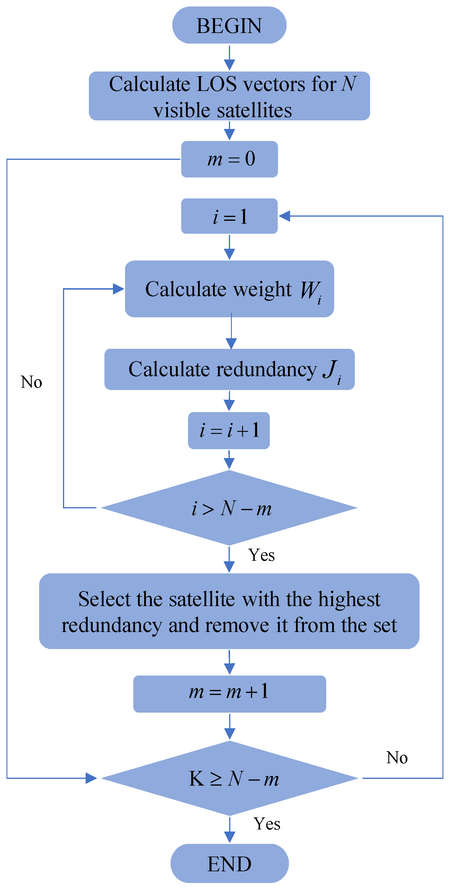
The satellite selection process of the WQOSA is similar to that of the QOSA, but it involves an additional weight calculation process. To provide a clearer illustration of the satellite selection process of the WQOSA, a flowchart of the algorithm execution is presented in
Figure 2.
4. Experiment and Analysis
As described in this section, we validated the performance of the proposed system through simulation experiments and tests based on a real-world sports car. For the integrated navigation algorithm, this paper will present two sets of comparative experimental results. In the first set of experiments, we compared our system with a Kalman filtering system using a loosely coupled algorithm. In the second set of comparative experiments, we demonstrated how our proposed algorithm enhances the robustness of the system in an environment where GNSS signals are limited. For the satellite selection algorithm, this paper will present the algorithm evaluation results and compare its computational efficiency with that of the optimal algorithm. Through these experiments, we can comprehensively assess the performance and efficiency of our proposed system in different application scenarios.
4.1. Equipment and Solutions
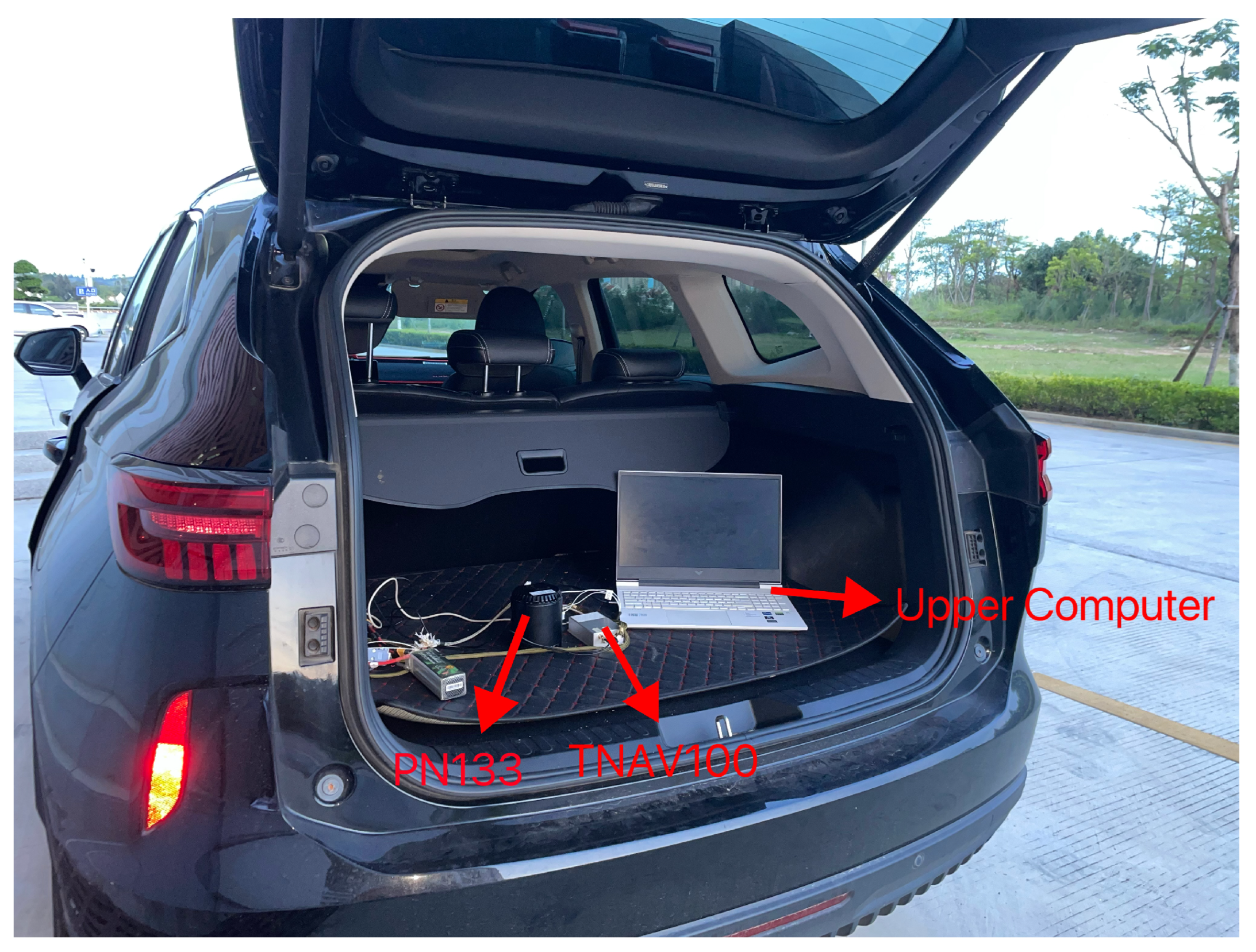
In this study, the inertial navigation components and computational equipment used in the experiments were all integrated within the TNAV100 flight control computer, which is a flight control and navigation system specifically designed for unmanned aerial vehicles. The system internally integrates key components, such as a three-axis gyroscope, a three-axis accelerometer, and a GNSS module. In particular, the IMU employs an ADIS16470 series MEMS-grade IMU, and the GNSS module is equipped with the UM982 receiver chip from UNICORECOMM company. Additionally, we set the data sampling frequencies for the IMU and the GNSS receiver to 200 Hz and 1 Hz, respectively. To ensure the precise comparison of error values in the experimental results, this experiment used a navigation system equipped with a high-precision fiber optic inertial navigation component, the PN133, as a reference. The output results of this system will serve as the benchmark reference values for navigation results based on MEMS inertial systems.
Figure 3 shows a photograph of the equipment used in this experiment.
Table 1 and
Table 2 detail the specific parameters of the inertial sensors of the experimental and reference systems for further technical comparison and analysis.
4.2. Performance Comparison: TC vs. LC
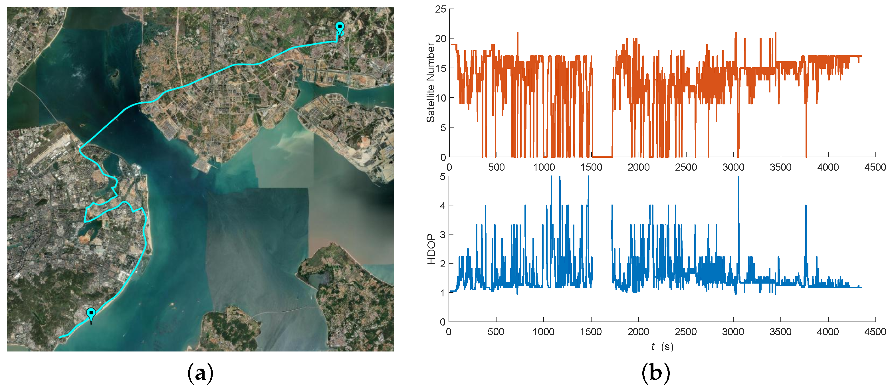
This experiment was conducted in the Xiamen area of China, during which the test vehicle traversed various special urban road sections, including urban overpasses, green belts, high-rise buildings, and underground tunnels. These road sections have a significant impact on the navigation system, and the collected data are thus representative of navigation in urban environments. The test vehicle passed through these sections at a regular driving speed, with vehicle operation maneuvers including stationary, acceleration, deceleration, and turning, reaching a maximum operating speed of nearly 120 km/h, and experimental data recording lasted for about 70 min.
During the experiment, the vehicle’s travel trajectory was meticulously recorded, as shown in
Figure 4a, which illustrates the changes in satellite visibility throughout the entire experimental process. When driving through special road sections, the satellite observation conditions became adverse due to obstruction by buildings and terrain, leading to significant fluctuations in the number of visible satellites. This phenomenon was meticulously recorded during the experiment and is presented in
Figure 4b in the form of a satellite count data graph, reflecting the challenges faced by satellite navigation systems in complex urban environments.
This study aims to delve into the dynamic characteristics of attitude, velocity, and position errors during the vehicle’s travel.
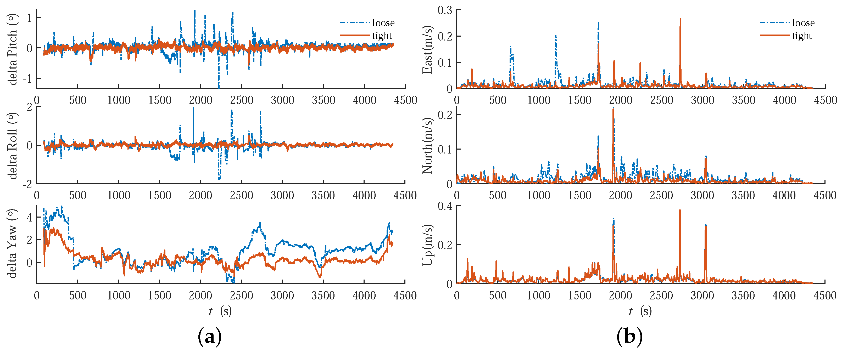
Figure 5a presents a data graph showing the performance of the loosely coupled (LC) and tightly coupled (TC) integrated navigation algorithms in terms of attitude angle errors in the horizontal and vertical directions. This graph reflects the performance differences between the two algorithms in maintaining the accuracy of vehicle attitude estimation.
Figure 5b provides statistics on the velocity errors of the LC and TC algorithms in the east, north, and vertical directions, demonstrating the specific impact of different coupling strategies on the accuracy of velocity estimation. Finally,
Figure 6 details the positional errors of the LC and TC algorithms in the three spatial dimensions of longitude, latitude, and altitude, showcasing the performance of the two algorithms in terms of positioning accuracy.
Figure 4b shows that there is a relatively long period of GNSS denial from 1500 s to 1700 s into the experiment. During this period, the navigation error results significantly increase. In addition to this, the experimental data also contain several short periods of GNSS denial. To effectively compare the performance of the LC scheme and the TC scheme proposed in this paper, we divide the experimental results into two parts: sections of the road with normal GNSS signals and the entire route, which includes the aforementioned long period of GNSS denial. These are presented and analyzed separately.
Table 3 summarizes the root mean square error (RMSE) of the two coupling schemes in terms of horizontal attitude, vertical attitude, velocity, and position estimation. This provides a quantitative basis for the assessment and a comparison of the performance of the two schemes.
From
Table 3, it can be seen that the experimental results for both types of road sections show that the TC scheme provided in this paper performs better than the LC scheme in terms of attitude, velocity, and position estimation accuracy. The specific improvements are as follows:
- (1)
For the GNSS normal road section experimental results, compared with LC, the TC scheme reduced the RMSE of the horizontal attitude from 0.210 degrees to 0.078 degrees, the RMSE of the vertical attitude from 1.59 degrees to 0.76 degrees, the RMSE of velocity from 0.032 m/s to 0.026 m/s, and the RMSE of position from 2.81 m to 2.00 m. These improvements correspond to approximately 62.68%, 52.20%, 18.75%, and 28.82% increases in accuracy, respectively.
- (2)
For the experimental results of the road section containing GNSS denial, the TC scheme also shows a significant improvement over the LC scheme. In terms of velocity and position estimation, the TC scheme achieved approximately 20.00% and 35.82% increases in accuracy compared to the LC scheme.
4.3. Performance Comparison: With VG vs. without VG
For the same dataset as in
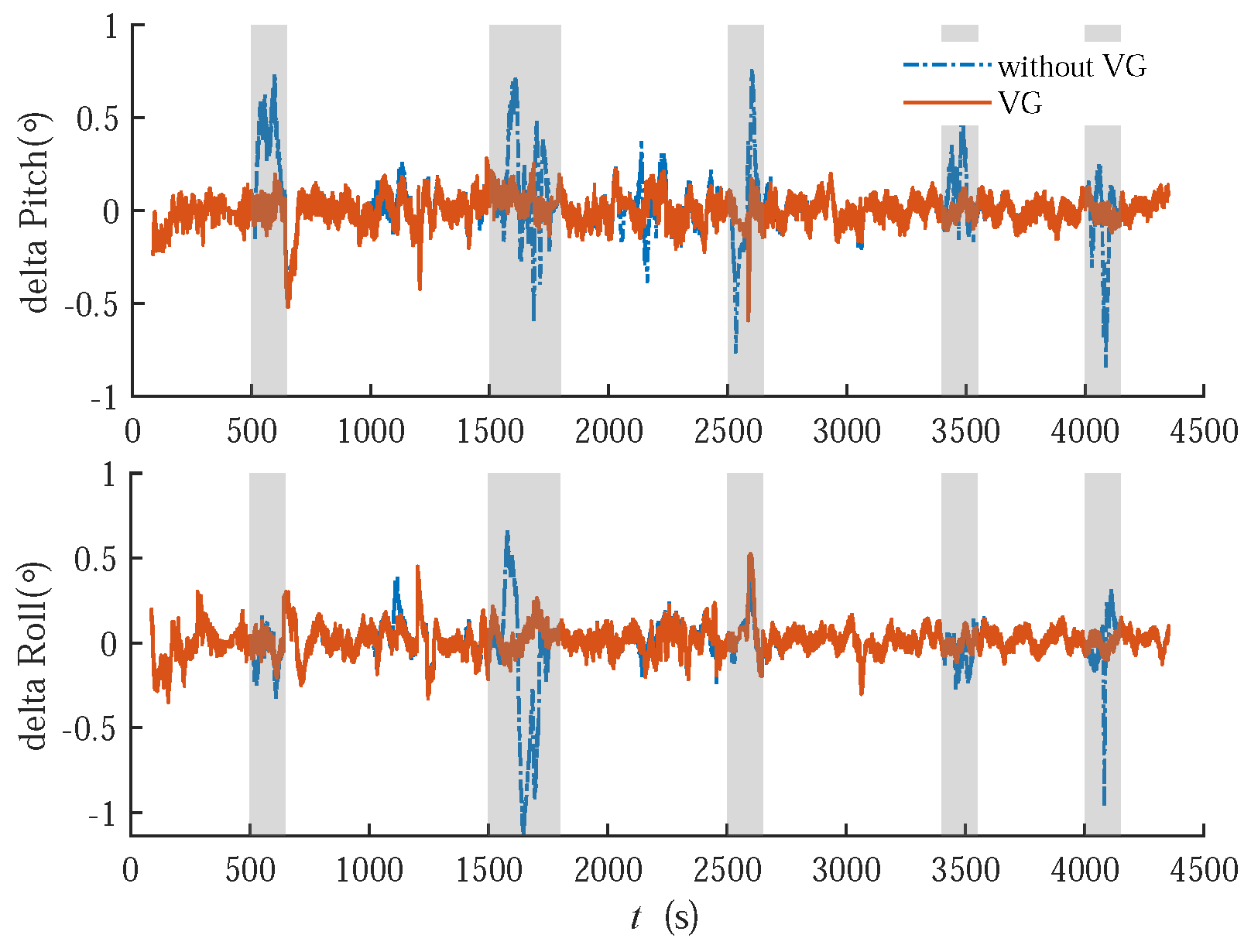
Section 4.2, this study verified the robustness of the VG pitch and roll observations on the attitude filtering results under GNSS denial conditions through simulation of the dataset. The error comparison charts shown in
Figure 7a–c, respectively, demonstrate the performance of the TC integrated navigation algorithm in terms of horizontal and vertical attitude angle errors, velocity errors, and position errors for this set of data with and without VG correction.
From the experimental attitude error in
Figure 7a, it can be clearly observed that during the long period of GNSS denial from 1500 s to 1700 s, the correction effect of the VG on the estimation of the horizontal attitude angle is quite significant, with the peak of the maximum error being significantly lower than that of the filtering scheme without VG correction. However, there is no significant improvement in the vertical attitude error, velocity error, or position error. To more accurately quantify the effect of VG correction,
Table 4 summarizes the RMSE of the two observation schemes in the estimation of the AVP (attitude, velocity, position).
Consistent with the analysis of various error result graphs,
Table 4 shows that the VG has a certain optimization effect on the AVP estimation accuracy of the carrier, with significant optimization in the horizontal attitude angle. Specifically, the VG scheme reduced the RMSE of the horizontal attitude from 0.108 degrees to 0.078 degrees, the RMSE of the vertical attitude from 0.80 degrees to 0.76 degrees, the RMSE of velocity from 0.031 m/s to 0.028 m/s, and the RMSE of position from 2.69 m to 2.39 m. These improvements correspond to approximately 27.78%, 5.00%, 9.68%, and 11.09% increases in accuracy, respectively.
Based on the aforementioned analysis, we have recognized the significant effect of the VG in optimizing the estimation of the horizontal attitude. Given that the improvement effects of the VG on the estimation of other state quantities are not obvious, this study will not delve further into these aspects. To further verify the optimizing effect of the VG on the estimation of the horizontal attitude angle and to examine its ability to suppress the divergence of the estimation in the carrier under conditions of weakened or denied GNSS signals, this study intentionally introduced periods where GNSS signals are unavailable to simulate extreme situations of GNSS signal denial and conduct a detailed analysis. To this end, we actively added four periods of GNSS signal denial to the experimental data, located at 500 to 600 s, 2500 to 2600 s, 3400 to 3500 s, and 4000 to 4100 s, each lasting for 100 s.
Figure 8 presents the horizontal attitude estimation results obtained through simulation during these specific periods.
The conclusion remains within our expectations:
Figure 8 shows that the VG has a positive optimizing effect on the estimation of the horizontal attitude angle during each long period of GNSS denial.
Table 5 summarizes the RMSE of attitude estimation for the two observation schemes in both the global time period and the period containing only GNSS denial. Specifically, during the global time period, the VG scheme reduced the RMSE of the horizontal attitude from 0.149 degrees to 0.081 degrees, and during the period containing only GNSS denial, it was reduced from 0.240 degrees to 0.098 degrees. The optimizations in these two types of periods correspond to improvements of 45.63% and 59.17%, respectively.
4.4. Satellite Selection Algorithm Results
To verify the greater capability of the weighted quasi-optimal satellite selection algorithm presented in this paper for engineering applications compared to the optimal satellite selection algorithm, this experiment compared the quality of satellite selection and performance between the two algorithms. The data used in this experiment were collected in an open area with satellite signals from the GPS and BDS systems.
Figure 9a shows the trajectory of the experimental carrier.
Figure 9b, on the other hand, displays the number of satellites and the GDOP values for all satellites during the experiment.
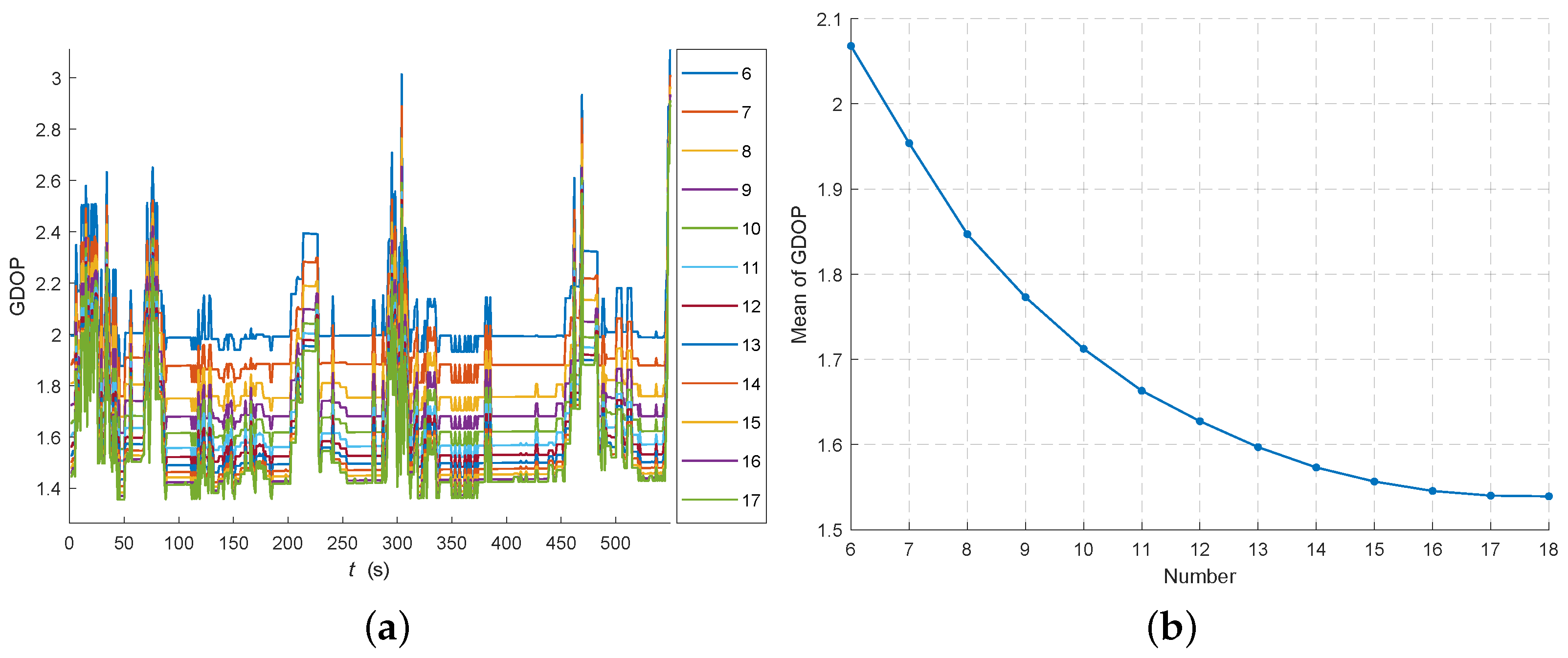
Before starting the comparative experiment, it was necessary to determine the number of satellites selected for our experiment. Although there are no strict requirements for the number of satellites selected, we need to follow a principle that, while ensuring the satellite navigation positioning accuracy meets requirements, the number of selected satellites should be as small as possible. The advantage of doing so lies in the fact that it can reduce the computational scale in the integrated navigation solution, thereby lowering computational complexity and minimizing the potential impact on the accuracy of error estimation. Our approach is to first use the optimal satellite selection algorithm to calculate the optimal GDOP values at various times for 6 to 17 satellites. Based on these calculations, we further plot the curve of the average GDOP values under different numbers of satellites. Through a detailed analysis of this curve, we can select the optimal number of satellites. In addition, according to the satellite count graph shown in
Figure 9b, we observe that the maximum number of visible satellites is 18. Therefore, when selecting the number of satellites, we limit the maximum number of considered satellites to 17.
The GDOP variation curve for the optimal satellite selection algorithm under various numbers of selected satellites is shown in
Figure 10a. It can be visually observed that as the number of selected satellites increases, the GDOP values at each moment do not decrease uniformly, but rather, the rate of decrease gradually slows down. To more clearly demonstrate this rate of decrease, the curve of the average best GDOP values for each number of selected satellites is displayed in
Figure 10b. The results show that when the number of selected satellites is between 6 and 8, the GDOP value changes by about 0.1; between 8 and 10, the change is around 0.06; and between 10 and 12, the change is close to 0.03. Beyond 12 satellites, this change drops to about 0.01. Therefore, in order to balance the reduction in the GDOP and keep the number of selected satellites as small as possible, we selected 12 satellites for the experiment.
After determining the number of selected satellites, we conducted simulation experiments for the optimal satellite selection algorithm (OSA), QOSA, and WQOSA. The results of the experiments are shown in
Figure 11a, which illustrates the GDOP variation curves. The figure demonstrates that the GDOP variation curves of the QOSA and WQOSA, after satellite selection, exhibit a similar trend to those obtained by the OSA. However, overall, the GDOP values of the WQOSA and QOSA are slightly higher than those of the OSA. The GDOP values of the WQOSA range from 1.5 to 2.5, with occasional values close to 3, but they still fall within the range of excellent positioning accuracy. Through calculations, we obtained average GDOP values of approximately 1.628 for the OSA, 1.785 for the QOSA, and 1.809 for the WQOSA. We also analyzed the differences among the three methods and plotted two GDOP difference curves. From these curves, it can be observed that the difference between the WQOSA and OSA fluctuates between 0 and 0.5, with an average difference of approximately 0.1815. The average difference between the QOSA and WQOSA is 0.0424. Although the WQOA’s GDOP is slightly higher than that of the QOSA, the difference is relatively small.
The above analysis shows that the difference in satellite selection results between the WQOSA and OSA is very small, and the quality of satellite selection is very close. To further evaluate the performance of the two, we also compared the time consumption during the execution process. We analyzed the running times of the two algorithms within each time element and plotted the running time comparison chart between the OSA and WQOSA, as shown in
Figure 11b. From the chart, it can be clearly observed that there is a significant difference in the order of magnitude of time consumption between the two algorithms. After calculation, we found that the average running time of the OSA is 0.1057 s, while the average running time of the WQOSA is only 0.0002723 s, which is about a 388 times difference. Considering the 200 Hz sampling frequency of the IMU, our system must complete one round of correction calculation within 5 ms to meet real-time requirements. Obviously, the running time of the OSA is far beyond this limit. On the contrary, the running time of the WQOSA, which is 0.27 ms, not only is far below the threshold of 5 ms but also meets this condition even in the worst case in this set of data. Therefore, the WQOSA not only has comparable satellite selection quality to the OSA but also has a clear advantage in running time, which can fully meet our requirements for high-performance integrated navigation systems.
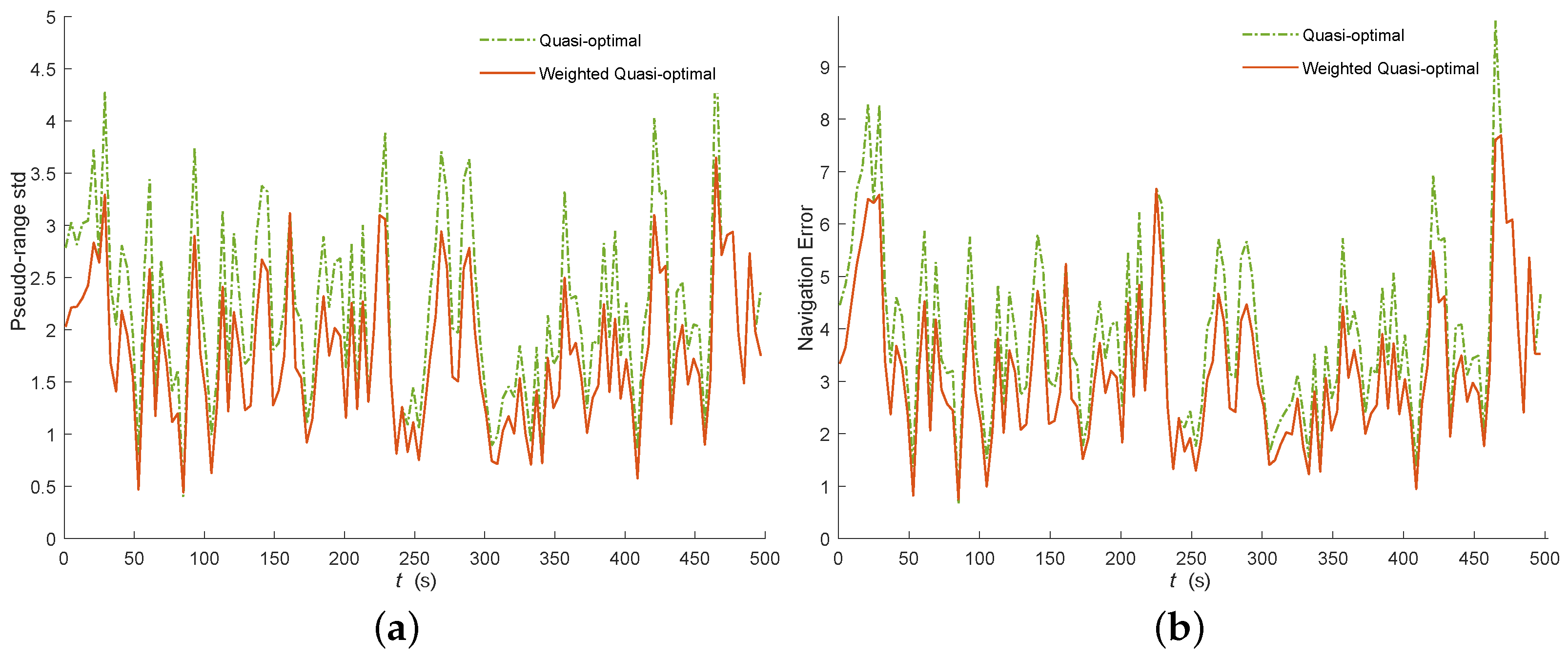
To verify the improvement of the WQOSA over the QOSA in satellite selection quality, we conducted a comparative experiment between the two algorithms. Following Equation (
17), we used the standard deviation of pseudo-range measurement errors as a substitute for UERE [
30] and analyzed the average pseudo-range error standard deviation of the satellite selection results for both algorithms. A comparison graph, as shown in
Figure 12a, was plotted accordingly. The results in
Table 6 show that the WQOSA outperforms the QOSA in this metric, with specific average values of 1.787 (WQOSA) and 2.237 (QOSA). This aligns with our expectations, as the WQOSA considers additional influencing factors beyond the satellite distribution during the satellite selection process.
Finally, we comprehensively evaluated the satellite selection quality of both algorithms by considering both the GDOP and UERE. The average pseudo-range error standard deviation at each time point was multiplied by the GDOP, and the results are shown in
Figure 12b. This yielded the navigation error standard deviation curves for both algorithms. It is evident that in certain time intervals, the satellites selected by both algorithms completely overlap, resulting in consistent curves during that period. However, for the majority of the time, the WQOSA exhibits a significantly smaller error standard deviation compared to the QOSA. Specifically, the average values of the two curves are 3.241 (WQOSA) and 3.941 (QOSA). In conclusion, the WQOSA demonstrates superior satellite selection quality over the QOSA.
5. Discussion
The simulation experiments carried out in this study comprehensively evaluate the proposed tightly coupled GNSS/INS navigation system, focusing on the accuracy, robustness, and computational efficiency of the system. Our results demonstrate several key findings.
Firstly, the proposed combined navigation scheme shows a significant improvement in state estimation accuracy compared to the LC navigation system. Even in environments with poor satellite observation conditions, the TC system provides a reliable attitude estimation. This robustness is attributed to the multi-source data fusion, which includes the pseudo-range, pseudo-range rate, and dual-antenna observation from the GNSS and the horizontal attitude angle from the VG. The VG algorithm is particularly effective in correcting horizontal attitude errors during periods of GNSS signal degradation, thereby enhancing the overall stability of the navigation solution. Secondly, the weighted quasi-optimal satellite selection algorithm proposed in this paper effectively reduces the computational burden of the navigation system without compromising the accuracy of the observation data. By selectively screening observable satellites, the algorithm maintains high computational efficiency, which is crucial for real-time navigation applications. The comparison experiments with the OSA and QOSA highlight the advantages of our method in terms of both computational efficiency and engineering practicability.
The performance of the TC system under non-line-of-sight (NLOS) conditions and multipath effects also warrants discussion. Although the TC scheme maintains navigation functionality in such environments, errors introduced by NLOS reception and multipath can still be significant. Future work could explore the incorporation of advanced multipath mitigation techniques or the integration of additional complementary sensors to further enhance system performance.
In terms of practical applications, the reduced computational load and improved accuracy make the proposed system highly suitable for smart driving vehicles and other civilian carriers where cost and real-time performance are critical factors. The integration of the VG algorithm and the weighted quasi-optimal satellite selection algorithm presents a balanced approach that addresses both the accuracy and efficiency requirements of modern navigation systems.
In conclusion, the proposed tightly coupled GNSS/INS navigation system with multi-source data fusion and an optimized satellite selection algorithm demonstrates significant improvements in navigation accuracy, robustness, and computational efficiency. These results support the feasibility of deploying such systems in real-world applications where high precision and reliability are essential.
