Abstract
Scatterometers are highlighted in polar applications, such as sea ice extent retrieval. There are currently three types of spaceborne scatterometer in operation, among which the rotating pencil beam scatterometer and the rotating fan beam scatterometer have similar rotating observation geometry, but different beam sampling. However, it is difficult to objectively evaluate the performance of the two rotating beam scatterometers using the obtained data. This is because there are significant differences in their system parameters, which in turn affects the objectivity of the evaluation. Considering the high flexibility of the rotating fan beam scatterometer, this study proposes a dual-mode sea ice extent retrieval method for the rotating fan beam scatterometer. The dual modes refer to the rotating fan beam mode (or full incidence mode) and the equivalent rotating pencil beam mode (or single incidence mode). The two modes share the same system and spatiotemporal synchronous backscatter measurements provide the possibility of objectively comparing the rotating pencil beam and rotating fan beam scatterometers. The comparison, validation, and evaluation of the dual-mode sea ice extent of China France Oceanography Satellite Scatterometer (CSCAT) were performed. The results indicate that the sea ice extent retrieval of the equivalent rotating pencil beam mode of the rotating fan beam scatterometer is realizable, and compared to the existing rotating pencil beam scatterometers (such as the OceanSat Scatterometer on ScatSat-1, OSCAT, on ScatSat-1, and the Hai Yang 2B Scatterometer, HSCAT-B), the derived sea ice extent is closer to that of Advanced Microwave Scanning Radiometer 2 (AMSR2). For the two modes of CSCAT, when compared to AMSR2, the sea ice extent of the CSCAT full incidence mode has smaller values of root mean squared error (RMSE), error-of-ice (EI), and ice edge location distance (LD) than those of the CSCAT single incidence mode. These suggest that the rotating fan beam scatterometer shows better observation abilities for sea ice extent than the rotating pencil beam scatterometers.
1. Introduction
Polar regions play an important role in regulating global climate conditions. Sea ice covers most polar regions, and its high albedo helps keep the polar areas cool. Therefore, sea ice extent is considered a sensitive indicator of long-term climate change on a global scale [1,2]. Because the remote sensing allows for instantaneous coverage of huge areas, polar-orbiting satellite data are useful for tracking and analyzing the fluctuations of the sea ice extent [3]. Data from active and passive sensors, such as microwave scatterometers and radiometers, have been used to estimate the sea ice extent [4]. The scatterometer has high operating frequency, high temporal and spatial resolution, and diverse observation geometry. Due to these unique characteristics, the scatterometer is highlighted in polar applications [5].
Since the first scatterometer launched in 1978, many scatterometer missions have been designed and launched [6]. In these missions, according to the different observation geometries, three types of spaceborne scatterometers have appeared successively, including fixed fan beam scatterometers (i.e., NASA Scatterometer, NSCAT; European Remote Sensing 1 and 2, ERS 1/2; Advance Scatterometer series, ASCAT-A/B/C), rotating pencil beam scatterometers (i.e., Seawinds/QuikSCAT; RapidSCAT; the OceanSat Scatterometer on OceanSat-2, ScatSat-1, and OceanSat-3, OSCAT; the Hai Yang 2 Scatterometer series, HSCAT-A/B/C/D), and rotating fan beam scatterometers (i.e., China France Oceanography Satellite Scatterometer, CSCAT; Wind Radar on FY 3E, WindRAD) [3]. The fixed fan beam scatterometer has a narrow and discontinuous swath, so its coverage rate is the lowest. The other two rotating beam scatterometers share the similar rotating observation geometry, but have different beam sampling. Figure 1 shows the observation geometries under the two rotating beam mechanisms. Note that the rotating fan beam scatterometer results in considerably more flexible observations at multiple incidences ranging from 20° to 60°, whereas the rotating pencil beam one is generally limited by one or two incidences. In addition, the rotating fan beam scatterometer features a smaller antenna size, a lighter weight, and narrower beam in the azimuth direction (about 1/3 times) than that of the rotating pencil beam scatterometer [7,8]. Table 1 provides a comprehensive comparison of the two kinds of rotating beam scatterometer. However, based on the obtained data, it is difficult to objectively evaluate the performance of these two rotating beam scatterometers. This is due to significant differences in their system parameters.
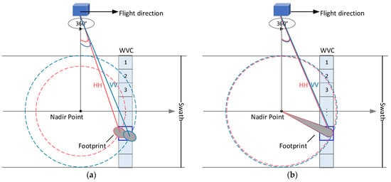
Figure 1.
Scan geometry of the rotating beam scatterometer: (a) pencil beam; (b) fan beam.

Table 1.
Comparison of the two types of spaceborne rotating beam scatterometer.
As a combination of the fan beam and rotating pencil beam scatterometer, the rotating fan beam scatterometer has a higher flexibility, and an equivalent rotating pencil beam observation mode can be obtained. That is, through some appropriate data preprocessing, the equivalent rotating pencil beam observation mode can be achieved from the rotating fan beam scatterometer data. The equivalent rotating pencil beam mode and the rotating fan beam mode form a dual observation mode. Note that the dual modes operate on the same system, achieving spatiotemporal synchronous observation of the Earth’s surface. This provides a possibility to compare the two types of rotating beam scatterometer more objectively. The rotating fan beam scatterometer (CSCAT and WindRAD) data have been proven to be useful for distinguishing sea ice from open ocean [9,10,11,12,13], and discriminating between first-year and multi-year ice [14,15,16,17]. Previous studies have shown that the Bayesian sea ice detection algorithm can be applied for both of the rotating beam scatterometers to retrieve the sea ice extent in polar regions [10,12,13,18,19]. However, there is little intercomparison of the sea ice extent retrieval performance between the two types of rotating beam scatterometer because of their different system parameters. Therefore, this study investigated the dual-mode sea ice extent retrieval for the rotating fan beam scatterometer. The dual modes refer to the rotating fan beam mode and the equivalent rotating pencil beam mode.
The major aims of this study were to (1) explore the feasibility of the equivalent rotating pencil beam mode of the rotating fan beam scatterometer on the sea ice extent retrieve in the Arctic and Antarctic regions; (2) analyze the performance of the equivalent pencil beam mode of the rotating fan beam scatterometer by comparing it with the existing rotating pencil beam scatterometers (such as OSCAT, HSCAT); and (3) objectively evaluate the two different types of rotating beam scatterometer by quantitatively comparing the dual-mode results of the rotating fan beam scatterometer. As such, this paper not only presents the realization and validation of the equivalent rotating pencil beam mode of the rotating fan beam scatterometer, but also discusses the different characteristics of the two beam types of the rotating beam scatterometer on the basis of the same system and consistent spatiotemporal data. Our purpose was to objectively explore the potential of multiple incidence data of the rotating fan beam scatterometer from the perspective of the sea ice extent retrieval.
Section 2 investigates the sea ice extent retrieval of the equivalent rotating pencil beam mode of the rotating fan beam scatterometer, including data preprocessing and algorithm parameter settings. Section 3 details the dual-mode sea ice extent retrieval process of the rotating fan beam scatterometer. Section 4 presents the comparison, validation, and evaluation of the dual-mode sea ice extent of CSCAT. Section 5 summarizes our results.
2. The Equivalent Rotating Pencil Beam Mode
Taking the CSCAT data as the primary data, the dual-mode sea ice extent retrieval of the rotating fan beam scatterometer is investigated in the paper. As the rotating fan beam mode of CSCAT has been elaborated in [12], this section focuses on the sea ice extent retrieval of the equivalent rotating pencil beam mode of CSCAT, including data preprocessing and Bayesian algorithm parameter settings.
2.1. Data Preprocessing
As shown in Figure 2a, CSCAT provides a sequence of 2–16 backscatter views per Wind Vector Cell (WVC). That is to say, there are 1–8 backscatter pairs for each WVC, and each backscatter pair includes both horizontal polarization (HH) and vertical polarization (VV). However, for the rotating pencil beam scatterometer, four backscatter observations per WVC are used for the sea ice detection [18]. These four observations are divided into two groups, namely fore plane and after plane. Observations on the fore/after plane have a similar antenna azimuth angle but different polarization. The antenna azimuth angle between the fore and after planes depends on the position of the WVC. Due to the similar incidence of HH and VV measurements in CSCAT, the four backscatter observations (or two pairs) with similar incidence can be extracted from the CSCAT data. To clarify the data extraction strategy, we first investigate the characteristics of the incidence and antenna azimuth angle of each WVC for CSCAT.
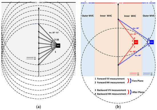
Figure 2.
Top view of CSCAT observation geometry: (a) rotating fan beam mode; (b) equivalent rotating pencil beam mode.
Figure 3 shows an example of the incidence and antenna azimuth angle of different WVC values for the 12th revolution of CSCAT data on 1 January 2019. Since the backscatter measurements in VV and HH polarization share similar incidences and antenna azimuth angles, only the results corresponding to the VV polarization are shown in the figure. Additionally, the WVC is numbered in order from the leftmost to the rightmost swath. Due to the symmetry of the incidence and antenna azimuth angles corresponding to WVC 1–21 and WVC 22–42, only the results of WVC 1–22 are shown in the figure. It can be seen that for WVC 1–4, each WVC can obtain a set of observation data, including symmetric forward and backward measurements when the incidence approaches 48°. For WVC 5–21, a set of forward and backward measurements at an incidence of nearly 40° can be obtained. Thus, four backscatters (or two pairs) with incidence of 40° or 48° can be extracted from the CSCAT L2A data, excluding each pair of backscatters when their antenna azimuth angle deviation is greater than 20°. In this way, for the inner WVC (i.e., WVC 5–38), the four backscatters with an incidence of approximately 40° are extracted, while for the outer WVC (i.e., WVC 1–4 and WVC 39–42), the four backscatters with an incidence close to 48° are extracted. The extracted four backscatters for each WVC form an equivalent rotating pencil beam mode of CSCAT, as shown in Figure 2b.
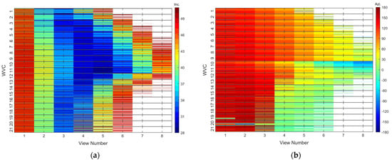
Figure 3.
The incidence and antenna azimuth angle for different CSCAT WVC values on 1 January 2019 (Revolution 12): (a) incidence; (b) antenna azimuth angle.
Using the same data as in Figure 3, the average incidences for each HH and VV polarized backscatter data in the fore/after plane are calculated, and the corresponding probability distribution is shown in Figure 4a. Note that for the inner WVC, the average incidences are around 38°–42°, most of which are concentrated at 40°. The average incidences of the outer WVC are about 48°. In addition, Figure 4b shows the distribution of antenna azimuth angles corresponding to the backscatter data in the fore/after plane. Observe that the antenna azimuth angles of the VV and HH polarized backscatter data are similar. The results suggest that the four backscatters of the equivalent rotating pencil beam mode of CSCAT can be extracted from the CSCAT data, demonstrating the feasibility of using the CSCAT equivalent rotating pencil beam to retrieve sea ice extent.
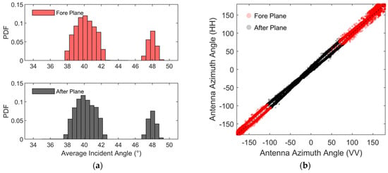
Figure 4.
The extracted data in the fore/after plane on 1 January 2019 (Revolution 12): (a) probability distribution of the average incidences; (b) distribution of the antenna azimuth angles.
Furthermore, the backscattering of the sea ice and open water from the equivalent rotating pencil beam mode data of CSCAT is shown in Figure 5. The distributions of VV backscatters and HH backscatters in both the fore plane and after plane for inner and outer WVCs are presented. It is evident that the backscatters of the sea ice are distributed along a symmetry line and conform to the one-dimensional line model, as in [18]. The backscatters of open water in two-dimensional measurement space deviate from the symmetry line in a fan-shaped distribution. The reason for this is that the backscatter of the open water is azimuth (and WVC) variant and polarization anisotropic (). The significant differences in the backscattering characteristics between them contribute to the sea ice extent retrieval for the CSCAT equivalent rotating pencil beam mode.
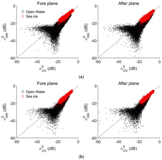
Figure 5.
The backscattering of sea ice and open water of the CSCAT equivalent rotating pencil beam mode data in the Arctic region on 15 March 2019: (a) inner WVC (40°); (b) outer WVC (48°).
2.2. Algorithm Parameters
The Bayesian algorithm for the sea ice detection of the rotating pencil beam scatterometer was proposed and applied for QuikSCAT Seawinds, OSCAT, and HSCAT [18,20,21]. For the equivalent rotating pencil beam mode of CSCAT, the sea ice detection algorithm follows a similar scheme. To avoid redundancy, this section only lists the main algorithm parameter settings, including Geophysical Model Functions (GMFs) and Maximum Likelihood Estimators (MLEs) for ocean wind and sea ice.
2.2.1. GMFs
GMFs are empirically derived functions that relate backscatter measurements to the surface conditions. The ocean wind GMF is an empirically derived model used to derive ocean surface wind vectors. NSCAT-4 has been used for CSCAT [7]. For the equivalent rotating pencil beam mode of CSCAT, NSCAT-4 is also utilized to calculate the required cone distance in the algorithm. In addition, the empirical sea ice GMF (or ice line), , can be derived from the stable winter backscatter of sea ice, as in [12,18,22,23].
Figure 6 shows the distribution of slope and intercept values obtained from the preprocessed Arctic daily backscatter data from January to March in 2019–2022. It is worth noting that for the inner or outer WVC, the ice lines obtained from the fore and after planes are basically the same, and the ice line parameters in the winter are very stable. In 2019, the ice lines corresponding to the inner WVC overlap along the symmetry line, and the slopes of the ice lines of the outer WVC are greater than those of the inner WVC, but the intercepts are all zeros. In 2020, there are significant differences in the slope and intercept of the ice lines for inner and outer WVCs. In 2021 and 2022, the ice line parameters for both the inner and outer WVCs are basically the same. Compared to the other three years, the values of the ice line parameters in 2021 are the lowest, which is related to the calibration issue of CSCAT in 2021.
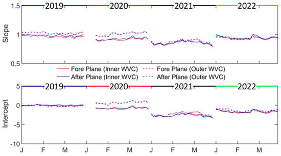
Figure 6.
Distribution of slope and intercept values derived from preprocessed Arctic daily backscatter data from January to March in 2019–2022.
In order to achieve a unified sea ice GMF, we first average the winter slope and intercept parameters for the fore plane and after plane. As the obtained slope/intercept of the fore and after planes are very close, we then average of the slope and intercept of the fore and after planes. Figure 7 shows the resulting ice lines and their specific parameter settings. It is found that there are certain differences in the sea ice GMF corresponding to the inner and outer WVCs in the same year. In addition, for the either inner or outer WVCs, the sea ice GMF obtained in different years also varies.
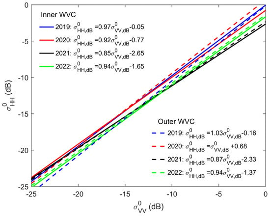
Figure 7.
Sea ice GMF for the equivalent rotating pencil beam mode of CSCAT.
2.2.2. MLEs
According to the backscatter space defined in [12], the extracted four backscatters for each WVC can be divide into two backscatter space (i.e., the fore plane and the after planes). In this way, the MLE of ice can be written as . Here i = 1, 2 correspond to the fore and after planes, and is the distance between the measured backscatter and the sea ice GMF. Figure 8 shows an example of the distribution of the distance for the inner and outer WVCs on the fore/after planes using the preprocessed CSCAT data on 15 March 2019. Note that the probability distribution of the distance between the measured backscatter and the sea ice GMF follows a Gaussian function, and the Gaussian parameters (mean μ and standard deviation std) are different for the inner WVC and outer WVC. In addition, for the inner WVC or outer WVC, there are differences in Gaussian parameters between the Arctic and Antarctic regions.
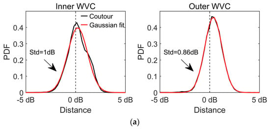
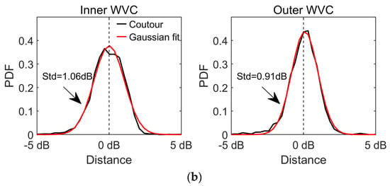
Figure 8.
Distribution of the distance between measured backscatter and the sea ice GMF model for the inner and outer WVCs on the fore/after backscatter plane using the preprocessed CSCAT data on 15 March 2019: (a) Arctic Region; (b) Antarctic Region.
In order to facilitate the distance normalization, it is necessary to obtain a unified Gaussian parameter. Therefore, we first investigate the characteristics of μ and std, and the results are shown in Figure 9. It can be seen that for the Arctic and Antarctic regions, the μ values obtained from the inner and outer WVC data are very close, and there is some fluctuation of the values at different months of the year, especially in 2020. However, there are significant differences in the std value of the inner and outer WVC. In addition, the μ or std values corresponding to the Arctic and Antarctic regions are similar. In order to facilitate the algorithm execution, we first average the μ and std of the Arctic and Antarctic regions every three months, and then use the average of these values as the final Gaussian parameters to normalize the distance. The results are shown in Figure 10. It is apparent that for different years, the μ values of the inner and outer WVCs are similar for the first three months (January to March), while there are significant differences in other months. For the inner WVC, except for 2019 (about 1.0 dB), the std value is approximately 1.5 dB; for the outer WVC, the std values are around 1.0 dB.
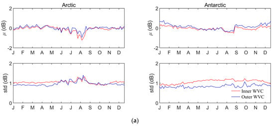
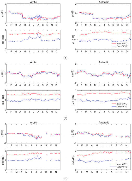
Figure 9.
The value of μ and std for the inner and outer WVCs in the Arctic and Antarctic regions using the preprocessed CSCAT data: (a) 2019; (b) 2020; (c) 2021; (d) 2022.
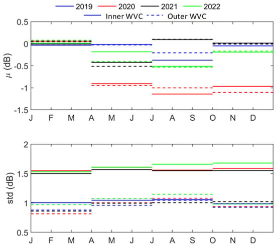
Figure 10.
Gaussian parameters for the distance normalization.
Based on the obtained Gaussian parameters, the distance between the measured backscatter and ice line model in the fore and after planes can be normalized, and the sum of the two distance squares follows a chi square distribution with two degrees of freedom. Figure 11 provides an example of the probability distribution of MLEice obtained from the preprocessed CSCAT data on 24 April 2020. Note that the observed MLEice distributions basically follow the expected chi square functions.
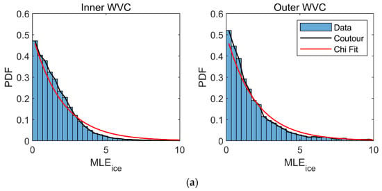
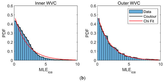
Figure 11.
The probability distribution of MLEice of the preprocessed CSCAT data on 24 April 2020: (a) Arctic region; (b) Antarctic region.
Based on the same preprocessed CSCAT data, MLEwind is calculated using the measured backscatters and NSCAT-4 model, and its probability distribution is given in Figure 12. We notice that the probability distribution of MLEwind follows a chi square distribution with two degrees of freedom, similar to [18].
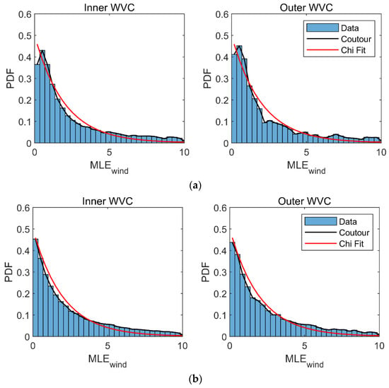
Figure 12.
The probability distribution of MLEwind of the preprocessed CSCAT data on 24 April 2020: (a) Arctic region; (b) Antarctic region.
3. Dual-Mode Sea Ice Extent Retrieval Process
In Section 2, we provide a detailed description of the sea ice extent retrieval for the equivalent rotating pencil beam mode of the rotating fan beam scatterometer. On this basis, the procedure for the dual-mode sea ice extent retrieval of the rotating fan beam scatterometer is described in this section. The flowchart for the process is shown in Figure 13. In this figure, the single incidence mode refers to the equivalent rotating pencil beam mode due to the fact that only CSCAT data with an incidence of 40° or 48° are utilized in this mode. Thus, the full incidence mode refers to the rotating fan beam mode.
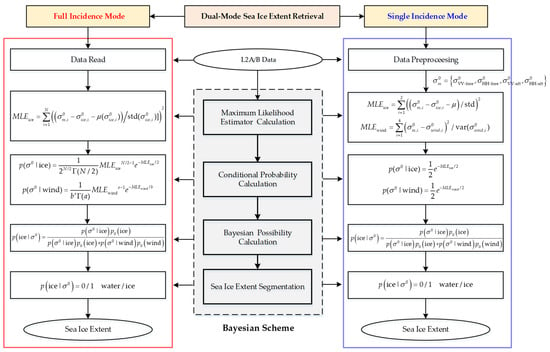
Figure 13.
Flowchart of the dual-mode sea ice extent retrieval for the rotating fan beam scatterometer.
The dual-mode sea ice extent retrieval follows a Bayesian scheme, as shown in the dashed box in the middle of Figure 13. The Bayesian scheme sequentially completes the maximum likelihood estimator (MLE) calculation, conditional probability and calculation, Bayesian probability calculation, and sea ice extent segmentation. The formulas of the Bayesian algorithms for the full incidence mode and single incidence mode are represented by the solid red and blue boxes accordingly. Note that these dual modes share the same Bayesian probability calculation and sea ice extent segmentation. The formula of is shown in the figure. For the sea ice extent segmentation, a threshold of 55% is set on , and then is obtained, where 0 denotes open water and 1 denotes sea ice.
The main differences between these two modes include the input data reading, MLE calculation, and and calculation. In the full incidence mode, the L2A/B data of the rotating fan beam scatterometer are read first. In the single incidence mode, the input L2A/B data are first preprocessed, that is, the four backscatter data with similar incidence of 40° or 48° are extracted from the input data. The extraction strategy is explained in Section 2.1. In addition, due to the different views of backscatter data applied in the two modes, there are also differences in the MLE calculation. In the full incidence mode, all views in each WVC are utilized, and the number of views N is different for each WVC. As shown in the figure, the MLE formula for ice is , which includes the parameters of the sea ice GMF, μ and std, as detailed in [12]. The MLE for wind, MLEwind, is obtained from the input L2B data. In the single incidence mode, the four views extracted from each WVC are used to calculate the MLEice and MLEwind. The corresponding formulas are shown in the figure. The parameters in the formulas are explained in Section 2.2. Based on the calculated MLE, the expressions of and for the dual modes are given in the figure. follows a chi square distribution with N/2 degrees of freedom. For the single incidence mode, N is 4, while for the full incidence mode, N varies. For the full incidence mode, follows a gamma distribution with parameter a and b, and the parameter values are presented in [12]. Meanwhile, follows a chi square distribution, and the degree of freedom is 2, as derived in Section 2.2.
4. Results and Discussion
In this section, we perform the comparison, validation, and evaluation of the dual-mode sea ice extent obtained from the rotating fan beam scatterometer. Firstly, the Bayesian probability images and sea ice extent images obtained from CSCAT dual modes are investigated. Then, the sea ice extent of the CSCAT dual modes, OSCAT on ScatSat-1, HSCAT-B, and the Advanced Microwave Scanning Radiometer 2 (AMSR2) are compared with each other for verification. Finally, a quantitative evaluation is conducted on the dual-mode sea ice extent of CSCAT.
4.1. Dual-Mode Sea Ice Extent
Based on the dual-mode sea ice extent retrieval process described in Section 3, the Bayesian probability images and sea ice extent images are obtained daily for CSCAT. Among them, a 55% threshold is used to segment sea ice extent images from the Bayesian probability images. Figure 14 shows an example of the Arctic Bayesian probability images and sea ice extent images obtained from the CSCAT dual-mode sea ice extent retrieval process. Note that there is a certain difference in the Bayesian probability distributions obtained by the two modes of CSCAT. Specifically, the probability values of the CSCAT full incidence mode are lower those that of the CSCAT single incidence mode in some open water regions. The corresponding sea ice extent from the CSCAT full incidence mode is about 11.07 million km2 while that from the CSCAT single incidence mode is 11.18 million km2.
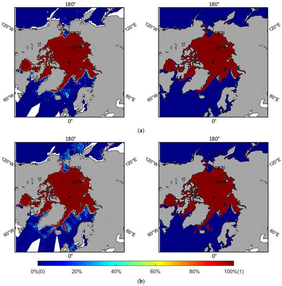
Figure 14.
Arctic Bayesian probability images (left) and sea ice extent images (right) on 10 December 2019: (a) CSCAT full incidence mode; (b) CSCAT single incidence mode. The colorbar gives the Bayesian probability and the water/ice classification is signified with 0/1.
Moreover, the sea ice extent of the Arctic and Antarctic regions derived from CSCAT dual modes during 2019–2022 is compared. Figure 15 shows the distribution of the sea ice extent derived from the CSCAT dual modes during 2019–2022. It is observed that the majority of sea ice extent obtained from CSCAT dual modes is distributed along the symmetry line. The correlation coefficient (R) of these data is more than 0.99 in both Arctic and Antarctic regions. This indicates that the sea ice extent of the two modes of CSCAT have good consistency. We notice that in the Antarctic region, when the sea ice extent is less than 7 million km2, the sea ice extent of the CSCAT full incidence mode is greater than that of the CSCAT single incidence mode. This indicates that there is a certain difference in the sea ice extent of CSCAT dual modes, which mainly occurs in sea ice melting.
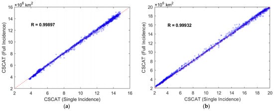
Figure 15.
Comparison of sea ice extent from CSCAT dual modes during 2019–2022: (a) Arctic region; (b) Antarctic region.
4.2. Validation
For verification, this study intercompares four daily sea ice extents derived from the scatterometer data using the similar Bayesian algorithms. They include the sea ice extent retrieved from the CSCAT full incidence mode [12], the CSCAT single incidence mode in this paper, OSCAT on ScatSat-1 [20], and HSCAT [21]. Among them, the data of the two rotating pencil beam scatterometers (OSCAT and HSCAT) are used to validate the CSCAT equivalent rotating pencil beam mode. HSCAT employs a rotating pencil beam antenna operating at 13.256 GHz, and the backscatters are collected in a HH inner beam and VV outer beam at incidence angles of 41° and 48°, respectively. Due to the different satellite orbits of HSCAT-B and HSCAT-C, HSCAT-C data have a large data gap in the polar regions [24]. Therefore, the HSCAT-B data are chosen for comparison. The HSCAT-B L2 swath grid dataset is provided by the European Organization for the Exploitation of Meteorological Satellites (EUMETSAT), with a resolution of 25 km [21]. OSCAT on SCATSAT-1 uses a 1 m parabolic dish antenna and a dual-feed system to generate two conically scanning pencil beams in the Ku-band (13.515 GHz). The inner and outer beams are arranged with horizontal and vertical polarization, with corresponding incidence angles of 48.9° and 57.6°, respectively. EUMETSAT also provides the SCATSAT-1 L2 swath grid dataset with a resolution of 25 km [20]. The timeline of these scatterometer data is visualized in Figure 16. Among them, OSCAT data from 2019 to 2020 and HSCAT-B data from 2022 are selected for comparison with CSCAT dual modes. Since the OSCAT and HSCAT-B data are at a 25 km swath grid, the polar stereographic projection is required to generate the sea ice extent maps [25].

Figure 16.
Timeline of the satellite scatterometer data used for comparison.
In addition, to further compare the sea ice extent retrieval performance of the CSCAT dual modes, the AMSR2 sea ice extent is taken as the main validation reference in this study. This is because the long-time sea ice product of passive radiometers provides an effective data source for comparison and analysis, and since 2012, the global sea ice observations have mainly relied on AMSR2 data. In this study, the AMSR2 sea ice extent is derived from the AMSR2 sea ice concentration data provided by the National Oceanic and Atmospheric Administration/National Snow and Ice Data Center (NOAA/NIDC) with a threshold of 15% [26].
Figure 17 shows the sea ice extent comparison among CSCAT dual modes, OSCAT, HSCAT-B, and AMSR2. As shown in the figure, the sea ice extent of CSCAT dual modes is closer to that of AMSR2, while OSCAT and HSCAT-B have significant differences from the other three, especially in the Arctic region. The reason for this phenomenon is that the sea ice extent of OSCAT and HSCAT-B are obtained from their L2 swath grid data, and in the data, wind retrieval is not performed when the land presence within each WVC exceeds a threshold (such as 0.02), and the ice probability information will not be written into the output L2 file. This leads to the significant differences in the sea ice detection at the sea land boundary, which explains the reason why OSCAT and HSCAT-B have a significantly smaller sea ice extent in the Arctic region. When the sea ice extent does not involve the sea land boundary zone, such as in the Arctic summer period, the sea ice extent of OSCAT and HSCAT-B has a certain consistency with that of CSCAT and AMSR2.
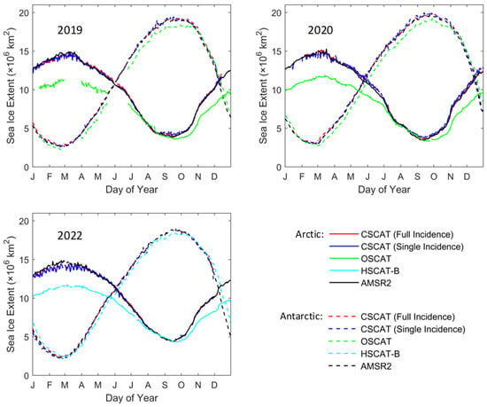
Figure 17.
Sea ice extent comparison among CSCAT dual modes, OSCAT, HSCAT-B, and AMSR2, for three years.
For quantitative comparison, we firstly use the AMSR2 data as a validation reference to calculate the root mean squared error (RMSE) of sea ice extent comparisons, viz., CSCAT full incidence mode versus AMSR2 and CSCAT single incidence mode versus AMSR2. Table 2 gives the RMSE of CSCAT dual modes versus AMSR2.

Table 2.
The RMSE of CSCAT dual modes versus AMSR2.
As shown in Table 2, in the Arctic region, the RMSE values of the CSCAT full incidence mode versus AMSR2 are approximately 0.22 (2019–2020) and 0.28 (2022) million km2 respectively, while the RMSE values of the CSCAT single incidence mode versus AMSR2 are all larger. In 2019, the RMSE difference between the two modes is about 0.01 million km2, and in 2020 it is about 0.9 million km2. This suggests that the sea ice extent obtained from the CSCAT full incidence mode is closer to that of AMSR2. In the Antarctic region, except for 2019, the RMSE of the CSCAT full incidence mode versus AMSR2 is also smaller than that of the CSCAT single incidence mode versus AMSR2. Then, we further analyze the monthly RMSE distribution of CSCAT dual modes compared with AMSR2 in the Antarctic region, and the results are shown in Figure 18. It can be seen that during January, February, and October to December in 2019–2020, the RMSE value corresponding to the CSCAT full incidence mode is higher than that of the CSCAT single incidence mode. Nevertheless, a significant difference happens in October to December 2019, which leads to a larger RMSE value in Table 2. To some extent, this reflects that the full incidence mode of CSCAT may be more sensitive to the freezing process of the open water.
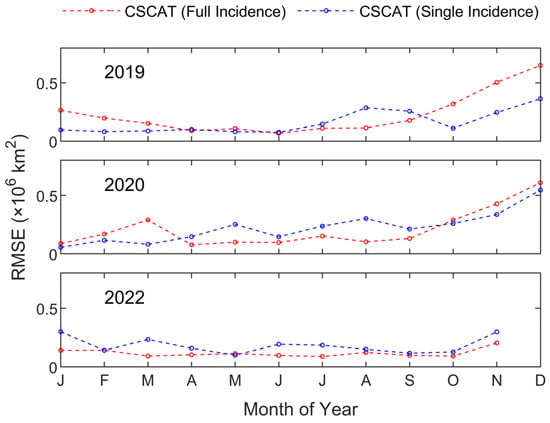
Figure 18.
Monthly RMSE distribution of CSCAT dual modes in the Antarctic region.
Secondly, we compare the sea ice extent of the CSCAT single incidence mode with the rotating pencil beam scatterometers, OSCAT and HSCAT-B. To address the limitations of OSCAT and HSCAT-B sea ice extent data, the OSCAT and HSCAT-B sea ice maps are taken as references. The sea ice extent of the CSCAT single incidence mode and AMSR2 are calculated when their sea ice map pixels are located on the grid points marked as ice on the reference sea ice map. The obtained results are shown in Figure 19. Note that there are certain differences in sea ice extent for the CSCAT single incidence mode, OSCAT, and HSCAT-B. The sea ice extent of the CSCAT single incidence mode is most consistent with that of AMSR2. In the Arctic region, the sea ice extent of OSCAT and HSCAT-B is overestimated compared to the CSCAT single incidence mode and AMSR2 from January to September. In the Antarctic region, the sea ice extent of OSCAT is overestimated from January to February and from October to December, while the sea ice extent of HSCAT-B is overestimated throughout the year. The reason for this phenomenon is that the measurement resolution of OSCAT and HSCAT-B is more than three times that of CSCAT (10 km), and the different resolutions can affect the accuracy of sea ice extent retrieval.
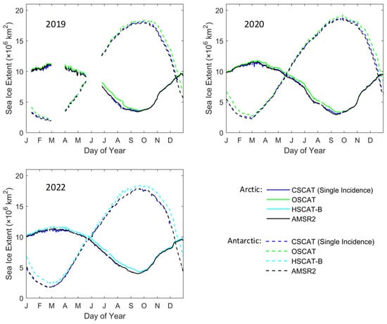
Figure 19.
Sea ice extent comparison for the different rotating pencil beam scatterometer data.
Furthermore, two metrics (RMSE and relative coefficient) are calculated corresponding to the results in Figure 19, and the metric values are presented in Table 3. It can be seen that compared to OSCAT and HSCAT-B, the RMSE of the CSCAT single incidence mode in the Arctic region is about 0.4 million km2, while in the Antarctic region, the RMSE of the CSCAT single incidence mode is about 0.6 million km2 compared to OSCAT, and about 0.8 million km2 compared to HSCAT-B. Furthermore, the RMSEs of AMSR2 versus OSCAT, HSCAT-B, and the CSCAT single incidence mode are calculated. The resulting RMSE of AMSR2 versus OSCAT and HSCAT-B is basically the same, with a value of about 0.35 km2 in the Arctic region. In the Antarctic region, the RMSE of AMSR2 versus HSCAT-B is relatively large, about 1.0 km2. In contrast to the two rotating pencil beam scatterometers, the RMSE of the AMSR2 versus the CSCAT single incidence mode is the smallest, at approximately 0.1 million km2 in the Arctic region and 0.2 million km2 in the Antarctic region. The comparison results of the correlation coefficients R are also presented in the table. It is found that the sea ice compared with OSCAT and HSCAT-B, and the sea ice extent of AMSR2, has the highest correlation coefficient with that of the CSCAT single incidence mode, indicating that the sea ice extent consistency between CSCAT and AMSR2 is the best.

Table 3.
The RMSE and relative coefficient R corresponding to the results in Figure 19.
4.3. Evaluation of the Dual-Mode Sea Ice Extent
In order to further quantitatively compare the sea ice extent retrieval performance of the CSCAT dual modes, two evaluation metrics are utilized, i.e., error-of-ice (EI) and ice edge location distance (LD) [27]. The definitions of the two metrics are as follows:
where and are the pixel numbers of overestimated and underestimated sea ice extent, respectively, is the sea ice extent of AMSR2, denotes the ice edge for the AMSR2 sea ice extent image, EO is the error of overestimation, , and EU refers to the error of underestimation, .
To calculate the metrics, the CSCAT dual-mode sea ice extent images are validated on the AMSR2 sea ice extent images. Figure 20 shows the spatial distribution of overestimated, underestimated, and overlapping sea ice pixels in the sea ice extent images of CSCAT dual modes compared with AMSR2. The overestimated, underestimated, and overlapping sea ice pixels in the images are denoted as red, light blue, and light gray, respectively. The sea ice boundary is represented by the black solid line, which is calculated using the AMSR2 sea ice concentration with a threshold of 15%. and are the sum of all overestimated (or red) and underestimated (or light blue) sea ice pixels. It is noted that there are certain differences in the overestimation/underestimation ice extent distribution of the two CSCAT modes in the Arctic and Antarctic regions. For the Arctic or Antarctic region, the overestimation of pixel count in the full incidence mode of CSCAT is greater than that in the single incidence mode of CSCAT, while the underestimation of pixel count in the full incidence mode of CSCAT is smaller than that in the single incidence mode of CSCAT. The total number of overestimation and underestimation pixels for both polar regions is less for the CSCAT full incidence mode, which indicates the sea ice extent derived from the CSCAT full incidence mode is closer to that of AMSR2.
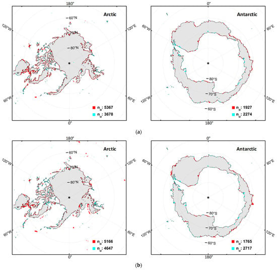
Figure 20.
Spatial distributions of the overestimated (red), underestimated (light blue), and overlapping (light gray) ice pixels in the sea ice extent images of CSCAT compared to AMSR2 on 10 June 2019: (a) CSCAT full incidence mode; (b) CSCAT single incidence mode. Non-ice pixels are set to white. The black lines represent the sea ice edges of AMSR2 at 15% sea ice concentration. and correspond to the sum of all red and light blue ice pixels.
Furthermore, the comparisons of EI, EO, and EU between the sea ice extent resulting from CSCAT dual modes for the three years (2019, 2020, 2022) are shown in Figure 21. In the Arctic region, the EI of the full incidence mode of CSCAT is relatively lower in June to November of each year, which corresponds to the period of late spring to middle autumn. Due to the almost identical EU of these two modes, the lower EI is mainly contributed by EO. This indicates that multiple incidence measurement data are more conducive to capturing the freeze–thaw process of sea ice. The EI between CSCAT dual modes and AMSR2 is around 18%, and the EI is lesser for the CSCAT full incidence mode. For the Antarctic region, the EI corresponding to the two modes of CSCAT is basically the same, while the EI for the full incidence mode of CSCAT is more stable. By comparing the EO and EI, it is not difficult to find that during the ice melting period (January to March each year), all incidence modes of CSCAT result in higher EO but lower EU. However, the single incidence mode of CSCAT results in opposite characteristics. In addition, the EI between CSCAT and AMSER is around 20% in the Antarctic summer period, and 5% in the other times.
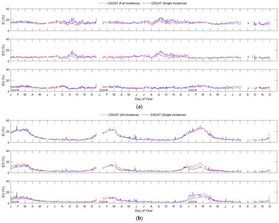
Figure 21.
Comparison of EI, EO, and EU between the sea ice extent resulting from the CSCAT dual mode for the three years (2019, 2020, 2022): (a) Arctic region; (b) Antarctic region.
Figure 22 also gives a comparison of LD between the sea ice extent resulting from CSCAT dual modes for both Arctic and Antarctic regions. As shown in this figure, in the Arctic region, the LD for the full incidence mode of CSCAT is smaller than that of the single incidence mode from June and November, which indicates the full incidence mode of CSCAT can obtain a closer ice edge with AMSR2. In the Antarctic region, the LD for the CSCAT dual modes is similar, but the LD of the single incidence mode fluctuates significantly. Overall, the CSCAT full incidence mode can obtain the ice edge closer to AMSR2, with the LD of approximately 12.5 km in the Arctic region and less than 10 km in the Antarctic region.
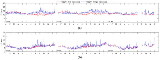
Figure 22.
Comparison of LD between the sea ice extent resulted from CSCAT dual modes for the three years (2019, 2020, 2022): (a) Arctic region; (b) Antarctic region.
5. Conclusions
This study proposes a dual-mode sea ice extent retrieval method for the rotating fan beam scatterometer to objectively evaluate the two rotating beam (pencil beam and fan beam) scatterometers on the basis of the same system and the synchronous spatiotemporal observations. The dual modes refer to the rotating fan beam mode (or full incidence mode) and the equivalent rotating pencil beam mode (single incidence mode). The rotating fan beam mode sea ice detection has been investigated in our previous studies, so the sea ice extent retrieval by the equivalent rotating pencil beam mode is emphasized in this study. The implementation of this mode includes data preprocessing and parameter settings of the Bayesian algorithm.
The performance of the CSCAT equivalent rotating pencil beam mode is analyzed by comparing it with the existing rotating pencil beam scatterometer (OSCAT on ScatSat-1 and HSCAT-B). The results indicate that, using the AMSR2 as a reference, the sea ice extent derived by the CSCAT single incidence mode has a good consistency with the reference in both polar regions, while OSCAT and HSCAT-B show higher estimates than the reference during the period January to September in the Arctic region. In the Antarctic region, the sea ice extent of HSCAT-B for the whole year of 2022 is overestimated, and the sea ice extent of OSCAT for January to February and October to December 2019–2020 is overestimated. The reason for this phenomenon is that their different measurement resolutions (that of CSCAT is about 10 km and that of OSCAT/HSCAT-B exceeds 30 km) may affect the accuracy of the sea ice extent retrieval. In summary, it is possible to retrieve the sea ice extent from the equivalent rotating pencil beam mode of the rotating fan beam scatterometer, and compared to OSCAT and HSCAT-B, the derived sea ice extent is closer to that of AMSR2.
In order to objectively evaluate the rotating pencil beam and the rotating fan beam scatterometers, the dual-mode sea ice extent obtained from CSCAT is compared. The results suggest that the majority of sea ice extents of the two modes of CSCAT have good consistency, and there are certain differences during the sea ice melting, especially in the Antarctic region. Compared to AMSR2, the sea ice extent of the CSCAT full incidence mode is closer to AMSR2 than that of the CSCAT single incidence mode. In the Arctic region, the RMSE values of the CSCAT full incidence mode versus AMSR2 are about 0.22 (2019–2020) and 0.28 (2022) million km2, while the RMSE values of the CSCAT single incidence mode versus AMSR2 are all larger. In the Antarctic region, except for 2019, the RMSE of the CSCAT full incidence mode versus AMSR2 is also smaller than that of the CSCAT single incidence mode versus AMSR2. In addition, the quantitative comparisons are made using the evaluation metrics of EI, EO, EU, and LD. The results indicate that in the Arctic region, the EI of the CSCAT full incidence mode is relatively lower than that of the single incidence mode. The lower EI is mainly contributed by the lower EO, indicating that multiple incidence measurement data are more conducive to capture the freeze–thaw process of sea ice. For the Antarctic region, the EI corresponding to the two modes of CSCAT are basically the same, with a value of 20% in summer and 5% at other times. However, the EI of the CSCAT full incidence mode is more stable. In the Arctic region, the LD of the CSCAT full incidence mode is about 12.5 km, which is smaller than the LD of the CSCAT single incidence mode. In the Antarctic region, the LD of the CSCAT dual modes is similar and less than 10 km, but the LD distribution of the single incidence mode shows significant fluctuations. Therefore, our results suggest that the rotating fan beam scatterometer shows better observation abilities for sea ice extent than the rotating pencil beam scatterometers.
Author Contributions
Conceptualization, L.L. and X.D.; methodology, L.L. and W.L.; software, L.L.; validation, L.L.; formal analysis, L.L.; investigation, L.L.; resources, S.L.; data curation, L.L.; writing—original draft preparation, L.L.; writing—review and editing, L.L. and W.L.; visualization, L.L.; supervision, X.D.; project administration, L.L.; funding acquisition, L.L. and S.L. All authors have read and agreed to the published version of the manuscript.
Funding
This research is funded by the National Natural Science Foundation of China (Grant No. 41806209) and Project 2023CFO017 supported by Key Laboratory of Space Ocean Remote Sensing and Application, MNR.
Data Availability Statement
The CSCAT scientific product used in the study is available at NSOAS website: https://osdds.nsoas.org.cn/home (accessed on 10 February 2024). The NSIDC AMSR2 sea ice concentration data are available at https://nsidc.org/data/ae_si12/versions/3 (accessed on 7 March 2024). The OSCAT data on ScatSat-1 are available at http://doi.org/10.15770/EUM_SAF_OSI_NRT_2009 (accessed on 1 April 2024). The HSCAT data on Hai Yang 2B are available at http://doi.org/10.15770/EUM_SAF_OSI_NRT_2000 (accessed on 5 April 2024).
Acknowledgments
We acknowledge the support of the NSOAS and CFOSAT team in providing the data, status, and mission information. The passive microwave datasets provided by NSIDC and the scatterometer datasets provided by EUMETSAT are much appreciated.
Conflicts of Interest
The authors declare no conflicts of interest.
References
- Singh, K. Studies of Polar Ice Using SCATSAT-1 Data. Ph.D. Thesis, National Institute of Technology Manipur, Imphal, India, 2024. [Google Scholar]
- Willis, M.D.; Lannuzel, D.; Else, B.; Angot, H.; Campbell, K.; Crabeck, O.; Delille, B.; Hayashida, H.; Lizotte, M.; Loose, B.; et al. Polar oceans and sea ice in a changing climate. Elem. Sci. Anthr. 2023, 11, 00056. [Google Scholar] [CrossRef]
- Singh, S.; Tiwari, R.K.; Sood, V.; Kaur, R.; Prashar, S. The Legacy of Scatterometers: Review of applications and perspective. IEEE Geosci. Remote Sens. Mag. 2022, 10, 39–65. [Google Scholar] [CrossRef]
- Sandven, S.; Spreen, G.; Heygster, G.; Girard-Ardhuin, F.; Farrell, S.L.; Dierking, W.; Allard, R.A. Sea Ice Remote Sensing—Recent Developments in Methods and Climate Data Sets. SGeo 2023, 44, 1653–1689. [Google Scholar] [CrossRef]
- Long, D.G. Polar Applications of Spaceborne Scatterometers. IEEE J. Sel. Top. Appl. Earth Obs. Remote Sens. 2017, 10, 2307–2320. [Google Scholar] [CrossRef]
- Amani, M.; Mohseni, F.; Layegh, N.F.; Nazari, M.E.; Fatolazadeh, F.; Salehi, A.; Ahmadi, S.A.; Ebrahimy, H.; Ghorbanian, A.; Jin, S.; et al. Remote Sensing Systems for Ocean: A Review (Part 2: Active Systems). IEEE J. Sel. Top. Appl. Earth Obs. Remote Sens. 2022, 15, 1421–1453. [Google Scholar] [CrossRef]
- Yun, R.; Dong, X.; Liu, J.; Lin, W.; Zhu, D.; Ma, J.; Lang, S.; Wang, Z. CFOSAT Rotating Fan-Beam Scatterometer Backscatter Measurement Processing. Earth Space Sci. 2021, 8, 1–18. [Google Scholar] [CrossRef]
- Shang, J.; Wang, Z.; Dou, F.; Yuan, M.; Yin, H.; Liu, L.; Wang, Y.; Hu, X.; Zhang, P. Preliminary Performance of the WindRAD Scatterometer Onboard the FY-3E Meteorological Satellite. IEEE Trans. Geosci. Remote Sens. 2024, 62, 1–13. [Google Scholar] [CrossRef]
- Zhai, X.; Wang, Z.; Zheng, Z.; Xu, R.; Dou, F.; Xu, N.; Zhang, X. Sea Ice Monitoring with CFOSAT Scatterometer Measurements Using Random Forest Classifier. Remote Sens. 2021, 13, 4686. [Google Scholar] [CrossRef]
- Li, Z.; Verhoef, A.; Stoffelen, A. Bayesian Sea Ice Detection Algorithm for CFOSAT. Remote Sens. 2022, 14, 3569. [Google Scholar] [CrossRef]
- Xu, C.; Wang, Z.; Zhai, X.; Lin, W.; He, Y. SVM-Based Sea Ice Extent Retrieval Using Multisource Scatterometer Measurements. Remote Sens. 2023, 15, 1630. [Google Scholar] [CrossRef]
- Liu, L.; Dong, X.; Lin, W.; Lang, S. Polar Sea Ice Detection Using a Rotating Fan Beam Scatterometer. Remote Sens. 2023, 15, 5063. [Google Scholar] [CrossRef]
- Liu, L.; Dong, X.; Yang, L.; Lin, W.; Lang, S. Sea Ice Extent Retrieval Using CSCAT 12. 5 km Sampling Data. Remote Sens. 2024, 16, 700. [Google Scholar] [CrossRef]
- Xu, R.; Zhao, C.; Zhai, X.; Chen, G. Arctic Sea Ice Type Classification by Combining CFOSCAT and AMSR-2 Data. Earth Space Sci. 2022, 9, 1–24. [Google Scholar] [CrossRef]
- Zhai, X.; Xu, R.; Wang, Z.; Zheng, Z.; Shou, Y.; Tian, S.; Tian, L.; Hu, X.; Xu, N. Classification of Arctic Sea Ice Type in CFOSAT Scatterometer Measurements Using a Random Forest Classifier. Remote Sens. 2023, 15, 1310. [Google Scholar] [CrossRef]
- Zhai, X.; Tian, S.; Ye, Y.; Cao, G.; Chen, L.; Xu, N.; Zheng, Z. First Results of Antarctic Sea Ice Classification Using Spaceborne Dual-Frequency Scatterometer FY-3E WindRAD. IEEE Geosci. Remote Sens. Lett. 2024, 21, 1–5. [Google Scholar] [CrossRef]
- Zhang, Z.; Yu, Y.; Shokr, M.; Li, X.; Ye, Y.; Cheng, X.; Chen, Z.; Hui, F. Intercomparison of Arctic Sea Ice Backscatter and Ice Type Classification Using Ku-Band and C-Band Scatterometers. IEEE Trans. Geosci. Remote Sens. 2022, 60, 1–18. [Google Scholar] [CrossRef]
- Rivas, M.B.; Stoffelen, A. New Bayesian Algorithm for Sea Ice Detection with QuikSCAT. IEEE Trans. Geosci. Remote Sens. 2011, 49, 1894–1901. [Google Scholar] [CrossRef]
- Rivas, M.B.; Otosaka, I.; Stoffelen, A.; Verhoef, A. A scatterometer record of sea ice extents and backscatter: 1992–2016. Cryosphere 2018, 12, 2941–2953. [Google Scholar] [CrossRef]
- OSCAT Winds at 25 km Swath Grid—ScatSat, EUMETSAT SAF on Ocean and Sea Ice. Available online: https://navigator.eumetsat.int/product/EO:EUM:DAT:0031 (accessed on 1 April 2024).
- HSCAT Winds at 25 km Swath Grid—Hai Yang 2B, EUMETSAT SAF on Ocean and Sea Ice. Available online: https://navigator.eumetsat.int/product/EO:EUM:DAT:0537 (accessed on 5 April 2024).
- Rivas, M.B.; Verspeek, J.; Verhoef, A.; Stoffelen, A. Bayesian Sea Ice Detection with the Advanced Scatterometer ASCAT. IEEE Trans. Geosci. Remote Sens. 2012, 50, 2649–2657. [Google Scholar] [CrossRef]
- Otosaka, I.; Rivas, M.B.; Stoffelen, A. Bayesian Sea Ice Detection with the ERS Scatterometer and Sea Ice Backscatter Model at C-Band. IEEE Trans. Geosci. Remote Sens. 2018, 56, 2248–2254. [Google Scholar] [CrossRef]
- Yang, S.; Zhang, L.; Lin, M.; Zou, J.; Mu, B.; Peng, H. Evaluation of Sea Surface Wind Products from Scatterometer Onboard the Chinese HY-2D Satellite. Remote Sens. 2023, 15, 852. [Google Scholar] [CrossRef]
- A Guide to NSIDC’s Polar Stereographic Projection, National Snow and Ice Data Center. Available online: https://nsidc.org/data/user-resources/help-center/guide-nsidcs-polar-stereographic-projection (accessed on 7 October 2023).
- AMSR-E/AMSR2 Unified L3 Daily 12.5 km Brightness Temperatures, Sea Ice Concentration, Motion & Snow Depth Polar Grids V001. Version 1. Available online: https://catalog.data.gov/dataset/amsr-e-amsr2-unified-l3-daily-12-5-km-brightness-temperatures-sea-ice-concentration-motion (accessed on 7 December 2023).
- Sun, Y.; Ye, Y.; Wang, S.; Liu, C.; Chen, Z.; Cheng, X. Evaluation of the AMSR2 Ice Extent at the Arctic Sea Ice Edge Using an SAR-Based Ice Extent Product. IEEE Trans. Geosci. Remote Sens. 2023, 61, 1–15. [Google Scholar] [CrossRef]
Disclaimer/Publisher’s Note: The statements, opinions and data contained in all publications are solely those of the individual author(s) and contributor(s) and not of MDPI and/or the editor(s). MDPI and/or the editor(s) disclaim responsibility for any injury to people or property resulting from any ideas, methods, instructions or products referred to in the content. |
© 2024 by the authors. Licensee MDPI, Basel, Switzerland. This article is an open access article distributed under the terms and conditions of the Creative Commons Attribution (CC BY) license (https://creativecommons.org/licenses/by/4.0/).